Week 5 Battery characteristics using drive cycle
AIM:
To model a generic battery charge and discharge using UDDS data
Procedure:
# UDDS drive cycle to be created and imported to the signal builder
# Then a battery model to be created with the UDDS data file
What is UDDS?
UDDS stands for Urban Dynamometer Driving Schedule and refers to a United state environment protection agency mandated dynamometer test on fuel economy that represents city driving conditions that are used for light-duty vehicle testing.
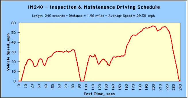
The above picture shows one of the UDDS drive cycle data from the graph. The cycle consists of its length, distance, average speed. The cycle shown is used for inspection & maintenance driving schedule.
Importing steps procedure:
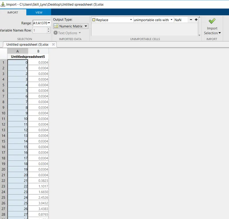
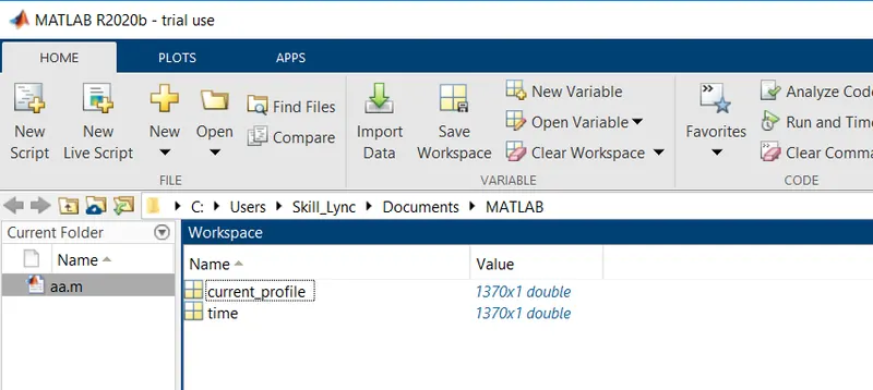
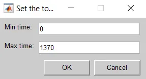
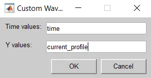
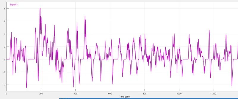
The UDDS data cycle is imported in the signal builder block. The below image shows the current profile VS time graph of the given data
SIMULINK MODEL:
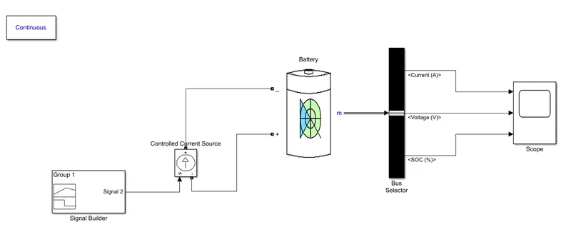
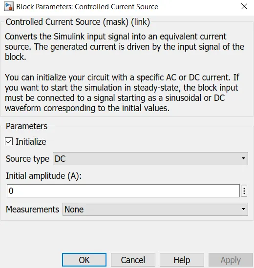
The controlled current source block is used for converting a numeric data signal into a current that feeds into the battery. Where in controlled current source type of source is changed into DC source
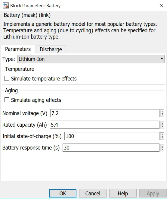
A generic battery block is used where lithium-ion is selected for the type of battery. By using lithium-ion cell datasheet the parameters of the battery is changed like the nominal voltage, rated capacity
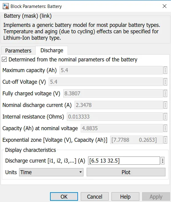
In the discharge tab, the cut-off voltage, nominal voltage, internal resistance, capacity are changed according to the battery datasheet
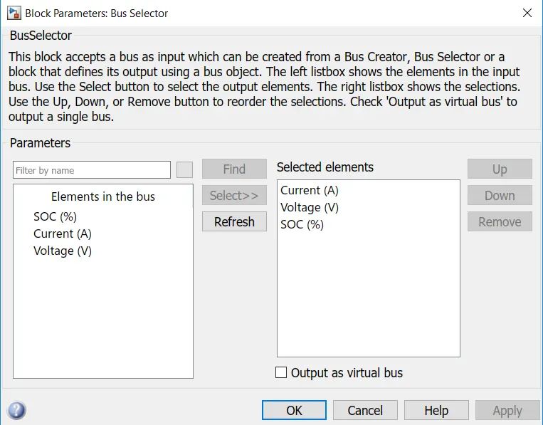
The bus selector block is used for creating a number of outputs defines from the single input. Here when the battery is connected to the bus selector the three outputs like the current, voltage, SOC is created to view the result performed by the drive cycle using the lithium-ion cell.
Result:
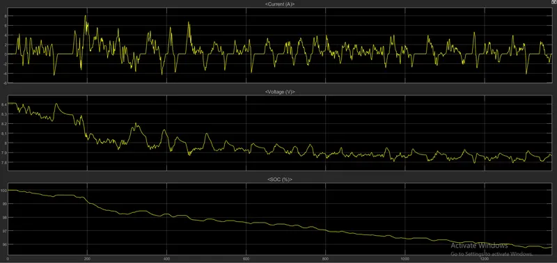
# From the above generic battery model charge-discharge using UDDS data.
# It can be observed that after a complete drive cycle the battery is discharged from a 100% charge state to around 94.5% charge state.
# Also, it can be observed that when the current profile goes in below zero value i.e negative current(-) actually used to increase the SOC level of battery during the period of deceleration or braking of the drive cycle. Thus battery gets charge during that moment.
# Here Current value varies between -4A to +8A.
#And Voltage vary between 5V to 3V.
Model Working:
Signal Builder
The Signal Builder block allows you to create interchangeable groups of piecewise linear signal sources and use them in a model. You can quickly switch the signal groups into and out of a model to facilitate testing. In the Signal Builder window, create signals and define the output waveforms.
Controlled Current Source
# The Controlled Current Source block converts the Simulink input signal into an equivalent current source. The generated current is driven by the input signal of the block. The positive current direction is as shown by the arrow in the block icon.
# You can initialize the Controlled Current Source block with a specific AC or DC current. If we want to start the simulation in steady-state, the block input must be connected to a signal starting as a sinusoidal or DC waveform corresponding to the initial values.
# Double click controlled current source and from the drop-down menu of measurement select current. The signal output will connect with a scope by adding the current signal to it. (+) the terminal will connect with the battery (-) terminal.
Battery
The Battery block implements a generic dynamic model that represents the most popular types of rechargeable batteries.
BUS Selector
# The Bus Selector block outputs the signals you select from the input bus. The block can output the selected elements separately or in a new virtual bus.
# So from the input of battery select SOC%, Current & Voltage to output scope.
PowerGUI
# The powergui block allows you to choose one of these methods to solve your circuit
# Continuous, which uses a variable-step solver from Simulink
# Discretization of the electrical system for a solution at fixed time steps Continuous or discrete phasor solution
# The powergui block also opens tools for steady-state and simulation results analysis and for advanced parameter design.
# You need the powergui block to simulate any Simulink model containing Simscape Electrical Specialized Power Systems blocks.
# It stores the equivalent Simulink circuit that represents the state-space equations of the model.
Scope
Display signals generated during simulation.