Week 5.3 - Forced convection Analysis
Forced Convection Analysis
Aim
The objective of the project is to convert CAD shapes into Icepak primitive shapes in Spaceclaim & modify the components in Icepak & define the correct physics.
Objective
The total number of bodies in the CAD model is calculated. Depending on the functionality of individual bodies or groups of bodies the objects are segregated of the bodies. The properties of the bodies for analysis for the thermal and flow analysis is provided.
Theory
Types of bodies
Focus bodies - The bodies which will emit some heat or obstruct the flow of the system.
Necessary bodies - The bodies which will have some effects on the focus bodies.
Peripheral bodies - These bodies may or may not affect the focus bodies.
Dispensable bodies - The small bodies on the assembly which has no effect on the physics of the system, these bodies are completely neglected.
Forced convection:
In natural convection, and fluid motion is caused by natural means such as the buoyancy effect, i.e. the rise of warmer fluid and fall the cooler fluid. In forced convection, the fluid is forced to flow over a surface or in a tube by external means such as a pump or fan. Forced convection is used where heat transfer is more and quick cooling is required. Forced convection is often encountered by engineers designing or analyzing heat exchangers, pipe flow, and flow over a plate at a different temperature than the stream. The heat transfer coefficient of forced convection is high compared to natural convection.
Geometry
The workbench is used for the geometry simplification and the Space claim is used to convert CAD objects into Icepak objects and open the dme.stp file.
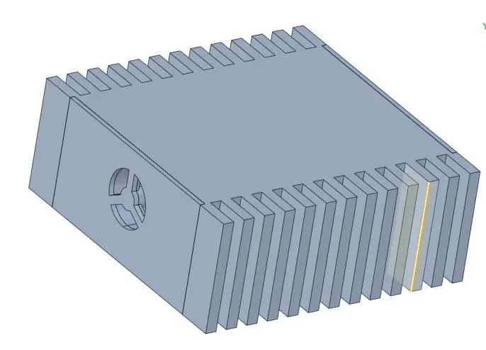
The enclosure, the grille and the fan closure are hidden to view the interior objects of the model.
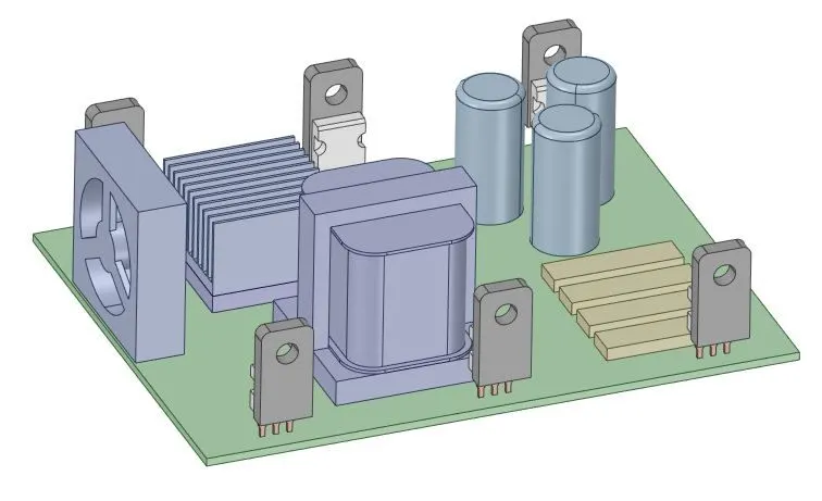
Tools used
Split body -Before the split
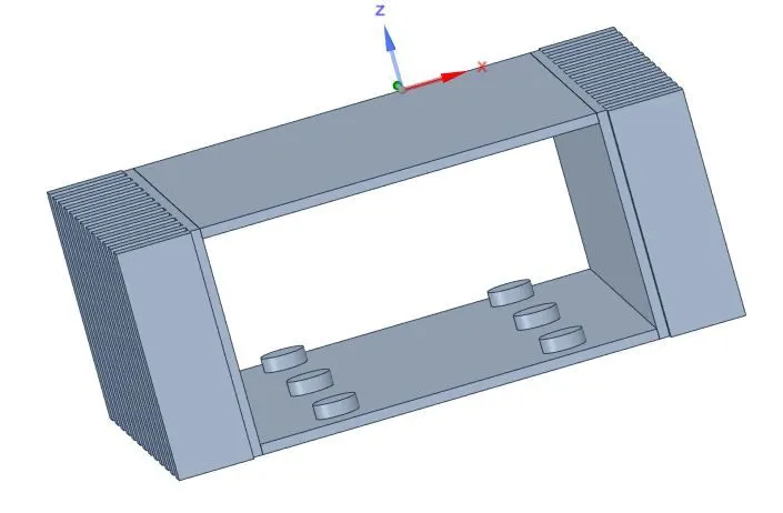
After the split
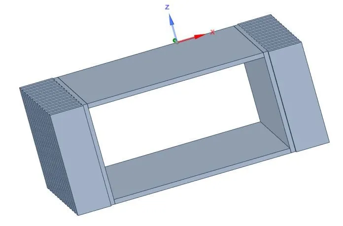
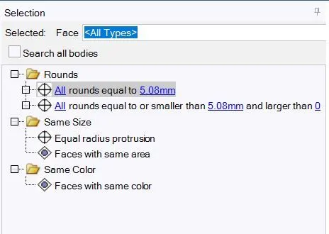
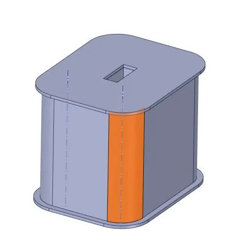
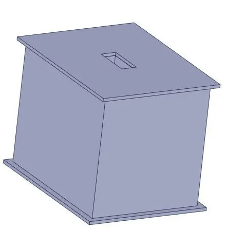
Delete Curvature
Combine
Before Combine
After Combine
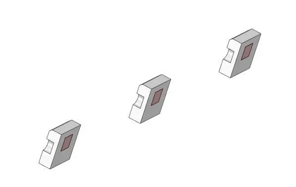
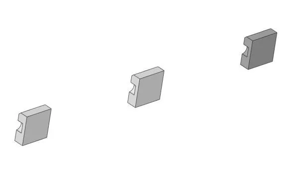
Fill gaps.
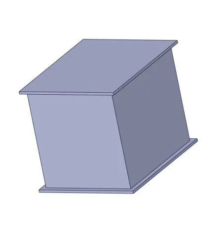
Fan
Fan - This command is used to convert the Fan CAD model to the Icepak model.
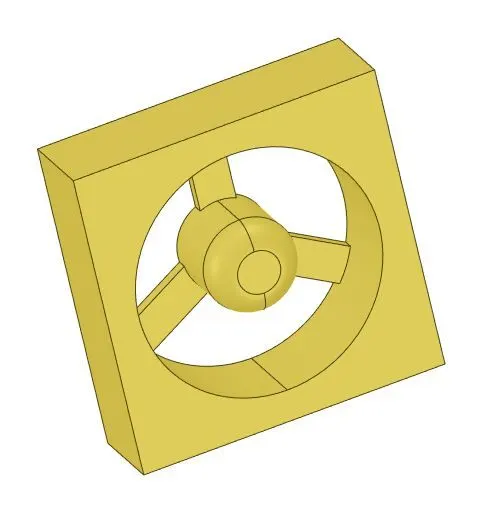
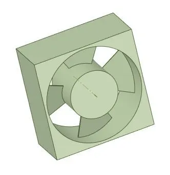
Grille
Grille - This command is used to create a grille on the inlet side of the model. The Face of the grille is selected & the grille surface is created for the cooling of the PCB board.
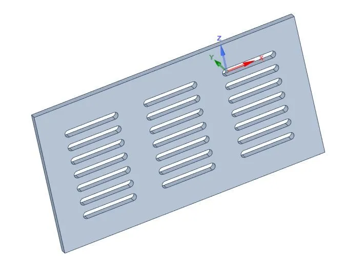
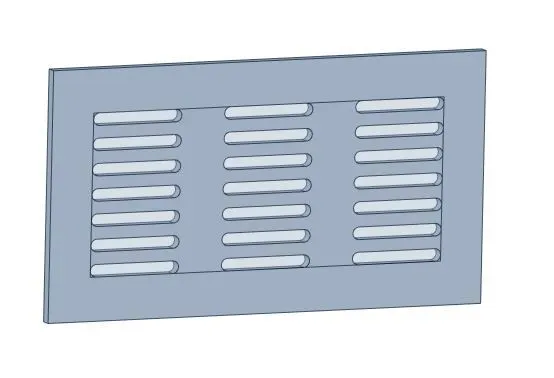
so the other small components are deleted.
The components may overlap during the model conversion but these problems must be solved using the split command. The sketch tool is used to create a line & the pull command is used to create a surface that acts as the plane of separation between the bodies.
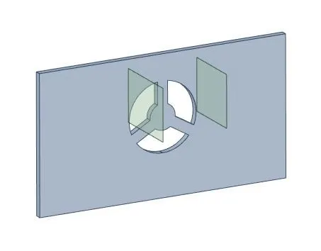
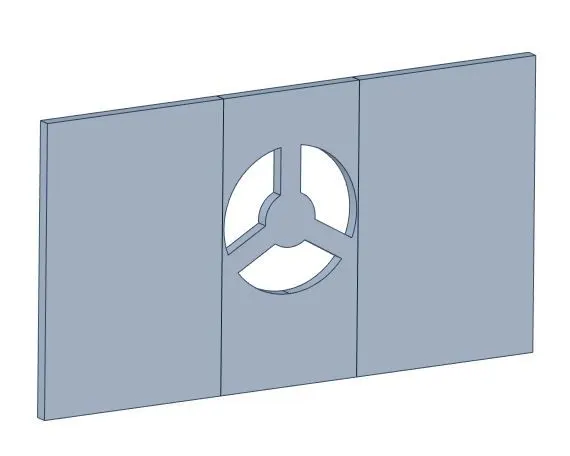
The final model of the PCB is in which the connectors and dispensable bodies are deleted.
The next step is to convert the CAD model into icepck objects.
Identify objects - This option converts automatically CAD objects into Icepak objects and other objects are converted using Icepak Simplify option.
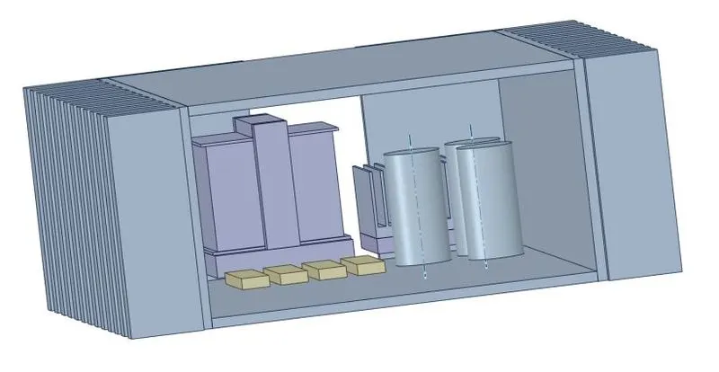
Level 0 Conversion
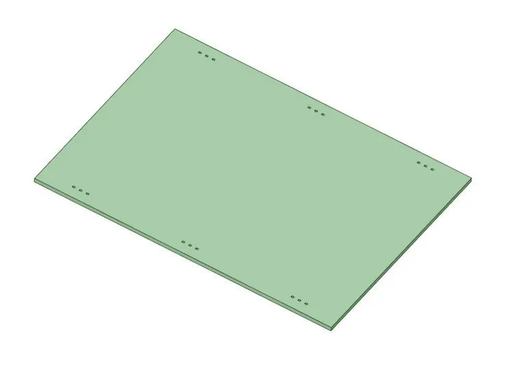
Level 1 Conversion
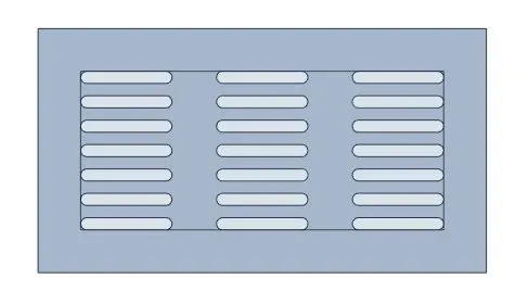
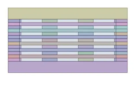
Level 3 Conversion

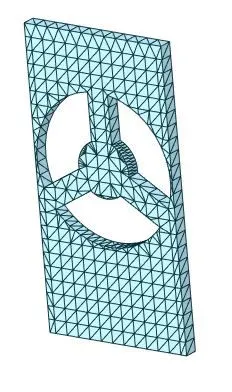
By this method, all the objects are converted into Icepak objects.
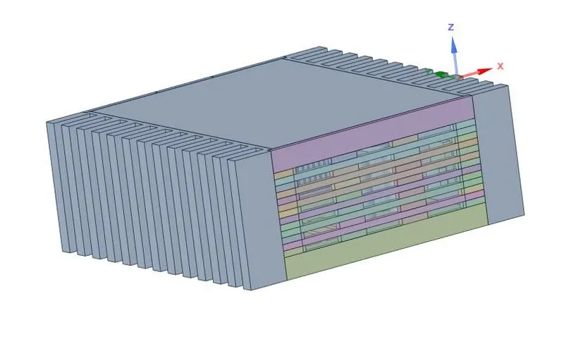
Icepak
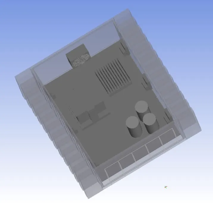
The model is further simplified by removing the fan opening, grille objects and the 3D fan is replaced by a 2D fan.
Fan parameters
Fan type - Internal.
Flow direction - Normal - positive.
Fan flow - flow type - Non-linear.
From the non-linear curve use load option is used to import the fan curve.
The Rpm value of the fan under the swirl is provided as 4000.
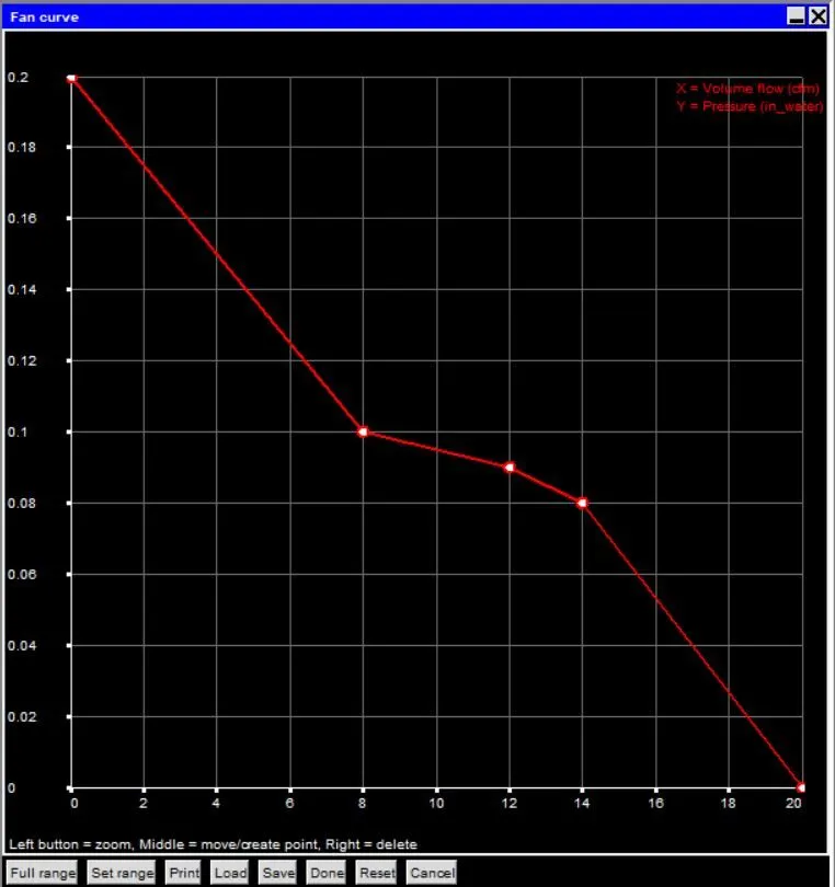
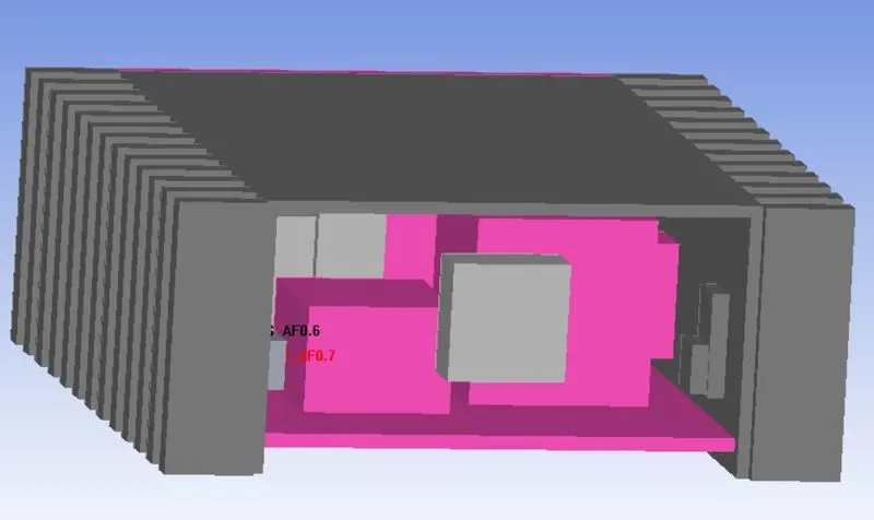
A total of 15 assemblies are created for the model.
The enclosure is divided into separate assemblies for the model depending on the meshing technique and slack is set to zero since the enclosure are attached the slack causes overlap of assembling.
The 6 assemble are created for the Mosfet model.
Assemble -1
i) Slack setting
Min X - 1 mm.
Max X - 0.
Min Y - 1 mm.
Max Y - 1 mm.
Min Z - 1 mm.
Max Z - 1 mm.
ii) Mesh type
Max element size X - 1.5 mm.
Max element size Y - 3 mm.
Max element size Z - 3 mm.
Min Gap X - 0.1 mm.
Min Gap Y - 0.15 mm.
Min Gap Z - 0.15 mm.
Assemble -2
i) Slack setting
Min X - 0.
Max X - 1 mm.
Min Y - 1 mm.
Max Y - 1 mm.
Min Z - 0.
Max Z - 1 mm.
ii) Mesh type
Max element size X - 0.6 mm.
Max element size Y - 0.6 mm.
Max element size Z - 2 mm.
Min Gap X - 0.06 mm.
Min Gap Y - 0.06 mm.
Min Gap Z - 0.2 mm.
Fan Assemble
i) Slack setting
Min X - 1 mm.
Max X - 1 mm.
Min Y - 1 mm.
Max Y - 0.
Min Z - 1 mm.
Max Z - 1 mm.
ii) Mesh type
Max element size X - 1 mm.
Max element size Y - 1 mm.
Max element size Z - 1 mm.
Min Gap X - 0.1 mm.
Min Gap Y - 0.1 mm.
Min Gap Z - 0.1 mm.
Assemble - 4
i) Slack setting
Min X - 1 mm.
Max X - 1 mm.
Min Y - 1 mm.
Max Y - 1 mm.
Min Z - 0.
Max Z - 1 mm.
ii) Mesh type
Max element size X - 3 mm.
Max element size Y - 3 mm.
Max element size Z - 3 mm.
Min Gap X - 0.75 mm.
Min Gap Y - 0.3175 mm.
Min Gap Z - 0.0635 mm.
Assemble -5
i) Slack setting
Min X - 1 mm.
Max X - 1 mm.
Min Y - 1 mm.
Max Y - 1 mm.
Min Z - 0.
Max Z - 1 mm.
ii) Mesh type
Max element size X - 2.5 mm.
Max element size Y - 2 mm.
Max element size Z - 2.5 mm.
Min Gap X - 0.15 mm.
Min Gap Y - 1 mm.
Min Gap Z - 0.35 mm.
Assemble -5
i) Slack setting
Min X - 0.5 mm.
Max X - 0.5 mm.
Min Y - 1 mm.
Max Y - 1 mm.
Min Z - 0.
Max Z - 1 mm.
ii) Mesh type
Max element size X - 8 mm.
Max element size Y - 8 mm.
Max element size Z - 1 mm.
Min Gap X - 2 mm.
Min Gap Y - 2 mm.
Min Gap Z - 0.15875 mm.
Final Model
Macros - Productivity - Validation - Automatic case check tool - This option checks for the model on various criteria.
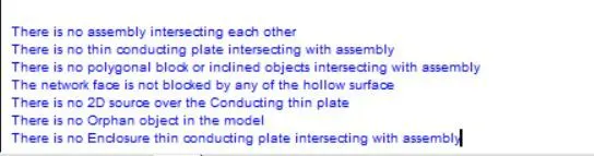
The CAD model is successfully converted into an Icepak object & the different errors in the model are correct.
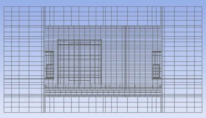
Mesh Control
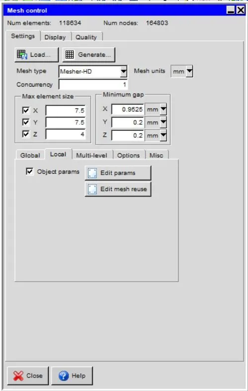
Y Cut plane
Setup
The Mosfet and the Coil are the two heat generating sources in the model & the Heat generated value is provided as input. Total power generated - 2W for all the Mosfet & the coil also generate 2 W of heat.
Solver
The three-dimensional steady-state Navier stokes equations for the model are solved within the computational domain.
- Variables solved - flow and temperature.
- Radiation - Off.
- Flow regime - Turbulent - The zero equations are solved for the turbulent model.
Natural convection is not considered for this model & also gravity vectors are not considered.
The defaults value of the parameters is set to default.
Transient Setup
- Time variation - Steady
Solution Initialization
X velocity - 0.
Y velocity - 0.
Z velocity -0.
Temperature - ambient.
Basic settings
No of iterations - 100.
Convergence criteria
Flow - 0.001.
Energy - 1e-7.
Joule heating - 1e-7.
Parallel Settings
Configuration - parallel.
Parallel options - 2 processors.
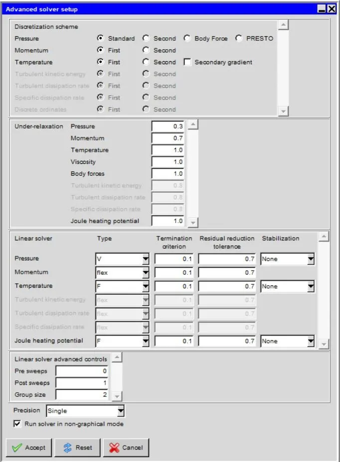
Advance Solver Setup
Results
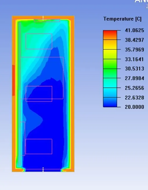
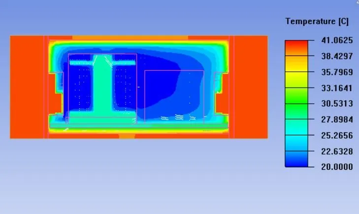
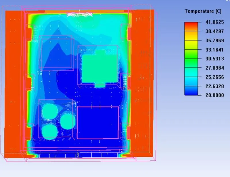
The maximum temperature is around 41.06 deg C & the min temp is at the ambient temp. The heat conduction near the MOSFET is high so the temp at the fins is also around 40 deg C and heat transfer through convection is low.
Velocity plot
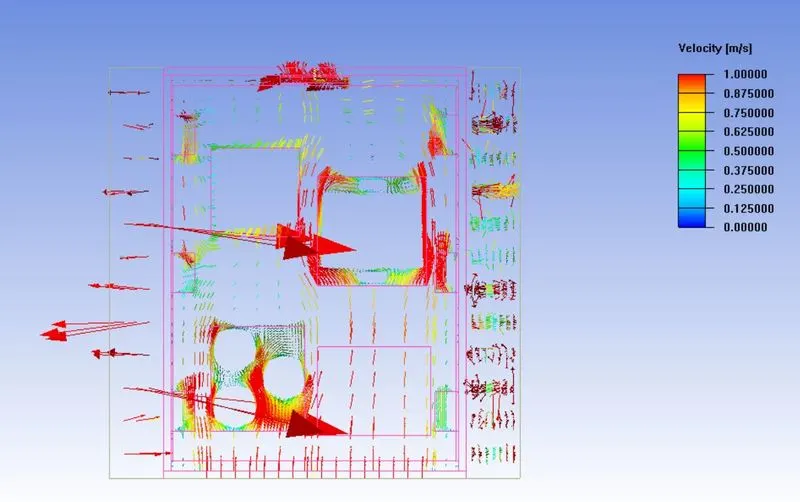
The velocity is maximum around the fan & the heat source which causes heat transfer.
Conclusion
- The geometric cleaning is performed to capture the thermal cooling effect significantly.
- The assembly meshing is performed to reduce the mesh bleeding effect and mesh counts.
- The temperature contour shows appropriate results for cooling the internal components of the enclosure.