Week - 5 - 2D meshing for Plastic components
Aim:
To create a Mid-Surface and mesh with the given quality criteria and to make sure the element given is free from geometrical errors.
Methodology:
The methodology for the given element is as follows:
- Perform a Geometrical Check ( if Errors present fix them)
- Extraction of Mid surface
- Assigning Thickness to Mid surface.
- Giving the Quality Criteria.
- Creating a mesh
- Adding thickness to the meshed element.
Introduction
- A bottle cap or bottle top seals the top opening of a bottle.
- A cap is typically colorfully decorated with the logo of the brand of beverage.
- Plastic caps are used for plastic bottles, while metal with plastic backing is used for glass; the metal is usually steel.
- Plastic caps may have a pour spout. Flip-Top caps like Flapper closures provide controlled dispensing of dry products.
- Caps for plastic bottles are often made of a different type of plastic from the bottle.
- The easiest and most common method to produce the Bottle cap is Injection Moulding.
- Injection Moulding is the process for producing parts by injecting molten material into a mold, or mold. Injection moulding can be performed with a host of materials mainly including metals (known as die-casting), glasses, elastomers, confections, and most commonly thermoplastic and thermosetting polymers.
Procedure:
Opening the File:
The file is downloaded initially. To open the file, follow the steps.
Click on File--->Open (Ctrl+O)--->Browse to the location of downloaded file--->Click to select--->Ok
Checking for any errors:
- This process is used to check any errors present in the model.
- For Topology, Click Topo--->Select Model--->Middle-Click on Mouse.
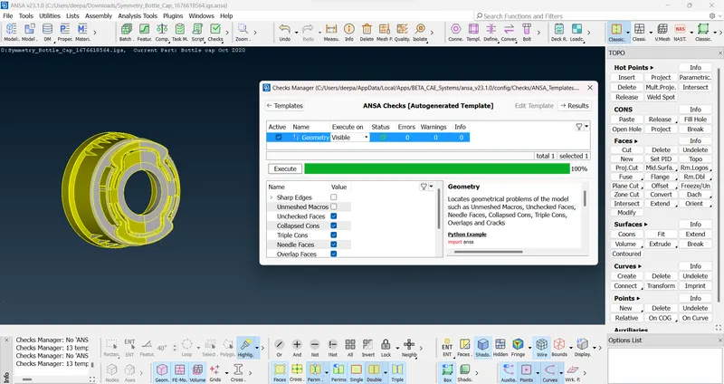
- In order to check the Topology follow the process as Tools--->Checks--->Geometry--->Execute.
- These errors can be fixed either by working on with them individually or once Right-clicked on the mouse an additional list pops-up.
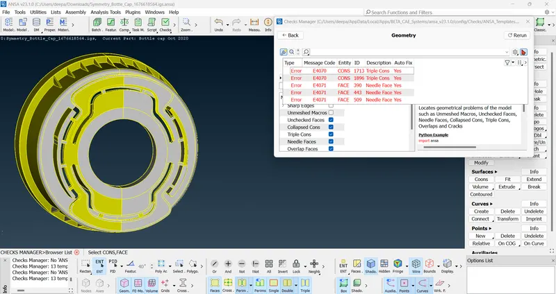
5. Fix option will be present in that pop-up when it is clicked the errors which can be fixed are executed and it might contain only a few errors which should be fixed manually and if no errors are present then it will show the green bar stating executed.
Creating the Midsurface:
- Before extracting the mid-surface for the component, the thickness of each of the surfaces needs to be known. The thickness of the surfaces can be measured using the MEASURE command, which is under the UTILITIES tab.
- By selecting the CONS/Curves option, the distance between two CONS or Curves can be measured and the thickness value is stored. Similarly, the thickness values are measured at various places in the CAD model.
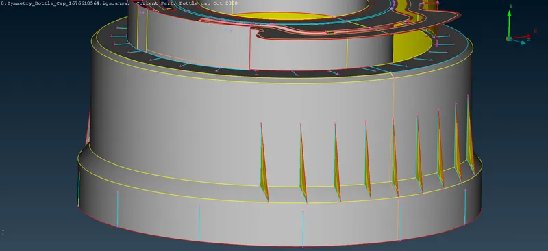
- In places where there are varying thicknesses, the CURVES--->MIDDLE command is used to generate a middle curve between the two curves. This procedure is followed at the top and bottom. Then a new surface is created connecting the two middle curves. This surface serves as the mid-surface.
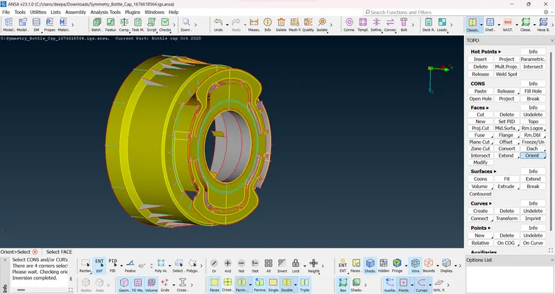
- Upon selecting the curves and accepting the command, a middle curve is generated. Similarly, this process is done in the bottom surface also.
- The curve in the bottom surface is generated and can be seen only when the SHADOW mode is turned off. Then, the mid-surface is created by creating a new surface between the two curves. The new surface is created using the FACES---> NEW command.
- Upon accepting the command, a new surface is created, which is the mid-surface for that particular part. The mid-surface is generally in red colour as they consist of single cons. The same process can be followed to extract mid-surface for all similar features.
- The mid-surface for some surfaces can be done using the FACES--->MIDDLE command. This command generally creates a middle face for the selected faces.
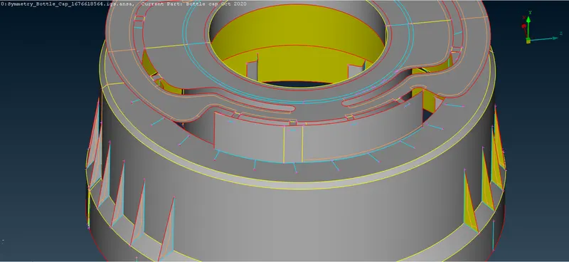
- Upon selecting the faces, the confirmation window will pop up. After accepting, the middle face is created between the two selected faces. This will serve as the mid-surface for that part.
- The same method is followed for all the similar features.
- In this command, we have a disadvantage. Only one hot point can be projected at a time. By using HOT POINTS-->MULTI PROJECT multiple hot points can be projected at the same time.
- NOTE: MULTI PROJECT can only be used to project multiple hot points to the same surface. Projecting to multiple surfaces is not possible.
- Now, to measure the thickness of the surfaces, the distance between the hotpoints is measured. This value is the thickness between the surface.
Create a PID for Mid Surface:
- PID for mid surfaces is created so that the element can be retrieved easily.
- To create the PID for mid surface, the above method (Checking the PID) can be used to create a new PID.
- The Mid surface part is selected as each part has its thickness and to differentiate each of those parts different PIDs are taken.
ASSIGN THICKNESS & QUALITY CRITERIA
- The thickness are assigned to the mid-surfaces according to the thickness in the parent surface.
- After the thickness is assigned, the quality criteria and the mesh parameters need to be assigned. The given quality criteria is as below.
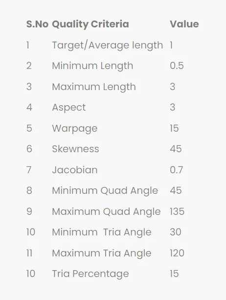
- The quality criteria is opened by either clicking F11 on the keyboard or by clicking Utilities--->Quality Criteria.
- After Giving Quality Parameters in the Shell icon, click on apply and then click Presentation Parameters and select element percentage and Detail on Demand effect to all details.
- The Meshing parameters are also added from Utilities--->Meshing Parameters.
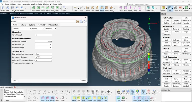
Creating the Mesh Flow:
- To create a mesh for any model, in modules select mesh.
- Click on the classic mesh deck from the top-right of the screen.
- Once the mesh module buttons are opened and seen.
- Firstly when the mid surface is opened in mesh mode, click Length in the procedure is as follows Length--->Perimeters, Macros. Select the entire model and confirm it, once it is done a dialog box appears stating the length as 1 in both perimeters and macros simultaneously.
- In mesh generation, Select Best and select the element to mesh and confirm it.
- The Mesh might not be as perfect as it should be and contains many Off elements (Which doesn’t meet the Quality Criteria)
- To remove the off elements or to reduce them Reconstruct option is used.
- It can be seen in Shell Mesh--->Reconstruct.
- Once the Off elements are fixed or reduced the mesh should be made smoother. To make the mesh Smooth option is used.
- It can be seen in Shell Mesh--->Smooth.
- If the Off elements are still present then it should be eliminated by using manual methods.
-
To manual deal with trias, the following tools are used-
- Grid>Paste, to paste the nodes and move tria backward.
- Elements>Split, to split an element and move tria forward.
- Elements>Swap, to move the tria left or right.
- Elements>Join, to join two trias to make a quad.
After modifying the mesh, Shell Mesh>Smooth tool is used to smoothen the flow of mesh. Any elements failing for quality criteria are also fixed by either re-meshing or smoothing the elements again.
- Make sure that there are no opposite tria’s and also rotating quads should be eliminated.
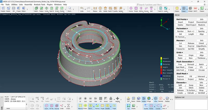
Result:
Mid-surfacing and Mesh generation has been achieved with Quads at 98.61%, Trias at 1.39% and Off at 1.18% of a Bottle Cap along with best possible mesh and thickness.
Learning Outcomes:
There are many methods to extract mid surface manually. Each method has its own merits and demerits. We should select that method which gives best result for given geometry.
Auto mid method of mid surface extraction doesn’t give accurate results but it can be used as a reference for manual mid surface extraction.
Manual mid surface extraction method should be preferred over auto mid generation for more accuracy.