Bending of Wire Using Ansys Workbench
OBJECTIVE
- To assign the structural steel material to the wheel and the lever, and to the wire, the material had to assign according to the case.
- To assign the frictional contacts.
- To mesh the model.
- To apply the boundary condition.
- To collect the results and interpret.
PROCEDURE
The simulation seems to be static non-linear, therefore, it had to solve using the Static Structural module of Ansys. The wheel, the lever, and the wire model are shown in the figure below. Next, the material had to define before proceeding further. Using Engineering data, all the required materials viz. structural steel, copper alloy (non-linear), aluminum alloy (non-linear), and magnesium alloy (non-linear) were imported.
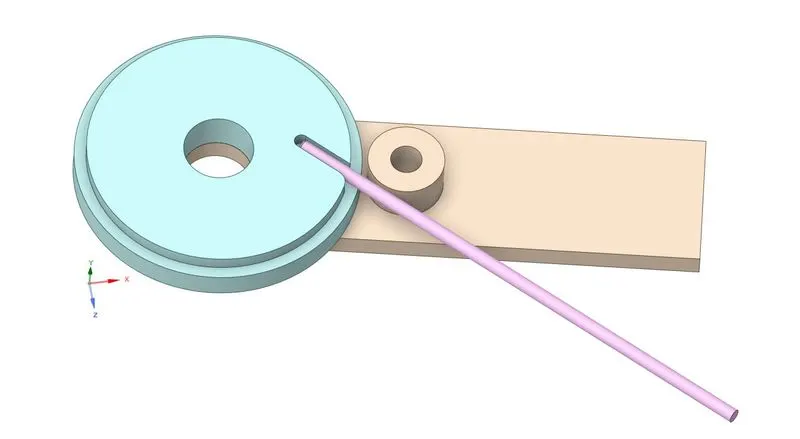
Figure 1: Wheel, lever, and wire model in Ansys GUI.
The Mesh section of the Static Structural module was opened. In that, the material of the wheel and the lever parts was set to structural steel, and the material of the wire was set to copper alloy.
Further, the Ansys already detected the contact regions, and therefore default bonded contact was created. The automatically created contact cards were kept as it is but made a slight modification in contacting faces. The behavior of contact was changed from bonded to frictional with a coefficient of friction of 0.2.
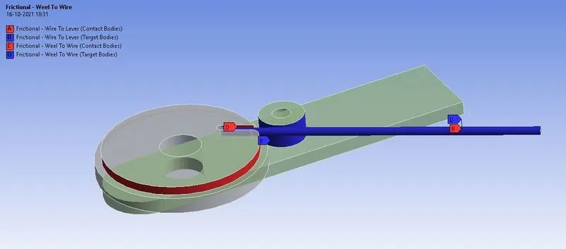
Figure 2: Frictional contact set between the contacting faces.
After contact, a revolute joint was created for the lever as shown in the figure below.
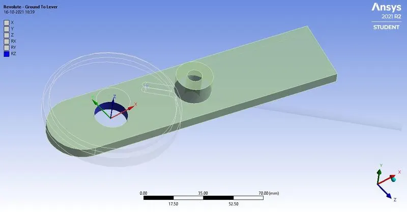
Figure 3: Revolute joint created for the lever.
Then mesh was created for the model with 0.8 mm element size for the wire, at its contact with the lever. The analysis was solved in 8 steps. In boundary conditions, the wheel was fixed, and the rotation was applied to the wheel as shown in the figure.
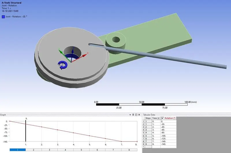
Figure 4: Displacement applied to the plate.
In the solution, the results for equivalent stress, and the equivalent strain were requested for wire. The figures below show the mode of deformation in the wire, using equivalent stress and equivalent strain contours. The results of each case are shown in the figures below.
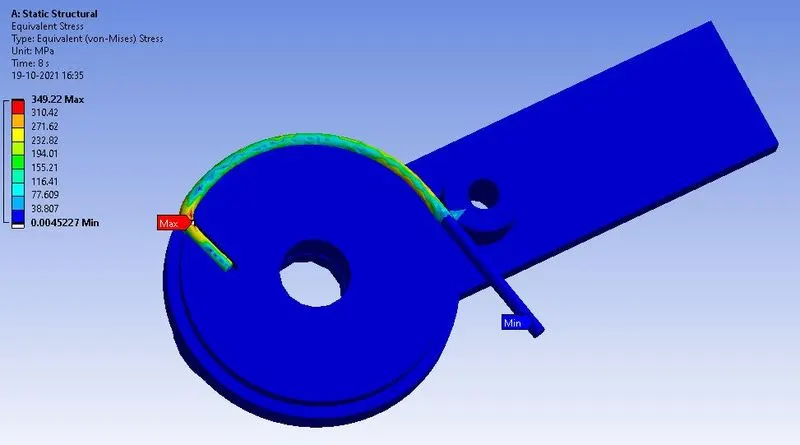
Figure 5: Equivalent stress contour of the model, when the material of the wire was copper alloy.
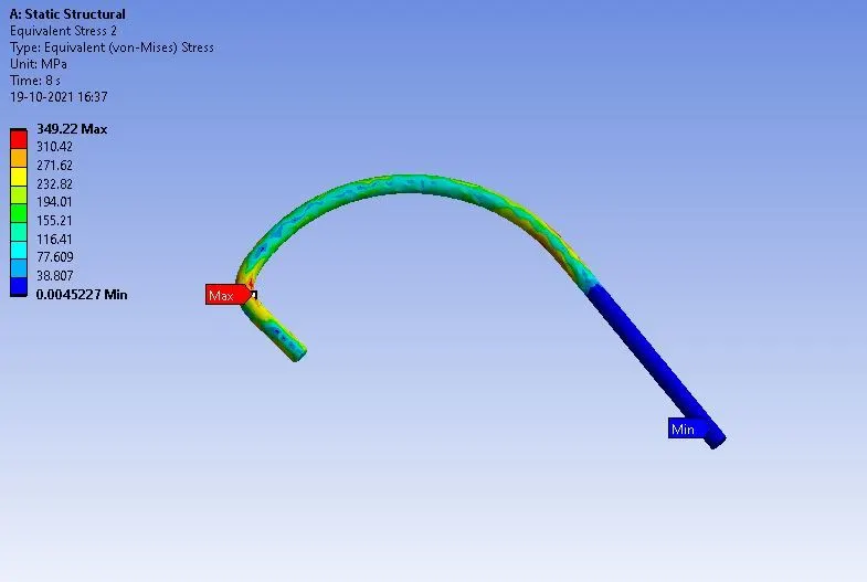
Figure 6: Equivalent stress in copper wire alone.
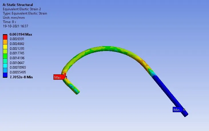
Figure 6: Equivalent stress in copper wire alone.
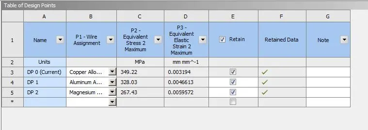
Figure 7: Equivalent maximum stress and strain in the wire, when its material was copper alloy, aluminum alloy, and magnesium alloy respectively.
CONCLUSION
In this work, wire bending simulation was performed to study the procedure of simulating the wire bending process. It was solved using three different materials of the wire. After solving it was found that in case 3 i.e. when the material of the wire was magnesium alloy, the maximum stress developed was least, equal to 267.43 MPa. This shows its inability to resist the deformation, and ability of formability. On the other hand, copper alloy is stiffer to deform, therefore, the stress-induced in it is equal to 349.22 MPa, more than aluminum alloy, and magnesium alloy.