Wire Bending Analysis
AIM:
- To perform static structural analysis of wire bending model using different materials and compare the results.
OBJECTIVES OF THE PROJECT:
- To add copper alloy NL, aluminium alloy NL and magnesium alloy NL material to the engineering data.
- To insert the contacts for the wheel, lever and the wire.
- To fix the wheel and define rotation for the lever.
- To fix the wire for movement from the wheel.
- To mesh the wheel, lever and the wire.
- To define the no of simulation steps and the analysis controls.
- To evaluate the stress and deformation in the work piece.
PROCEDURE:
- Case 1:
- OPEN WORKBENCH21 > NEW PROJECT > STATIC STRUCTURAL.
- This will start a new static structural project.
- Rename the project as copper NL.
- Go to ENGINEERING DATA > EDIT > GENERAL MATERIALS NL > COPPER ALLOY NL, ALUMINIUM ALLOY NL and MAGNESIUM ALLOY NL > ADD.
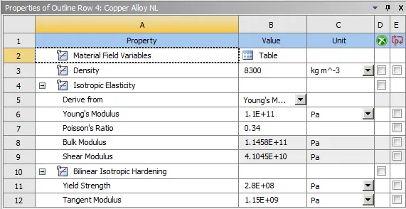
- This will add the copper alloy NL, aluminium alloy NL and magnesium alloy NL to the material data.
- Then double click on Geometry. This will open the Spaceclaim.
- In Space claim check the model for any dents or irregularities.
- The geometry looks good, exit the Spaceclaim.
- Then double click on Model. This will open Mechanical module.
- Now, rename the geometry as wheel, lever and wire.
- Then assign copper alloy NL to work piece.
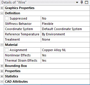
- Then go to CONTACTS > FLIP > RENAME BASED ON DEFINITION.
- Define the contact faces correctly for both the contacts.
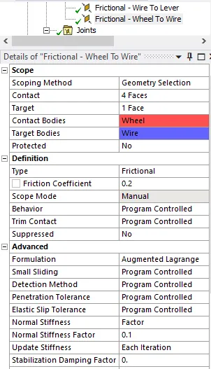
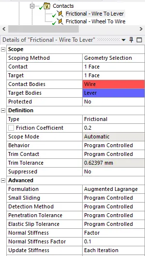
- Select both the contacts and define TYPE = FRICTIONAL > FRICTIONAL COEFFICIENT = 0.1 > FORMULATION = AUGMENTED LAGRANGE > NORMAL STIFFNESS = FACTOR > 0.1 > UPDATE STIFNESS = EACH ITERATION > INTERFACE TREATMENT = ADD OFFSET, RAMPED EFFECTS.
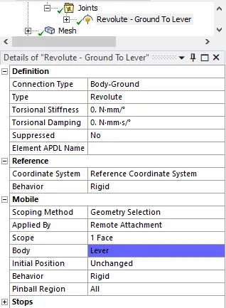
- INSERT > JOINTS > BODY-GROUND > TYPE = REVOLUTE > SCOPE > INNER FACE OF LEVER.
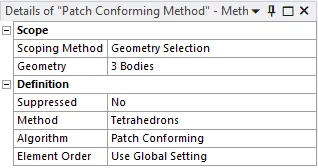
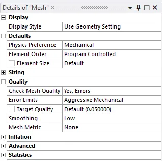
- Now, go to MESH > INSERT > METHOD = TETRAHEDRONS > GEOMETRIES = ALL BODIES.
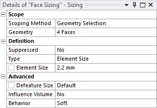
- MESH > INSERT > SIZING > SCOPE = CONTACT FACES > ELEMENT SIZE = 2.2MM.
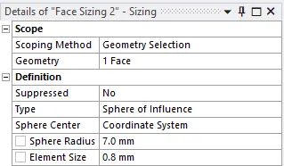
- MESH > INSERT > SIZING > SCOPE = WIRE FACE > TYPE = SPHERE OF INFLUENCE > SPHERE RADIUS = 7MM > ELEMENT SIZE = 0.8MM > GENERATE MESH.
- The mesh will be generated on the model.
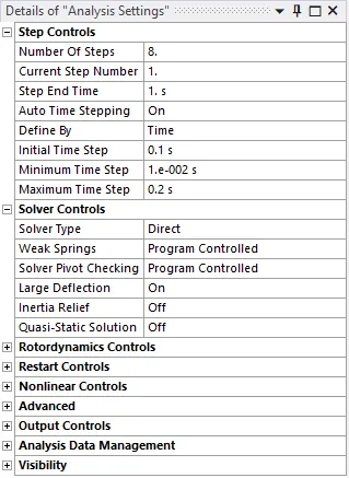
- Then go to STATIC STRUCTURAL > ANALYIS SETTINGS > NO OF STEPS = 8.
- For the first step set TIME STEP = ON > DEFINE BY = TIME > INITIAL TIME STEP = 0.1 > MINIMUM TIME STEP = 1E-2 > MAXIMUM TIME STEP = 0.2.
- Select steps from 2 to 8 and set TIME STEP = ON > DEFINE BY = TIME > CCARRY OVER TIME STEP = ON > MINIMUM TIME STEP = 1E-2 > MAXIMUM TIME STEP = 1.
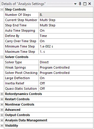
- And set LARGE DEFLECTION = ON > SOLVER TYPE = DIRECT > OUTPUT CONTROLS = YES.
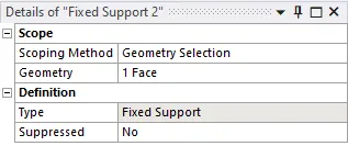
- Go to STATIC STRUCTURAL > INSERT > FIXED SUPPORT > GEOMETRY = INNER FACE OF WHEEL.
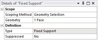
- STATIC STRUCTURAL > INSERT > FIXED SUPPORT > GEOMETRY = END FACE OF WIRE.
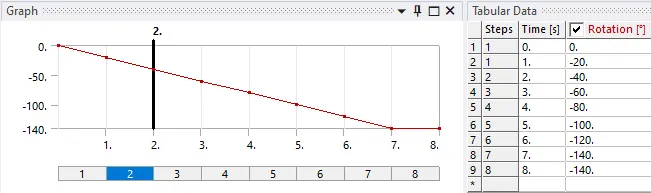
- Then, go to STATIC STRUCTURAL > INSERT > JOINT LOAD > JOINT = REVOLUTE-GROUND TO LEVER > TYPE = ROTATION > DOF = Z > MAGNITUDE = TABULAR DATA.
- Then, go to SOLUTION > INSERT > STRESS > STRAIN > DEFORMATION.
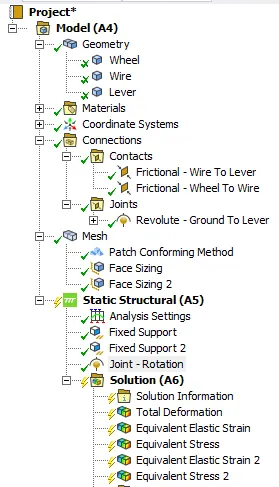
- This will set the output results.
- Then SOLUTION > SOLVE.
- Case 2:
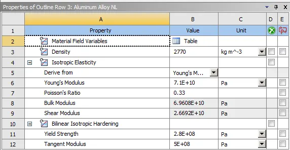
- Create duplicate project of Copper alloy NL and rename as Aluminium alloy NL.
- Then open the mechanical module.
- Go to GEOMETRY > WIRE and assign Aluminium alloy NL material.
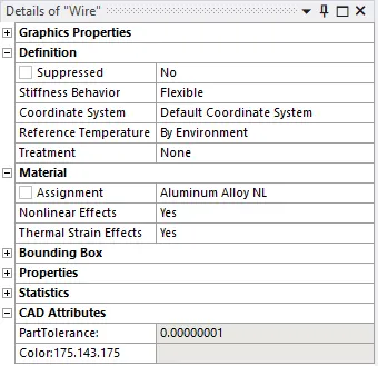
- Then go to SOLUTION > SOLVE.
- Case 3:
- Create duplicate project of Copper alloy NL and rename as Magnesium alloy NL.
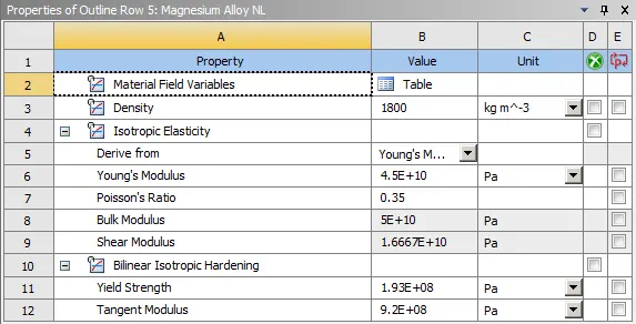
- Then open the mechanical module.
- Go to GEOMETRY > WIRE and assign Magnesium alloy NL material.
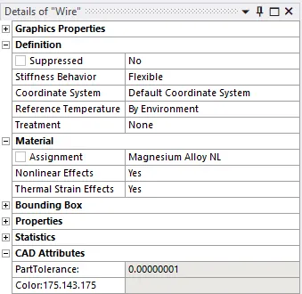
- Then go to SOLUTION > SOLVE.
RESULTS:
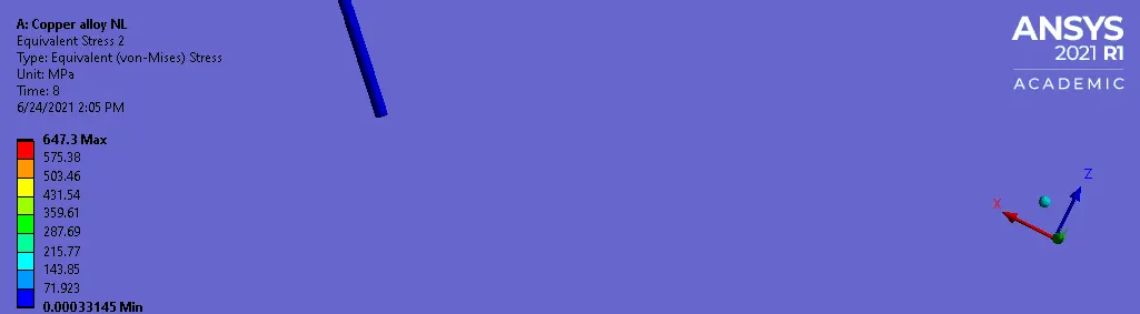
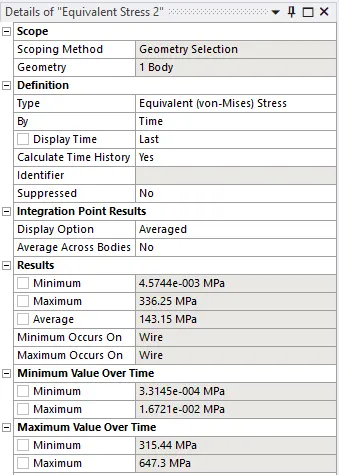
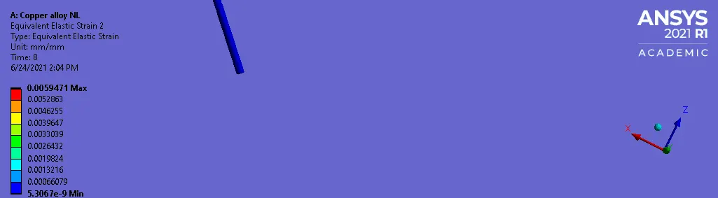
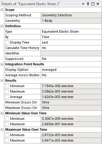
- Case 1(Copper alloy NL):
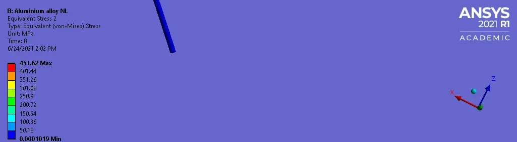
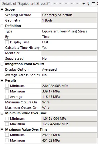
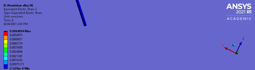
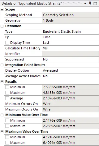
- Case 2(Aluminium alloy NL):
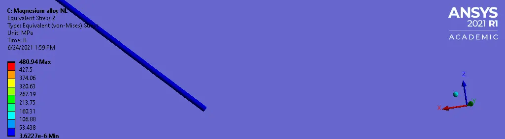
- Case 3(Magnesium alloy NL):
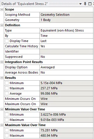
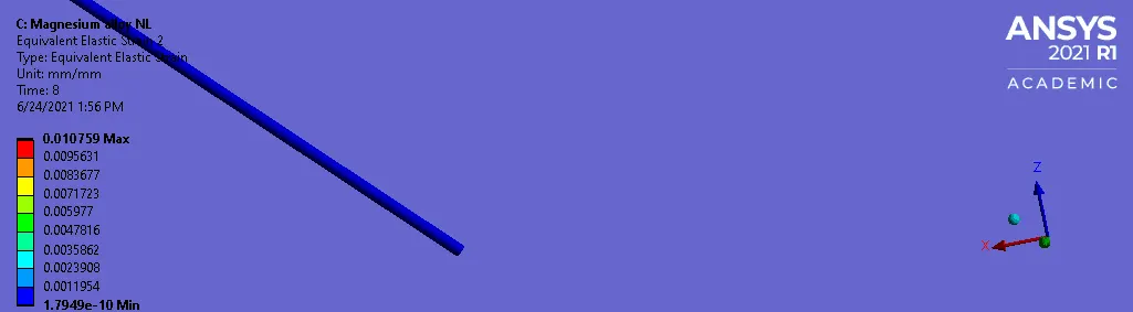
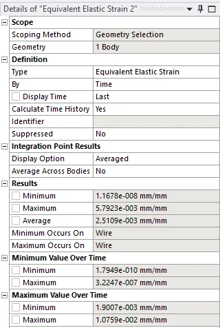
| Stress (Mpa) | Strain (mm/mm) | |
| Copper alloy NL | 336.25 | 3.0862E-3 |
| Aluminium alloy NL | 339.87 | 4.8185E-3 |
| Magnesium alloy NL | 257.27 | 5.7923E-3 |
LEARNING OUTCOMES:
- To add copper alloy NL, aluminium alloy NL and magnesium alloy NL material.
- To assign material from the material library.
- To define contacts for the wheel, lever and the wire.
- To define revolute joint for the lever.
- To deploy mesh on the geometry.
- To define body sizing and face sizing.
- To define fixed support for the wheel and the wire end.
- To define rotation for lever.
- To define output results.
CONCLUSION:
- By performing this project we conclude that Magnesium alloy NL has the least stress and maximum strain rate than the Copper alloy NL and Aluminium alloy NL. The wire bending analysis is performed in ANSYS.