Week 4 -Wire Bending Challenge
-
Objective: To perform an analysis to simulate the bending of a wire using Copper Alloy (Non Linear), Aluminium Alloy (Non Linear) and Magnesium Alloy ( Non Linear) material for the wire and compare the
results.
- Procedure:
Open the static structural analysis system in the Project schematic. Rename it to wire_bending. The material used for analysis is Copper Alloy (NL), Aluminium Alloy (Non Linear) and Magnesium Alloy ( Non
Linear). These materials are added to the material library in Engineering Data. Now proceed to import the Geometry. Import the Geometry. Open the Geometry in SpaceClaim. Ensure the geometry is
properly imported by doing quick visual inspection. The geometry is found to be okay.
Update and open the mechanical module. As seen below, one send of the wire is inside the wheel. The wheel is supposed to be fixed. On the other hand, we will rotate the lever so that the wire is bend
around the wheel.
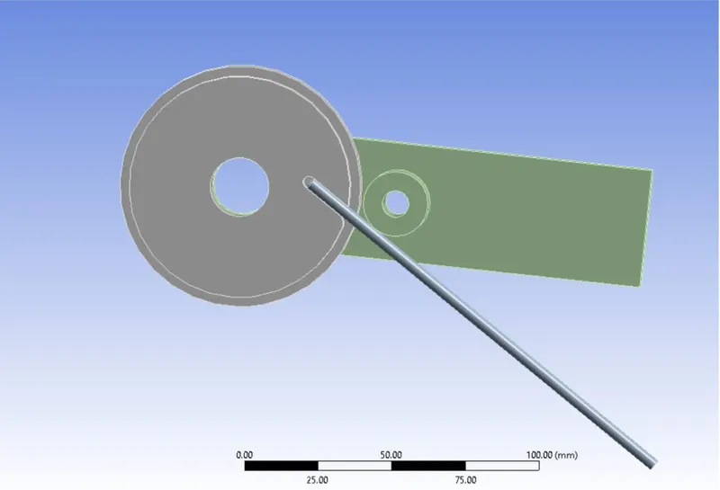
The Ansys automatic contact detection has detected some initial contact between the wheel, wire and the lever. The contact between the roller, wire and the lever need to be updated. The first contact is
defined between the wire and the lever. For Contact Bodies, wire is selected, and for Target Bodies, lever is selected. Define the second contact pair between the wire and the wheel with wire as the Target
Body and the wheel as the Contact Body.
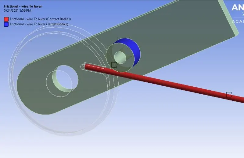
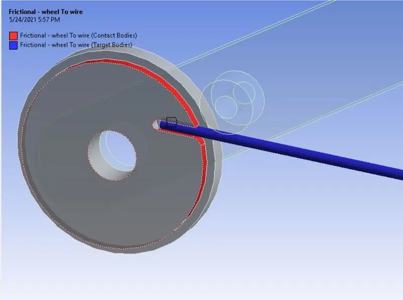
Frictional type contact is used with coefficient of friction as 0.2. Following contact settings is defined.
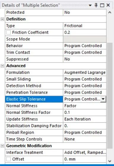
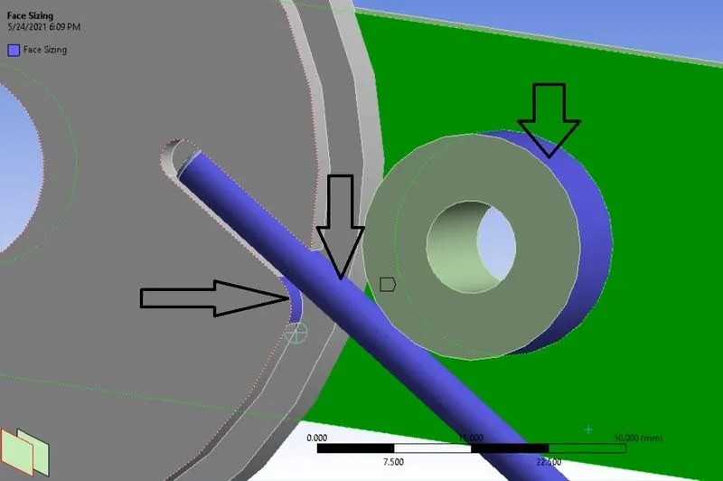
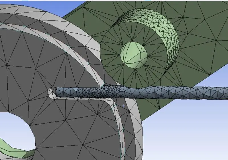
The body is to be meshed with tetrahedron elements. So go to Mesh > Insert > Method. Select Method as Tetrahedrons. Using mesh sizing, mesh the part of the lever which will be in contact with the wire,
the wire, and the curved part of the wheel where the wire will start bending with element size of 2.2 mm. These portions are shown below:
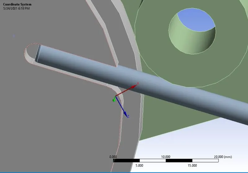
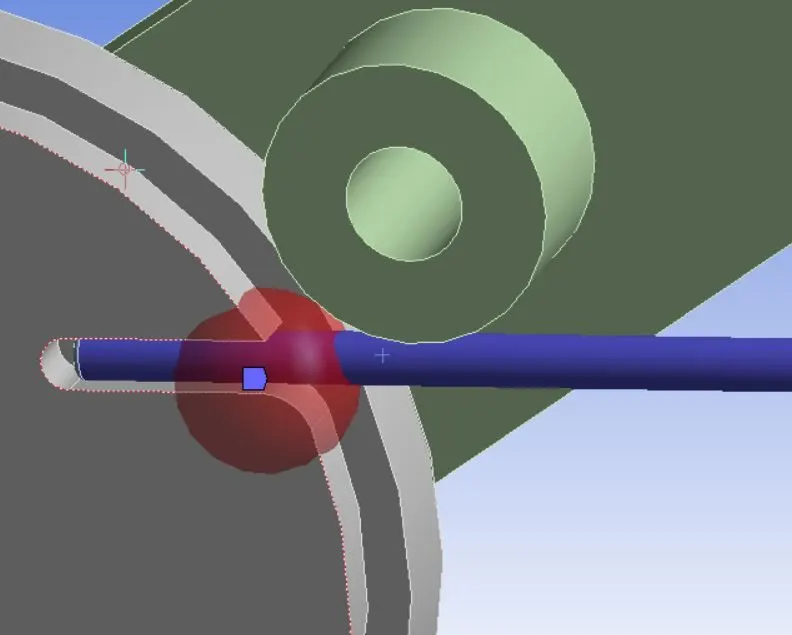
To refine the mesh in the crucial region, define mesh sizing 0.8 mm using sphere of influence. For that, first insert new coordinate system. Right click on the curved surface of the wheel and click on Create
new co-ordinate system. Give X offset of 3 mm and Z offset of -3 mm to the created co-ordinate system.
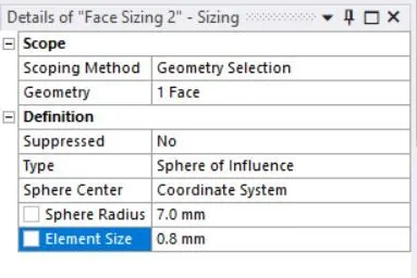
Go to Mesh > Insert > Sizing. Select the outer surface of wire in the Geometry selector. Select type as Sphere of influence. For the sphere centre, select the newly created co- ordinate system. Use element
size of 0.8 mm. Generate the mesh.
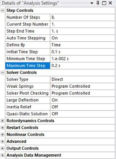
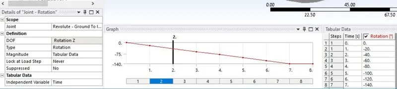
The lever is to be rotated. Instead of giving this rotation in one single step, the rotation is divided into 8 steps. Define the load steps. Go to Analysis Settings. Enter no. of steps = 8. For the 1st step, following
setting is used:
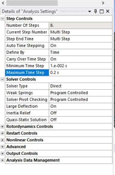
For 2nd to 8th loadstep, the following setting is used:
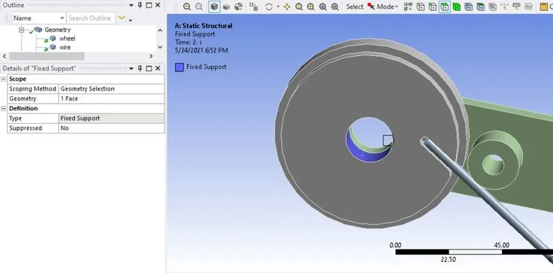
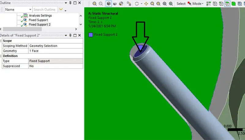
Now insert the fixed support for the wheel and the end of the wire which is inside the wheel, so that the wire does not slide out of wheel during bending. Go to Statical Structural > Insert > Fixed Support and
fix the wheel as shown below:
Similarly, insert fix support at the end of wire inside the wheel as shown below:
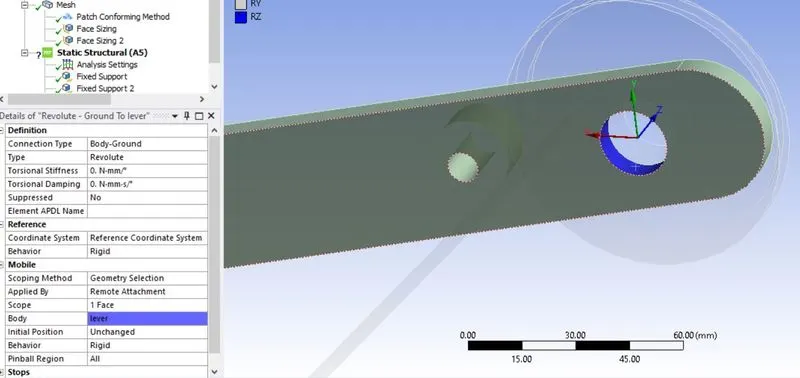
Define Revolute joint for the lever. Go to Connections > Insert > Joint. Define the joint as shown below:
Now define the joint load for the revolute joint. Go to Statical Structural > Insert > Joint load. Select the Ground to Lever joint. Select Type as rotation. For magnitude, give rotation in steps using tabular
format as shown below:
The case setup is now completed. Run the simulation and view the stress and strain in the wire alone.
- Results:
1. For wire with material copper alloy:
Stress contour:
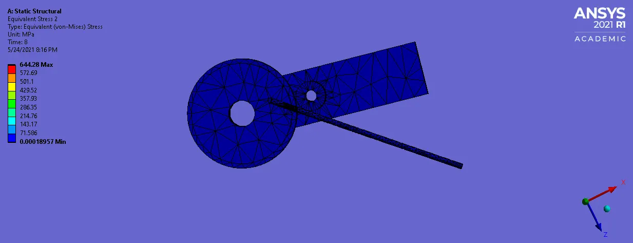
Stress in the wire:
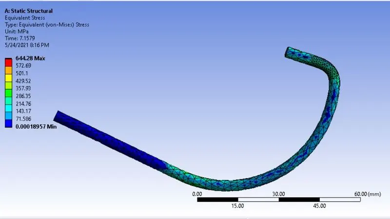
Max stress of 644 Mpa is observed in the wire.
Strain in the wire:
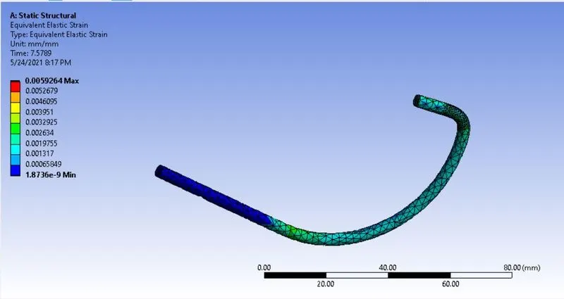
Max strain of 0.005 is observed.
2. For wire with material aluminium alloy:
Stress Contour:
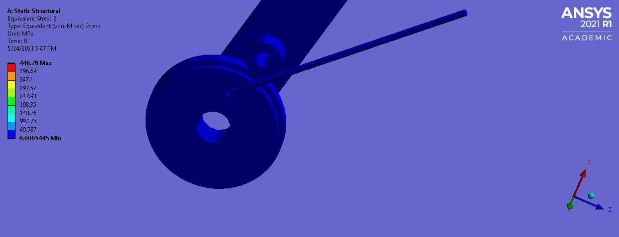
Stress in the wire:
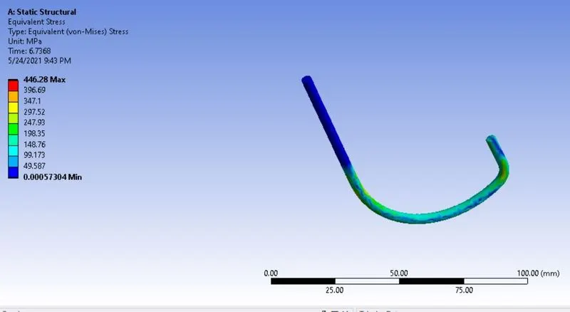
Max stress of 446.28 is observed in the wire.
Strain in the wire:
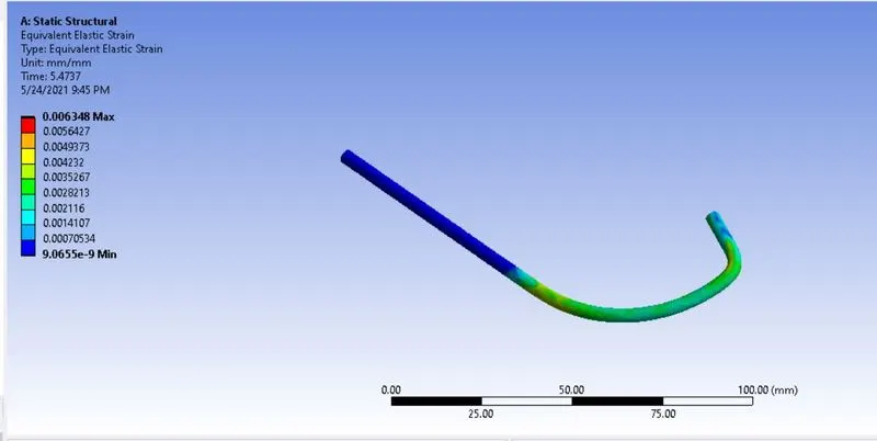
Max strain of 0.006 is observed.
3. For wire with material aluminium alloy:
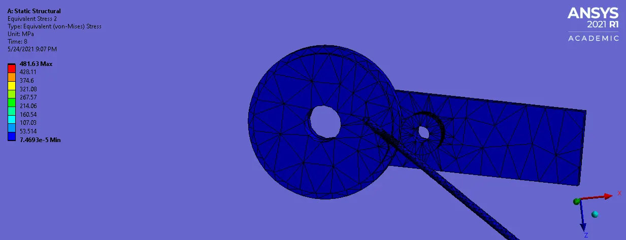
Stress in the wire:
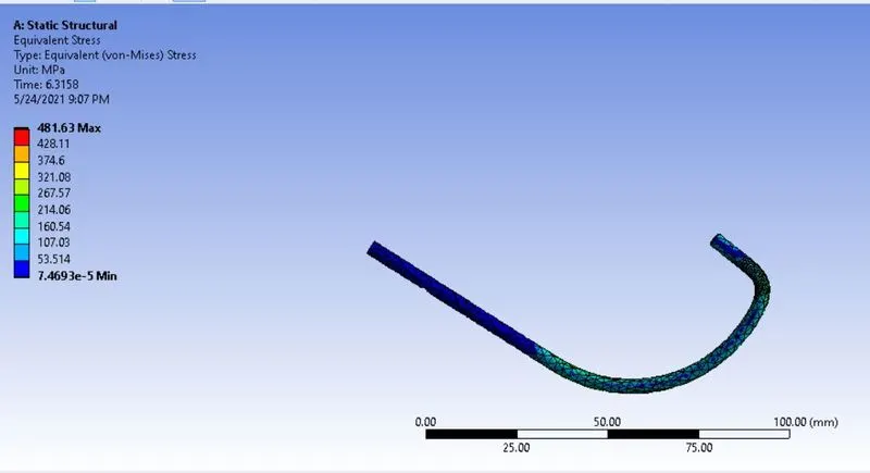
As seen, max stress of 481.6 is observed.
Strain in the wire:
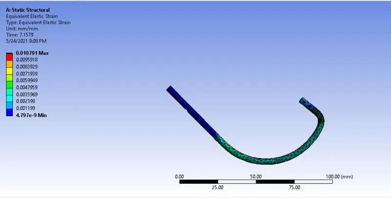
As seen, strain of 0.010 is observed.

Thus, highest stress is observed in the wire with Copper alloy material, followed by Magnesium alloy and then Aluminium alloy.
- Conclusion: Thus, the given simulation is successfully completed and results are compared. The methd of refining mesh in the critical area using face sizing with sphere of influence is also learned.