Week 4 -Wire Bending Challenge
Obejective: To perform an analysis to simulate the bending of a wire using materials as Copper Alloy (Non Linear), Aluminium Alloy (Non-Linear), and Magnesium Alloy (Non-Linear) for the wire.
Procedure:
Step 1: Engineering Data
- For this analysis we will be using different materials and analyzing the results.
- Add Copper Non Linear as Material to drop down list. Similarly add Aluminium Alloy (Non-Linear), and Magnesium Alloy (Non-Linear).
Step 2: Geometry
- Right click on geometry and Import the Skill_Lync_Wire bending model.x_t extension file
- Rename the Static Structural tab as Wire Bending.
- Update the Static Structural tab and proceed to model.
Step 3: Connections
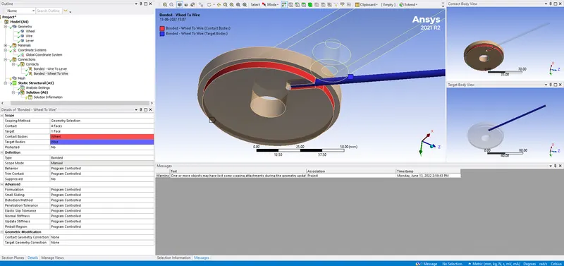
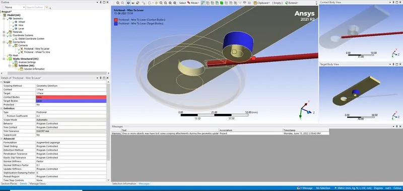
- Assign Frictional Contact from Wire to Lever and Wheel to wire as shown below
- Assign Frictinal coefficient of 0.2, formulation method as Augmented Lagrange, Normal Stiffness factor as 0.1 and interface treatment as add offsets, Ramped effects.
Step 4: Meshing
- Open Meshing and add Tetrahedron meshing method to all the bodies.
- Insert Face sizing for wire the drum and the edge in contact as shown below with element size as 2.2mm.
- Reduce the smoothenig to Low
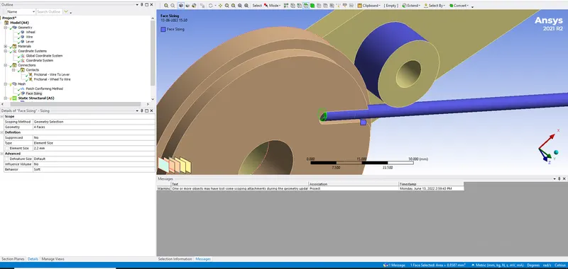
- Right click on the edge of the contact shown below and insert coordinate system. Add X-offset (3mm) and Z-offset (-3 mm) to move the coordinate system to desired location.
- Now insert Face Sizing for Wire surface face defined by sphere of influence type with coordinate system as centre of sphere. keep sphere radius as 7mm and element size as 0.8mm
- Generate the mesh.
Step 5: Setup
- In analysis settings we are going to simulate this case in 8 steps.
- For the first step turn on auto time stepping defined by time, 0.1 as intial step, 1e-2 as minimum and 0.2 as max time step. Change solver type to Direct with program controlled Weak springs and large deflection turned on. Change output controls to yes.
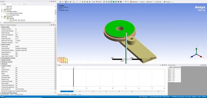
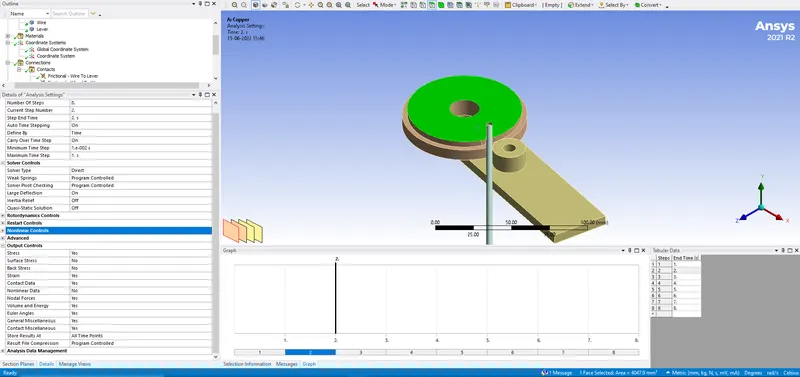
- Insert Fixed support on inner circular surface of wheel.
- Insert Revolute joint to inner circular surface of lever and define coordinate system as shown below.
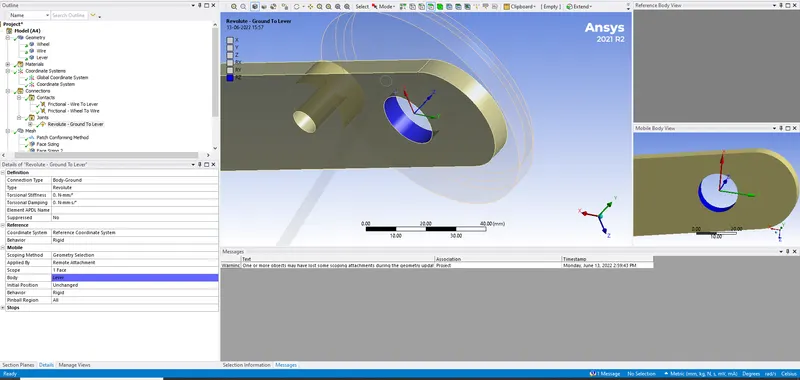
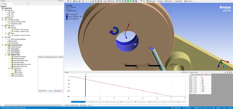
- Insert joint load as rotating type in analysis setting defined by tabular data in increments of -20 deg.
- Insert Fixed support to the end of wire to avoid slipping of wire.
Step 6: Solution
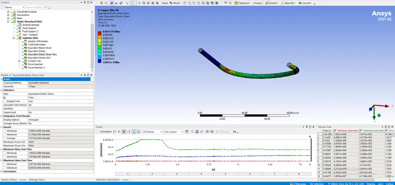
- Insert results for Equivalent Strain, Equivalent Stress distribution, Total Deformation for each geometry in focus to observe the values and data.
Results and Conclusion:
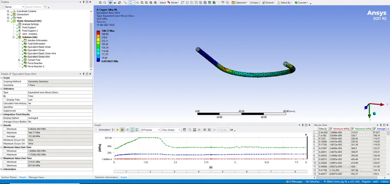
Results for Case 1:
| Material | Eq Stress Avg | Eq Strain Avg |
| Units | MPa | mm/mm |
| Copper Alloy NL | 348.17 | 0.0031793 |
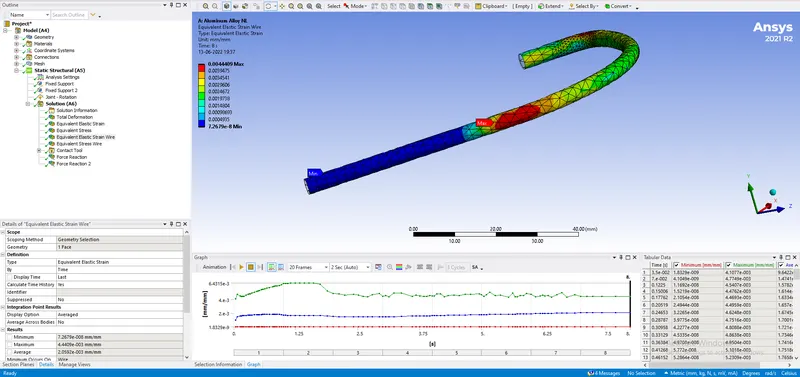
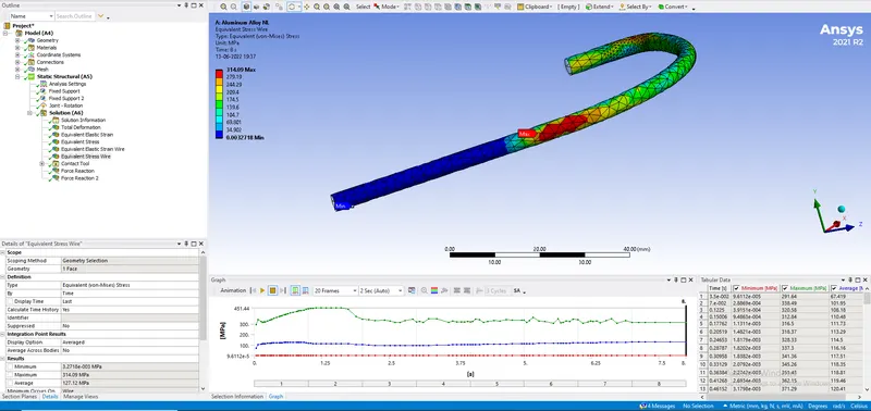
Results for Case 2:
| Material | Eq Stress Avg | Eq Strain Avg |
| Units | MPa | mm/mm |
| Aluminum Alloy NL | 314.09 | 0.0044409 |
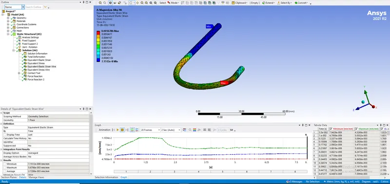
Results for Case 3:
| Material | Eq Stress Avg | Eq Strain Avg |
| Units | MPa | mm/mm |
| Magnesium Alloy NL | 254.32 | 0.0056786 |
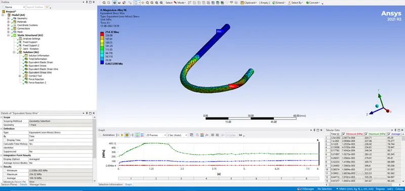
Result Comparison:
| Material | Eq Stress Avg | Eq Strain Avg |
| Units | MPa | mm/mm |
| Copper Alloy NL | 348.17 | 0.0031793 |
| Aluminum Alloy NL | 314.09 | 0.0044409 |
| Magnesium Alloy NL | 254.32 | 0.0056786 |
Conclusion:
The equivalent stress in copper wire is highest followed by Aluminum and Magnesium alloy.
But the equivalent strains induced in Magnesium alloy is highest followed by Aluminum and Copper.