Week 4- Rolling operation
AIM:
For this challenge, you will have to simulate the rolling operation on a workpiece made of copper. The model will be provided to you. Increase the length of the workpiece by 60mm and decrease its size on both sides by 8mm. Run the simulation for 14 steps and you can give small but random values( similar to the ones mentioned in the video) for the displacement. Ensure that the edge of the workpiece is displaced by 90mm.
Find out the
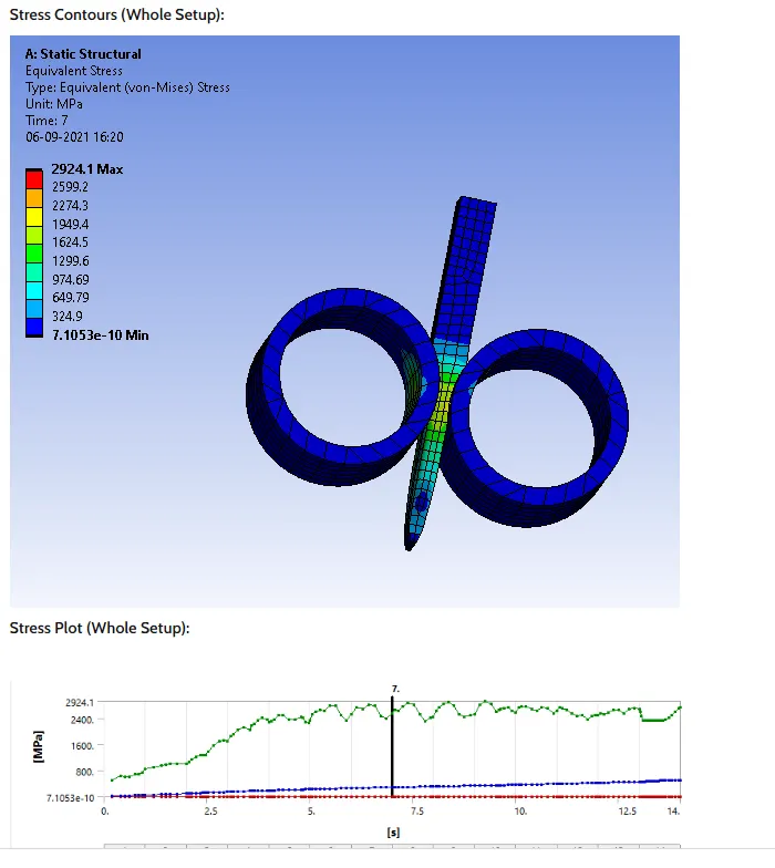
- Equivalent stress for the whole setup
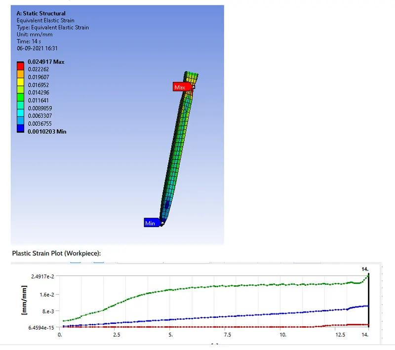
- Equivalent Plastic strain for the workpiece
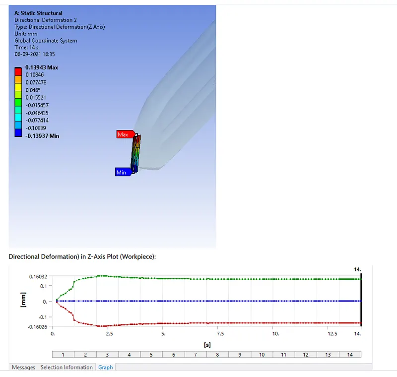
- Directional Deformation in the Z axis for the workpiece
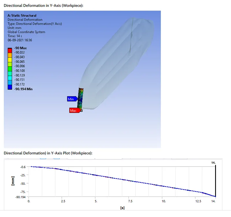
- Prove that the workpiece has displaced by 90mm (Hint: It's mentioned in the video)
Procedure:
- Open the Ansys work Bench and import the given model.
- We should have to give the material in the engineering data the material used for the work piece is Copper Alloy NL and we should update the engineering data.

- We should have to edit the Geomentry in the given model as per the given dimensions .
- we should click on the Geomentry>Edit space claim >edit the model increasing the height of the work piece 60mm and decrease the sides of the length of 10mm both sides of the work piece.
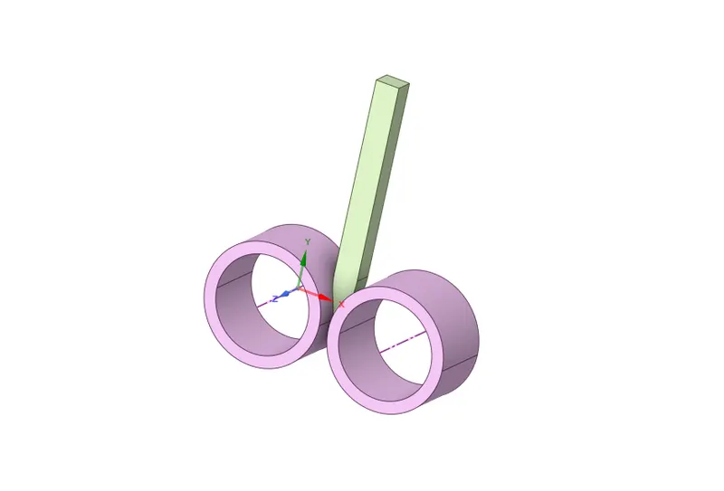
- We should have to edit the model in the Work bench clcik on the model and edit the model.
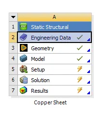
- we should have to rename the parts as per the names as Wheel 1,wheel 2, Work piece.
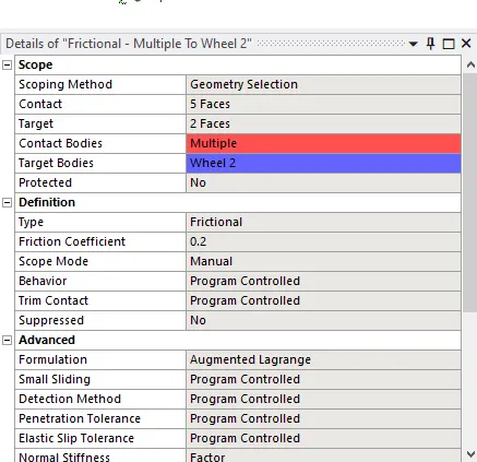
- we should have to flip the both contact surfaces define according the defination. we should have to Select the Contact bodies and Target Bodies of the both surfaces and we should have to give the Augmented and values to the model.
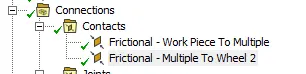
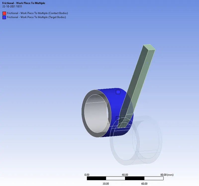
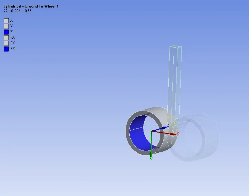
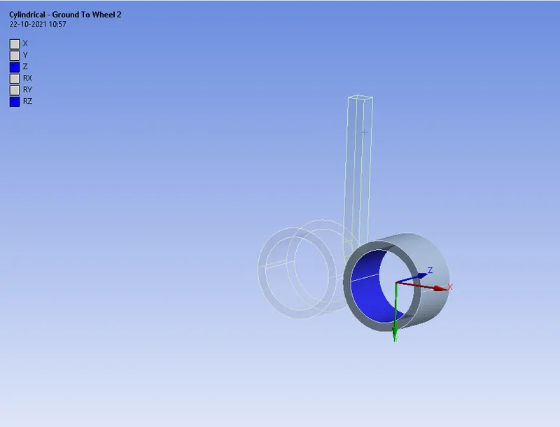
- we should have to give the Joints to the wheel go to the Joints>cylinder>Wheel 1 >change the Refernce geomentry direction and select the faces of the model. We should have to follow the same to the wheel 2 in the model
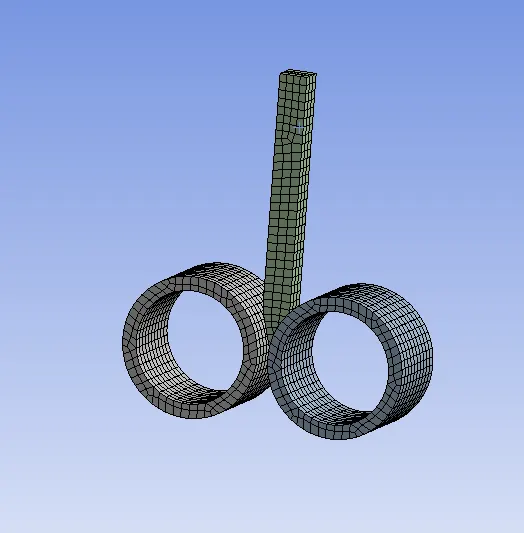
- We should have to give the mesh generation to the model and having the mesh size of 3mm for the fine mesh.
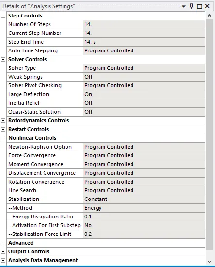
- we should have to give the Boundary condtions to the given model in the Analysis setting of the Time step and large deformations and normal stiffness.
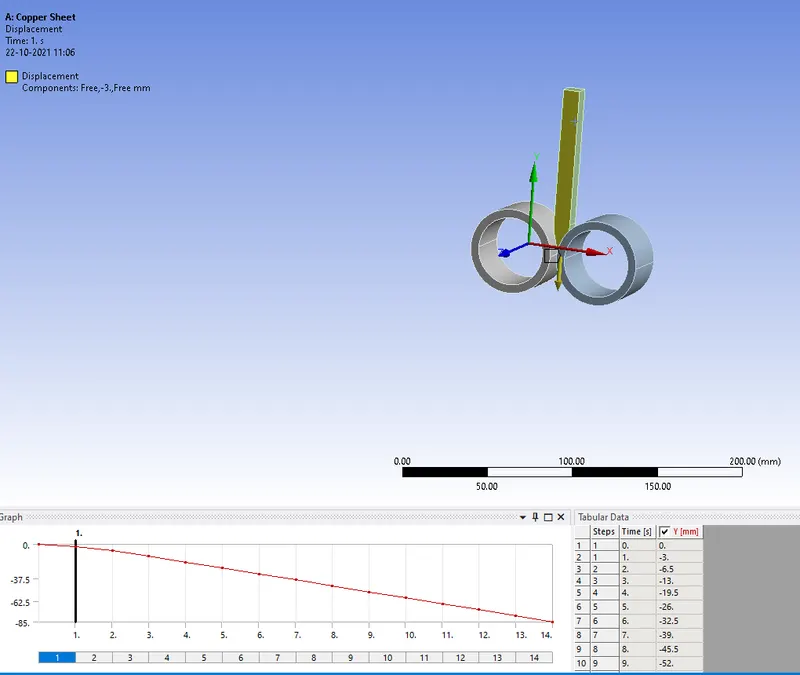
- we should have to give the displacements of thr work piece and asssign the Y direction values of the given model.
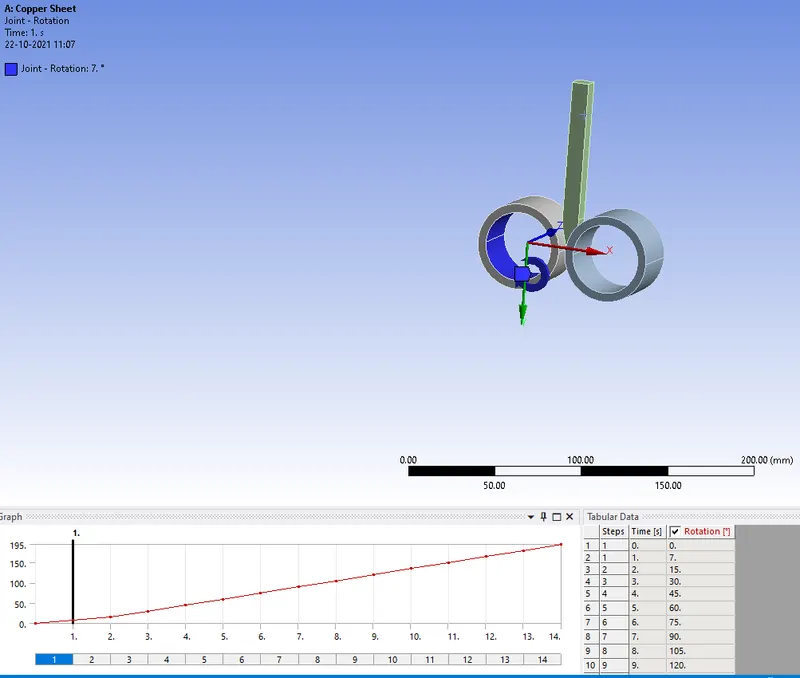
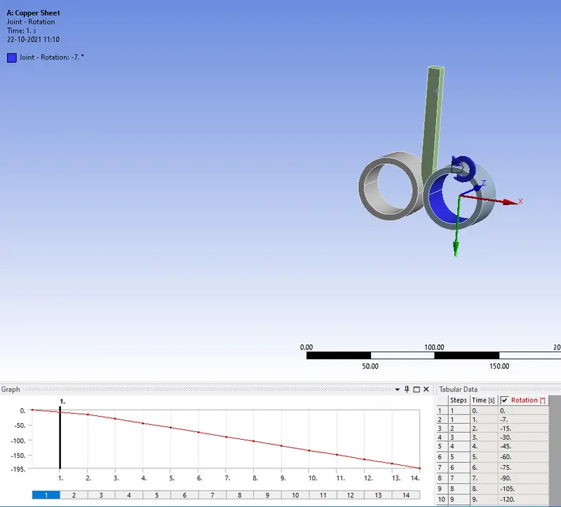
- We should have to give the Rotation of the both wheels and we should have to assign the values in the model in the Rotation direction.
- we should have to give the Stress,plastic strain Directional deformation in Z direction and Y direction of the model.
Results:
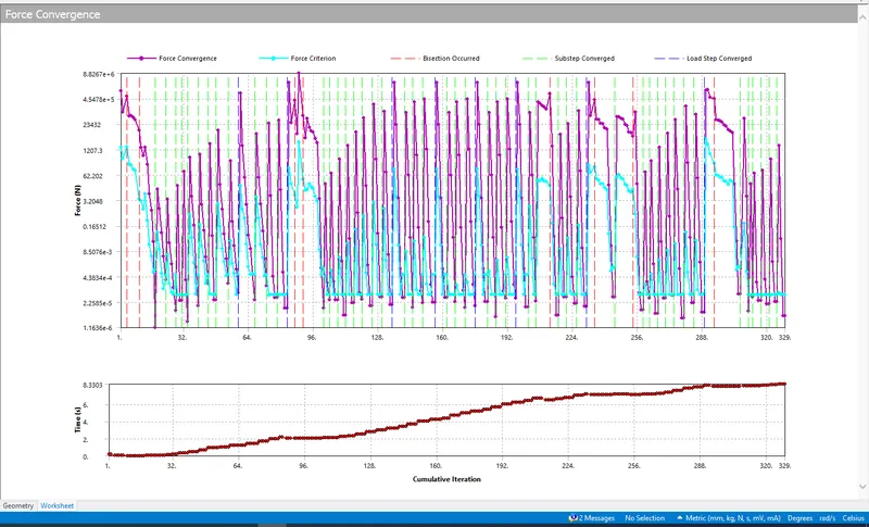
Force Convergence:
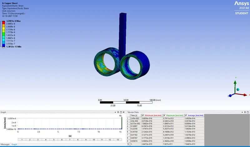
Strain
Stress
Plastic Strain
Deformation in Z direction
Conclusion:
This study of the rolling process drew every minute aspect. In terms of manufacturing engineering, every engineer should consider the rolling
process as a core metal forming process. This process is mainly used when a cross-sectional area of a material required to be changed by an
engineer.