Week 4- Rolling operation
AIM:
Simulate the rolling operation on a workpiece made of copper and evaluate the results provided with diffrent parameters.
OBJECTIVE:
The main purpose of this challenge is to simulate the rolling bar operation on a workpiece made of copper, making some geometry changes and then running the simulation for 14 steps by giving random values for the displacement but the workpiece should be displaced up to 90mm.
PROCEDURE:
. Select Static Structural, drag and drop into Project Schematic.
. Choose material as Copper Alloy NL, under Engineering Data.
. Under geometry tab, import the given roller & workpiece geometry, double-click to open Space Claim and change the dimensions of the workpiece i.e length of the workpiece by 60mm and decrease its size on both sides by 8mm .
. Then in Mechanical Module, assign Copper Alloy NL to the workpiece. The roller wheels can remain at structural steel.
. Assign a frictional connection between the rollers and workpiece with coefficient of friction = 0.2.
. Add 2 cylindrical joints to both wheels.
. The mesh size was set to 4mm, but the workpiece was given 2mm mesh sizing.
. Under static structural tab, we set the analysis to 14 steps with auto timestep as programmed
. A displacement on 90mm in 14 steps is given along Y axis for the workpiece.
. Joint loads in CW and CCW directions are given for the two wheels respectively. (up to 195deg rotational motion about Z-axis)
. Directional Deformation in Z-axis, Equivalent Plastic Strain and Equivalent Stress plots are requested from the solver as outputs.
. Directional Deformation in Y-axis to prove the workpiece travels for 90mm.(in this case it is -ve y axis).
. Run the simulation by clicking on SOLVE.
The below conditions and settings applied to the model.
MATERIAL PROPERTIES (COPPER ALLOY NL)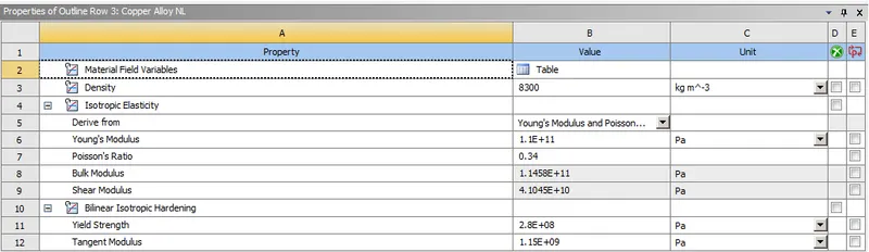
MATERIAL PROPERTIES (STRUCTURAL STEEL)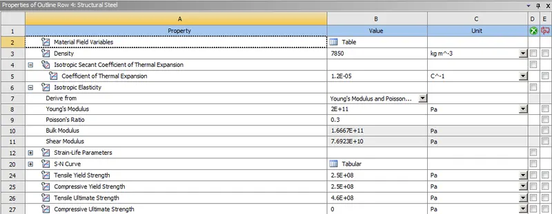
CONTACTS
CONTACT 1: Frictional contact between workpiece to wheel 1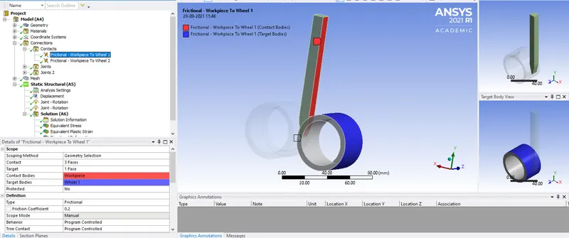
CONTACT 2: Frictional conatct between workpiece and wheel 2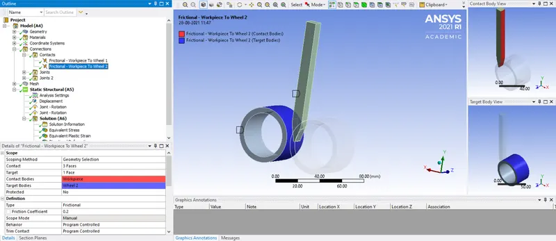
JOINTS
JOINT 1: Ground to wheel 1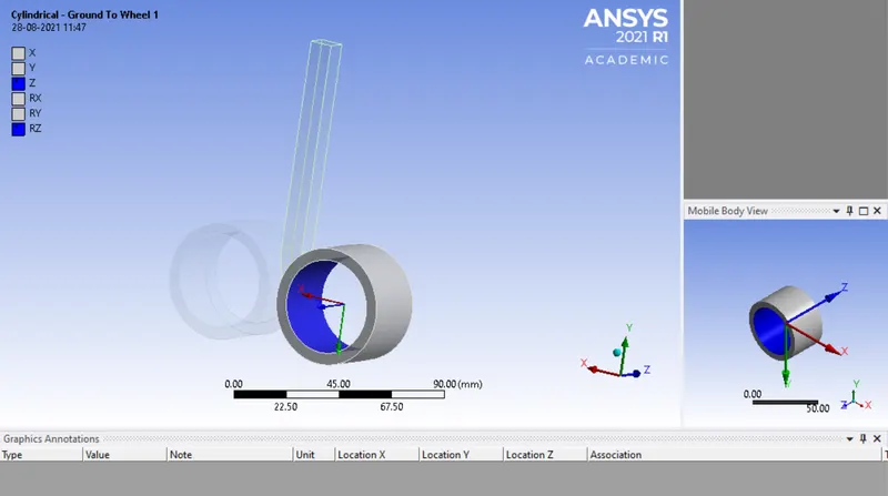
JOINT 2: Ground to wheel 2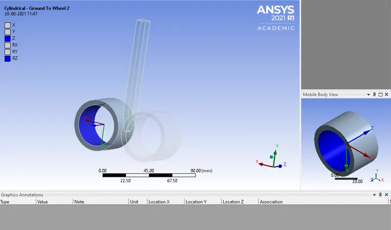
LOADS:
DISPLACEMENT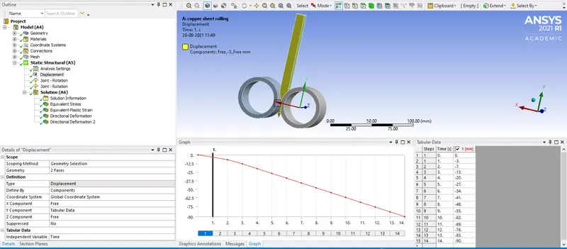
JOINT ROTATION 1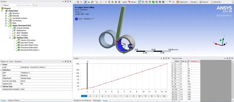
JOINT ROTATION 2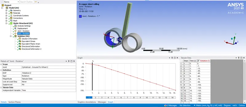
MESHING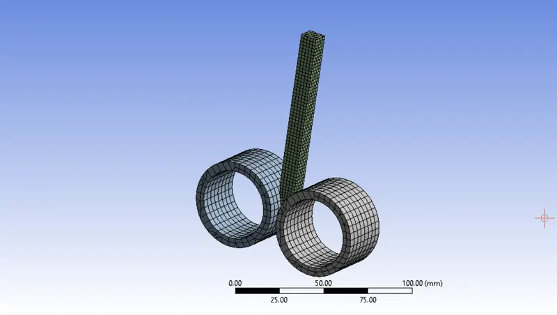
RESULTS:
EQUIVALENT STRESS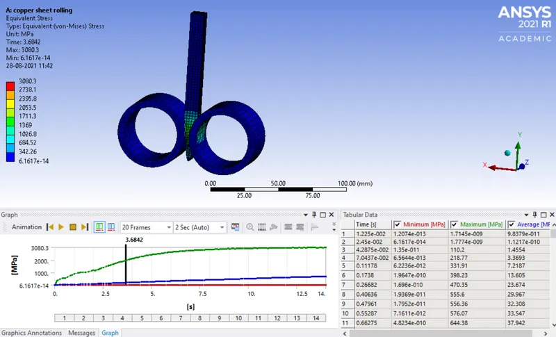
EQUIVALENT PLASTIC STRAIN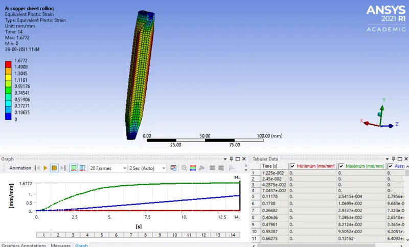
DIRECTIONAL DEFORMATION (Y- AXIS)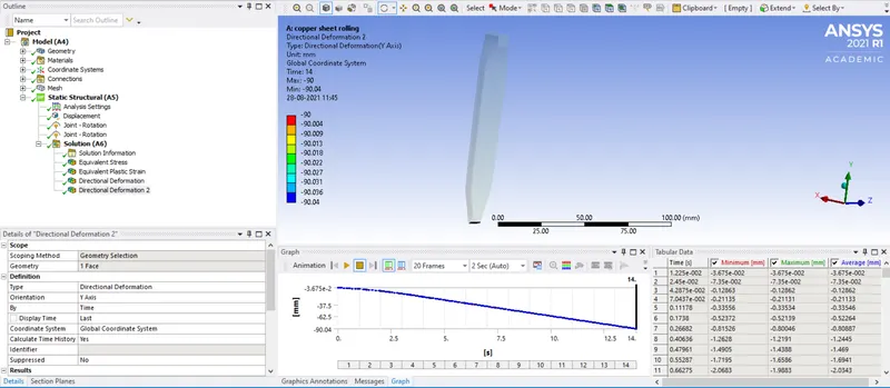
DIRECTIONAL DEFORMATION 2 (Z-AXIS)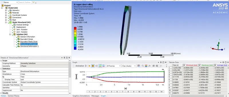
RESULTS SUMMARY:
The directional deformation i.e on y axis proove that the workpiece is displaced by 90mm in negative y direction as shown in the images above.