Week 5 Bending of iPhone
SIMULATION OF BENDING OF iPHONE
OBJECTIVE
Case 1 : To simulate bending of an iPhone and obtain the results for simulation
Case 2 : In the model,
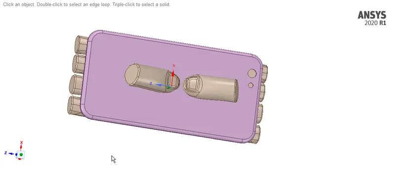
- Relocate the bottom pushing fingers by inputting the values, X = 22.5mm and Z = 10mm
- Define the S-N curve for the Aluminium Alloy material as per values given below and determine the fatigue life results
|
Stress, MPa |
Number of Cycles, N |
|
225 |
10000 |
|
175 |
100000 |
|
143 |
1000000 |
|
110 |
10000000 |
|
80 |
100000000 |
Also determine,
- Directional deformation for the model
- Factor of Aluminium Alloy NL
- Life of the Aluminium alloy for the case
Finally, Compare the results and present with the conclusion.
MODEL SETUP
The 3D model of the setup is imported into ANSYS Space Claim. Check for any abnormalities in the Geometry.
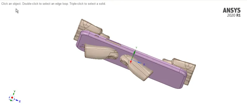
For Case 1: Pre defined setting of the model:
For Case 2: Bottom pushing fingers are relocated by inputting the values, X = 22.5mm and Z = 10mm
MATERIAL ASSINGMENT:
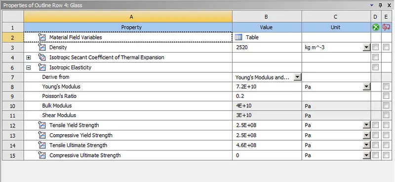
- Glass is assigned for the Display
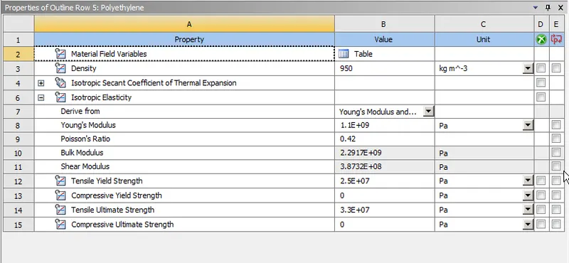
- Polyethylene is assigned for the Insides of the iPhone
- Al Alloy NL is assigned for the Frame
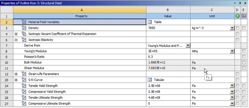
- Structural Steel is assigned for the fingers
The properties of various materials used are shown below
- Glass : Values are modified from the Polyethylene material data
- Polyethylene :
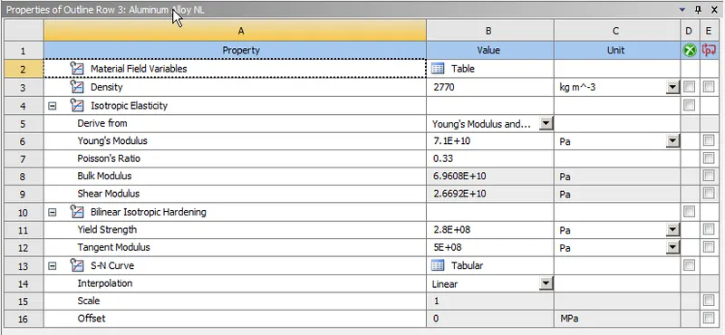
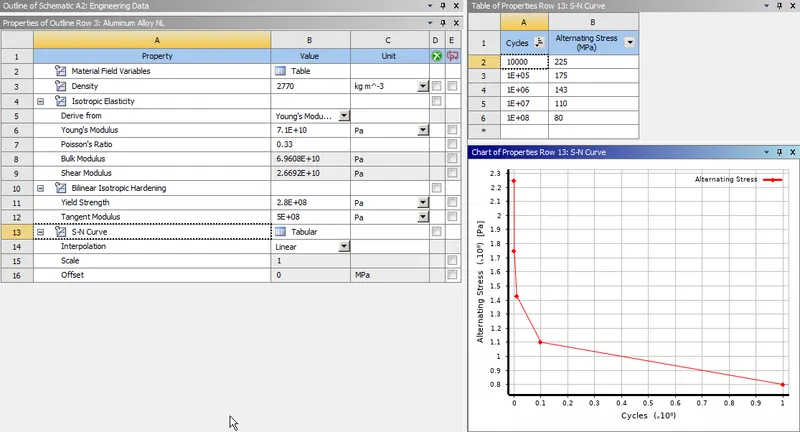
- Al Alloy NL : Defining the S-N curve for the Aluminium Alloy material as per values given below,
|
Stress, MPa |
Number of Cycles, N |
|
225 |
10000 |
|
175 |
100000 |
|
143 |
1000000 |
|
110 |
10000000 |
|
80 |
100000000 |
- Structural Steel :
MODEL SETUP:
After importing the Geometry, rename the Parts and
- Assign Stiffness behaviour as rigid to all the Top 8 Fingers and left bottom pushing fingers
- Assign Flexible Stiffness behaviour to the right bottom pushing finger
CONTACTS DEFINITION:
We need to define contact region for this model.
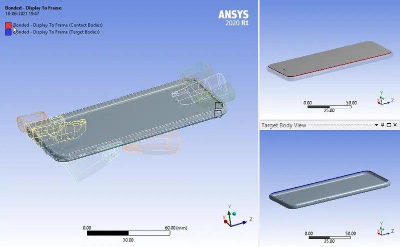
- Bonded contact between Display and the frame
- Frictionless contact between Display and the insides
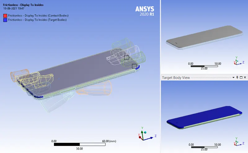
- Frictionless contact between the frame and the insides
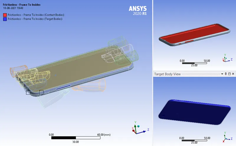
- Frictionless contact between all the bottom surface of the Top 8 fingers and and the Display
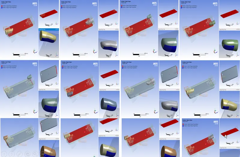
- Frictionless contact between all the bottom surface of the bottom pushing fingers and and the Frame
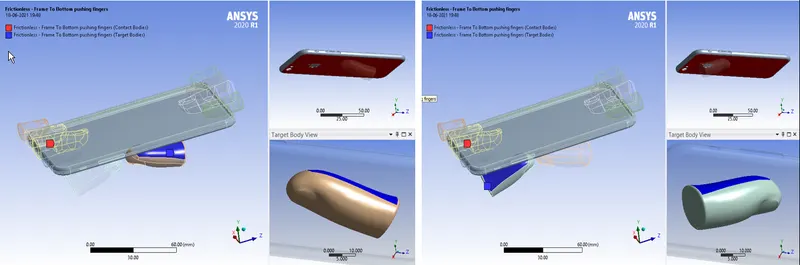
JOINT DEFINITION:
We need to define several joints for this setup
- Fixed joint between all the Top 8 fingers and the Display
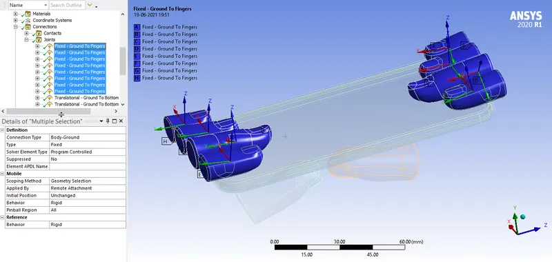
- Translational joint between the two bottom pushing fingers and the frame
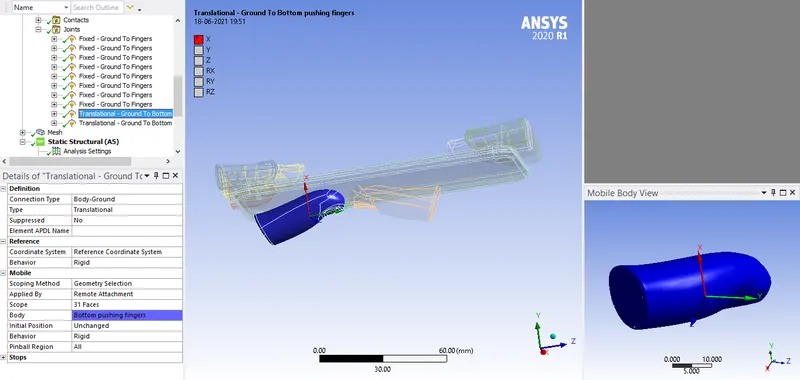
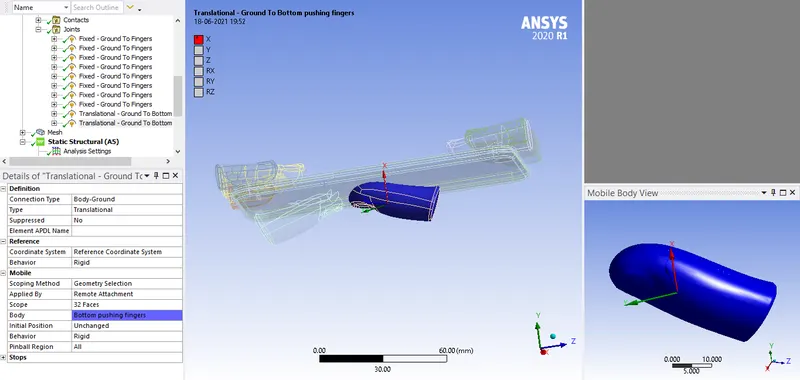
Make sure the co-ordinate system for the bottom pushing fingers are same for both bottom fingers as shown above
MESHING:
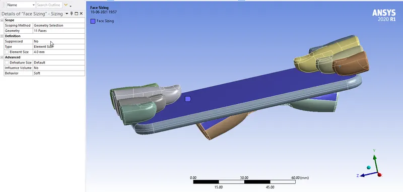
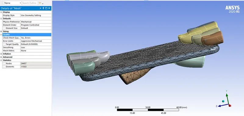
The setup has been meshed as shown below
A face sizing of element size 3 mm is selected for
- Bottom surface of bottom pushing fingers
- Frame
- Display
ANALYSIS SETTINGS:
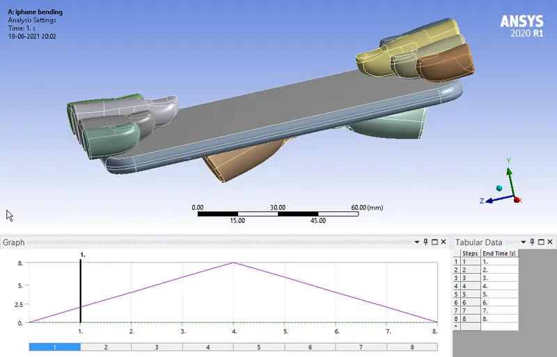
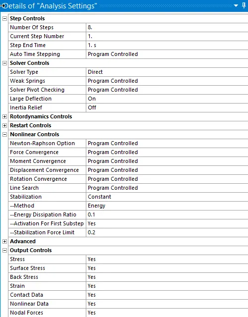
Now, the simulation is run for 8 steps. The following settings are modified
Auto Time stepping is set to Program Controlled.
Solver Type is set to Direct
Weak springs are set to Program Controlled
The Large deflection is set to ON.
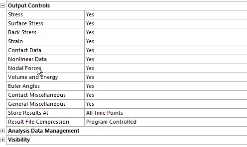
Other settings are as shown below
BOUNDARY CONDITIONS:
The boundary condition for this model are
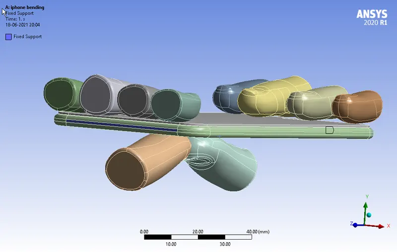
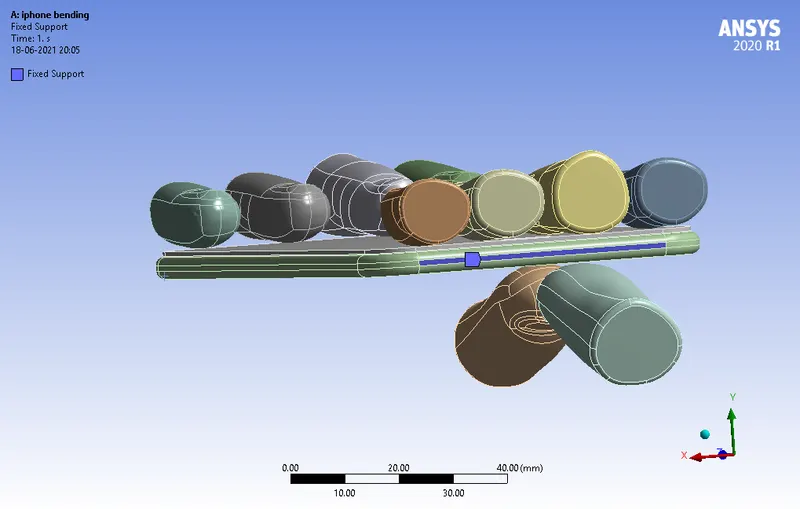
- A fixed support on the sides of the insides :
This is done because to ensure that the insides doesn’t fly off while simulation
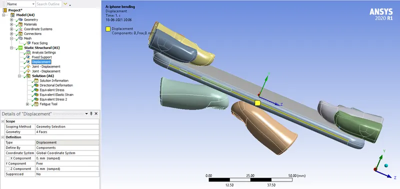
- Displacement on the sides of the frame :
The Y component is set free as the model deforms in that axis and X, Z components are fixed.

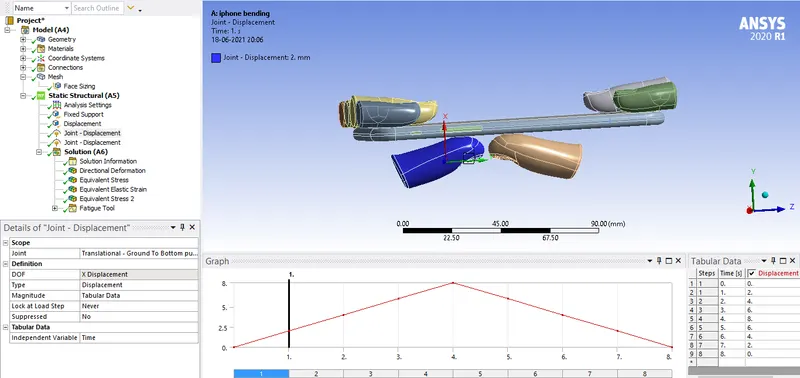
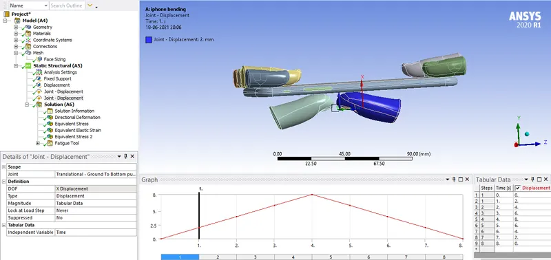
- Displacement on both the bottom pushing fingers :
Displacement in the X axis is given for both the bottom fingers to 8 mm and then retracting back.
RESULTS:
CASE 1:
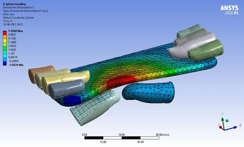
- Directional deformation for the model:
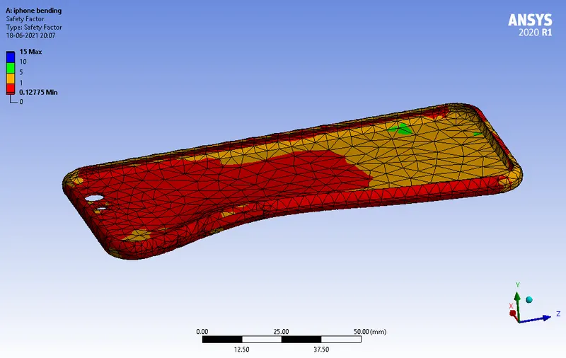
- Factor of Aluminium Alloy NL:
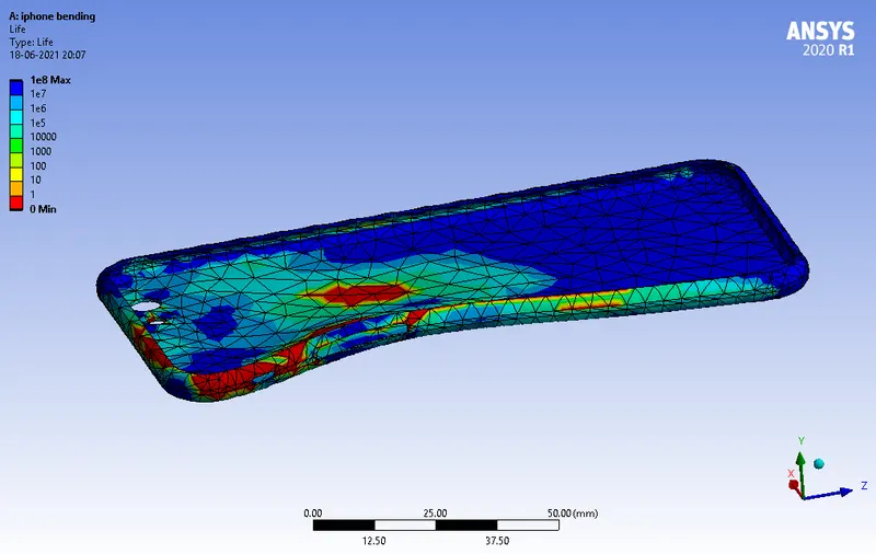
- Life of the Aluminium alloy for the case:
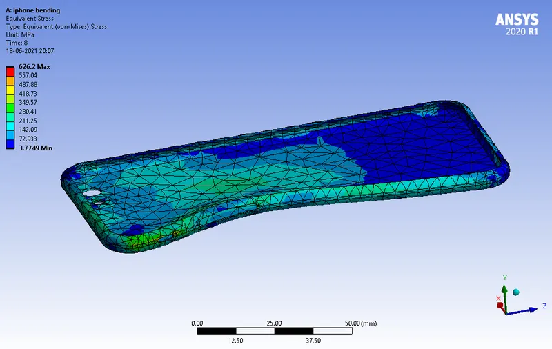
- Equivalent Stress of the Frame:
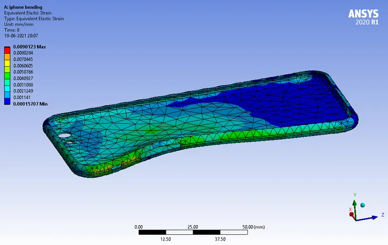
- Equivalent Elastic Strain of the Frame:
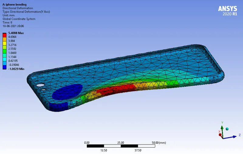
- Directional deformation in the Y axis for the Frame:
CASE 2:
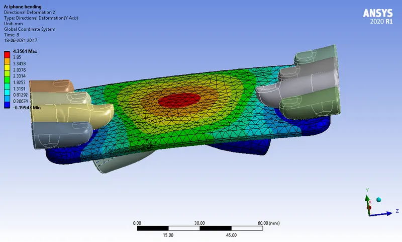
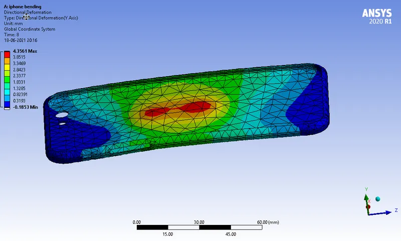
- Directional deformation for the model:
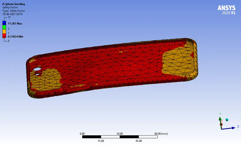
- Factor of Aluminium Alloy NL:
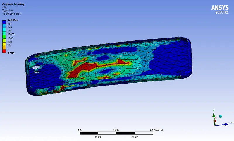
- Life of the Aluminium alloy for the case:
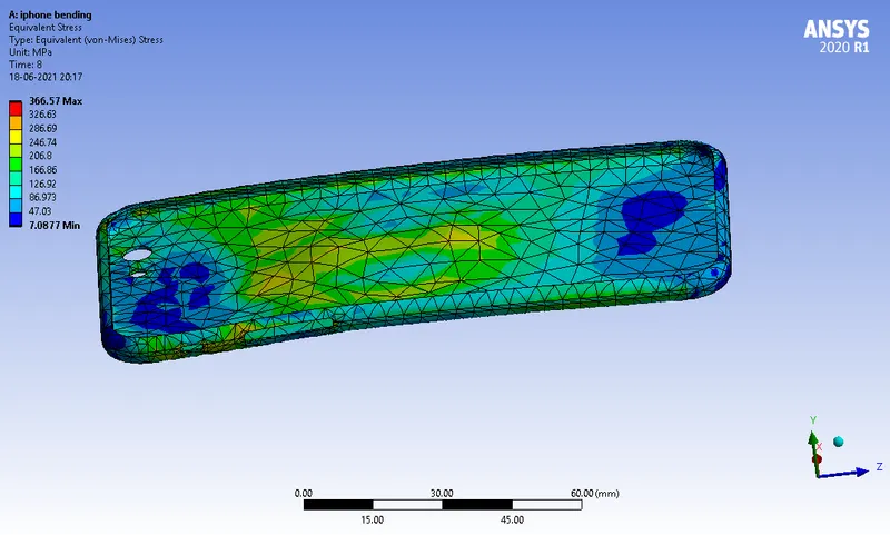
- Equivalent Stress of the Frame:
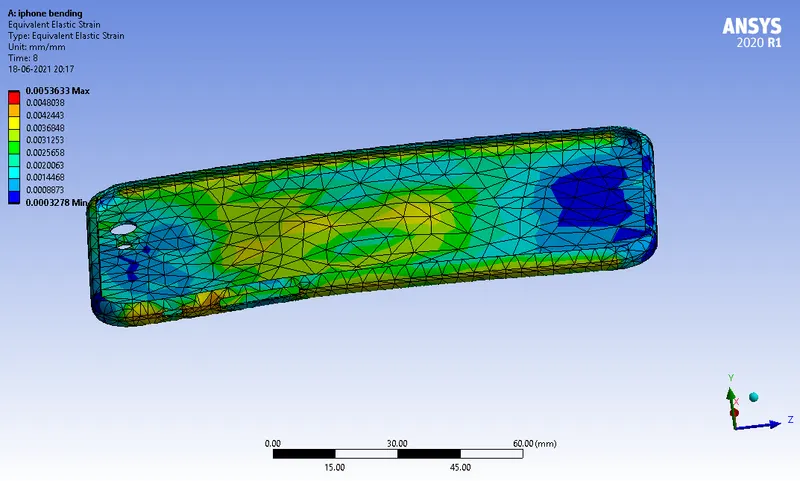
- Equivalent Elastic Strain of the Frame:
- Directional deformation for the Frame:
CONCLUSION:
From the results, it can be inferred that
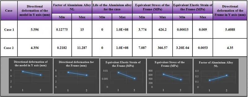
- Directional Deformation of both the model and the frame decreases in Case 2 because bending is done near the Centre of the object (ie near to Centre of Gravity)
- Equivalent Stress and Equivalent Strain also decreases in Case 2 as bending is done near to the Centre of the object.
- Factor of Safety is less than 1 in both the cases which implies that the Working stress or Actual stress is greater than the Yield strength of Al Alloy NL which implies that the product will fail while bending
- However, Factor of safety increased in case 2 as Equivalent stress induced is less in Case 2
- The Fatigue life of the Frame are tabulated above.
The simulation files are attached below