Rolling operation
AIM:
- To perform rolling analysis of copper work piece and obtain the desired output results.
OBJECTIVES OF THE PROJECT:
- To increase the length of the work piece and reduce the width in space claim.
- To add copper alloy NL material to the engineering data.
- To insert the contacts for the wheel and the work piece.
- To insert the work piece movement between the rollers.
- To insert the rotation for the wheels.
- To mesh the rollers and the work piece.
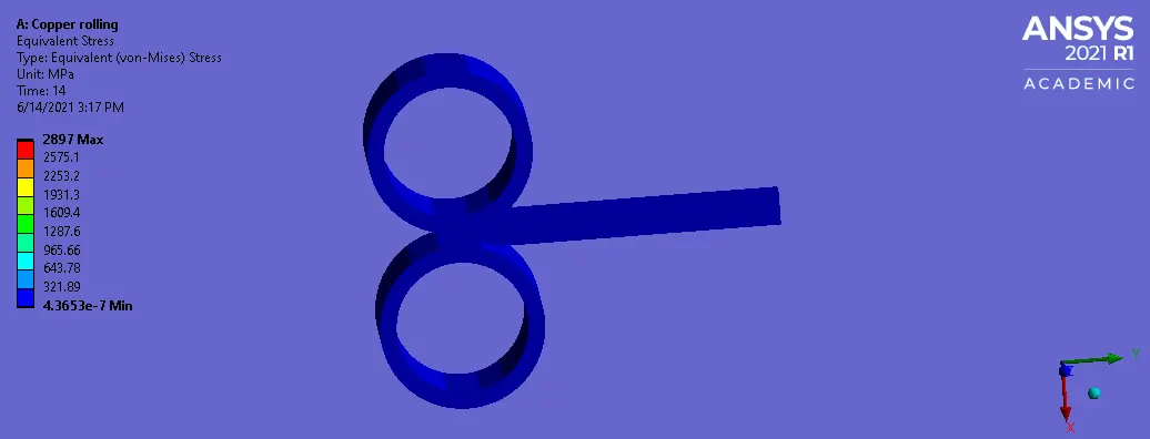
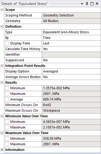
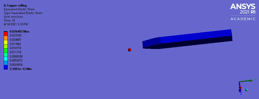
- To evaluate the stress and deformation in the work piece.
PROCEDURE:
- OPEN WORKBENCH21 > NEW PROJECT > STATIC STRUCTURAL.
- This will start a new static structural project.
- Rename the project as Rolling copper.
- Go to ENGINEERING DATA > EDIT > GENERAL MATERIALS NL > COPPER ALLOY NL > ADD.
- This will add the copper alloy NL to the material data.
- Then double click on Geometry. This will open the Spaceclaim.
- In Space claim use Pull option to extend the work piece length by 60mm and decrease its both sides by 8mm.
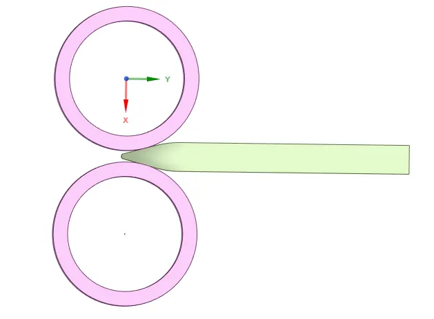
- The geometry for the case is done and exit the Spaceclaim.
- Then double click on Model. This will open Mechanical module.
- Now, rename the geometry as roll1, roll2 and work piece.
- Then assign copper alloy NL to work piece.
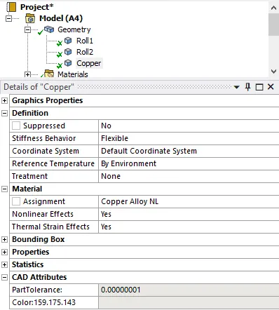
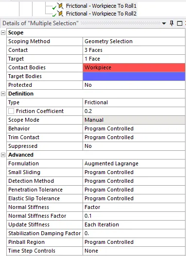
- Then go to CONTACTS > FLIP > RENAME BASED ON DEFINITION.
- Define the contact faces correctly for both the contacts.
- Select both the contacts and define TYPE = FRICTIONAL > FRICTIONAL COEFFICIENT = 0.2 > FORMULATION = AUGMENTED LAGRANGE > NORMAL STIFFNESS = FACTOR > 0.1 > UPDATE STIFNESS = EACH ITERATION > INTERFACE TREATMENT = ADD OFFSET, RAMPED EFFECTS.
- INSERT > JOINTS > BODY-GROUND > TYPE = CYLINDRICAL > SCOPE > INNER FACE OF ROLLER.
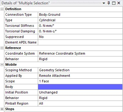
- Similarly, define cylindrical joint for roller 2.
- Now, go to MESH > INSERT > SIZING > SCOPE = WORK PIECE > ELEMENT SIZE = 2MM > GENERATE MESH.
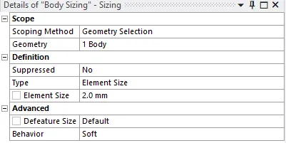
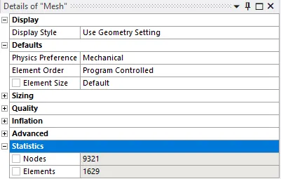
- The mesh will be generated on the model.
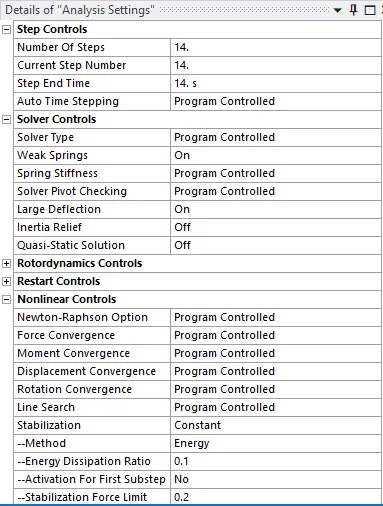
- Then go to STATIC STRUCTURAL > ANALYIS SETTINGS > NO OF STEPS = 14 > LARGE DEFLECTION = ON > STABILIZATION = CONSTANT > ENERGY DISSIPATION RATIO = 0.1.
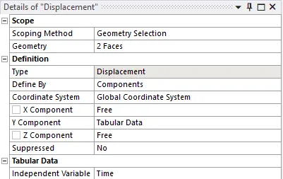
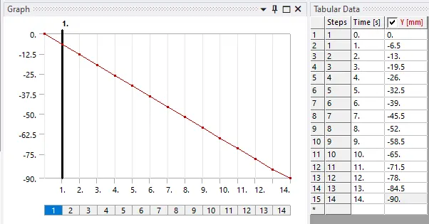
- Go to STATIC STRUCTURAL > INSERT > DISPLACEMENT > DEFINE BY = COMPONENTS > GEOMETRY > WORK PIECE > MAGNITUDE = Y TABULAR and insert the following values.
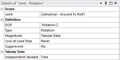
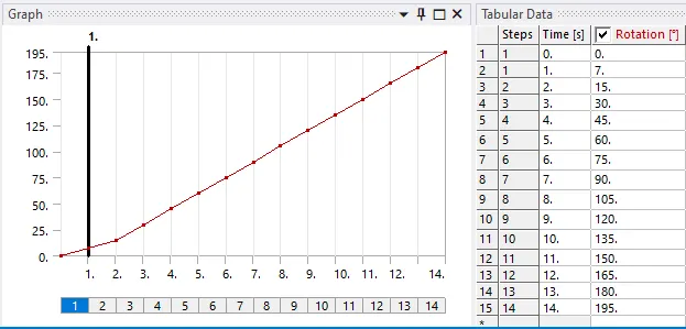
- Then, go to SOLUTION > INSERT > JOINT LOAD > JOINT = CYLINDRICAL GROUND TO ROLL1 > TYPE = ROTATION > DOF = Z > MAGNITUDE = TABULAR DATA.
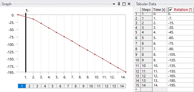
- Similarly, define rotation for the Roll2.
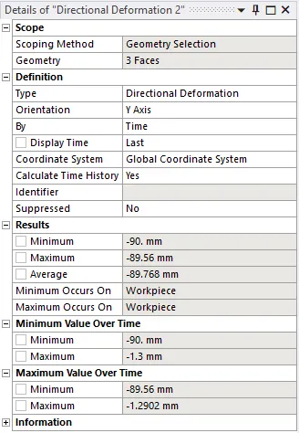
- Then, go to SOLUTION > INSERT > STRESS > STRAIN > DEFORMATION.
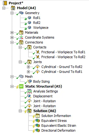
- This will set the output results.
RESULTS:
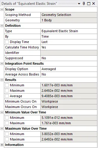
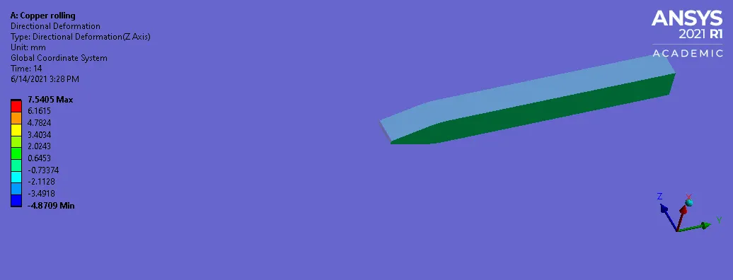
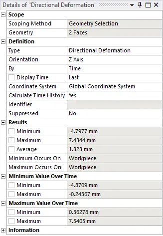
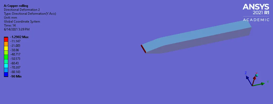
LEARNING OUTCOMES:
- To add copper alloy NL material.
- To edit Geometry in Spaceclaim.
- To assign material from the material library.
- To define frictional roller contacts.
- To define cylindrical joints.
- To deploy mesh on the geometry.
- To define body sizing.
- To define displacement for the work piece.
- To define rotation for rollers.
- To define output results.
CONCLUSION:
- By performing this project we conclude that, the static analysis on the rolling copper workpiece is performed and edge of the workpiece is displaced by 90mm.