Week 4- Rolling operation
-
Objective: To simulate the rolling operation on a workpiece made of copper.
-
Procedure: Open the static structural analysis system in the Project schematic. Rename it to copper sheet rolling. The material used for analysis is Copper Alloy (NL). The material is added to the material
library in Engineering Data. Now proceed to import the Geometry. Import the Geometry. As per the given conditions, we have to increase the length of workpiece by 60mm and reduce the sides by 8mm
each. Open the Geometry in SpaceClaim. This is done by using Pull option. The geometry initially and after updating is shown below.
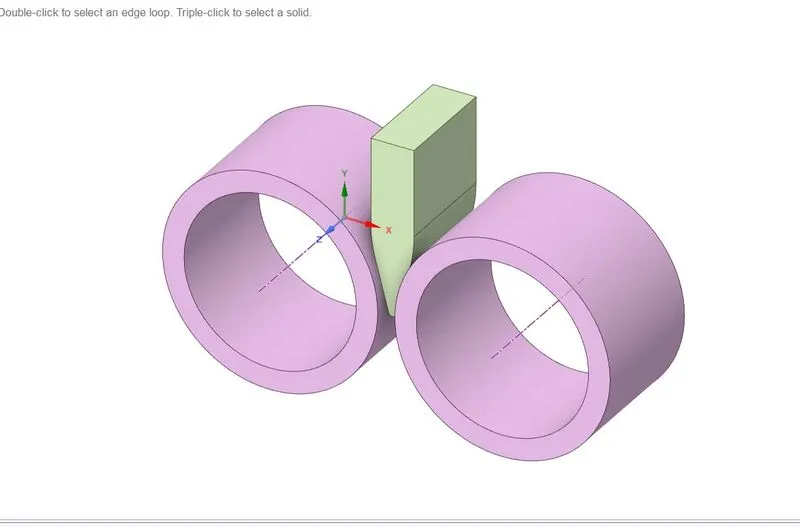
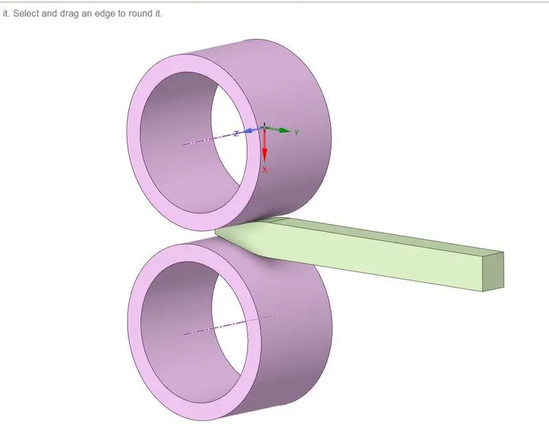
Close the SpaceClaim and update the Model in the Project Schematic and open Mechanical Module. Update the material of the workpiece to Copper alloy NL. The Ansys automatic contact detection has
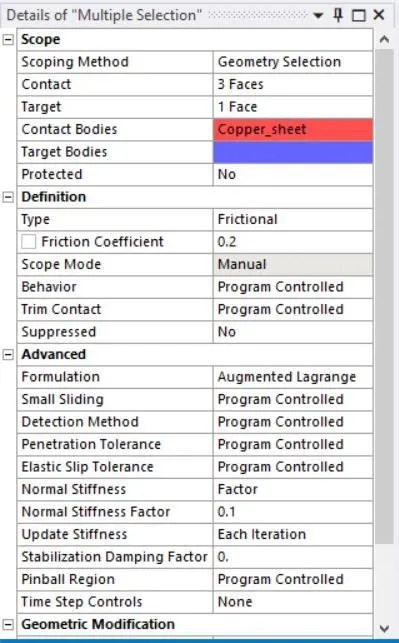
detected some initial contact between the rollers and the workpiece. The contact between the rollers and the workpiece is updated with target body as rollers and the contact body as workpiece. Frictional
type contact is used with coefficient of friction as 0.2. Following contact settings is defined.
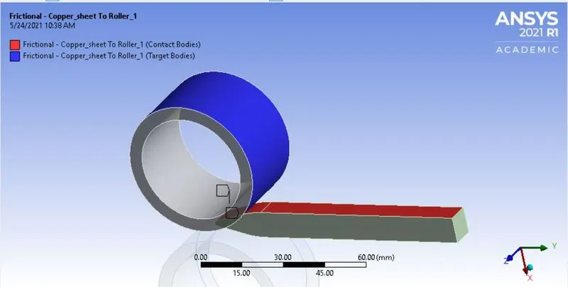
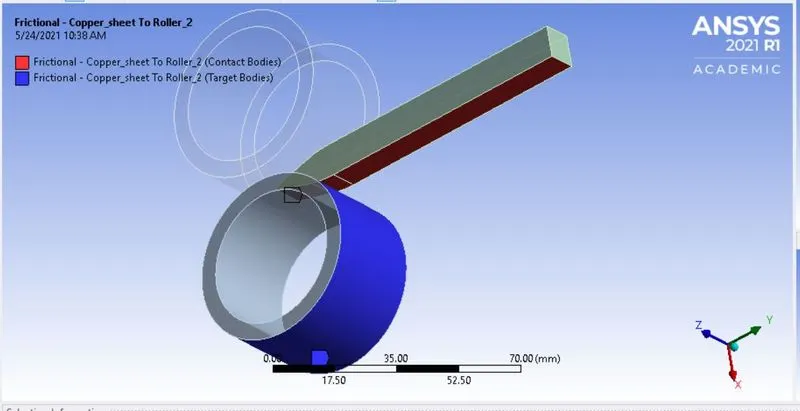
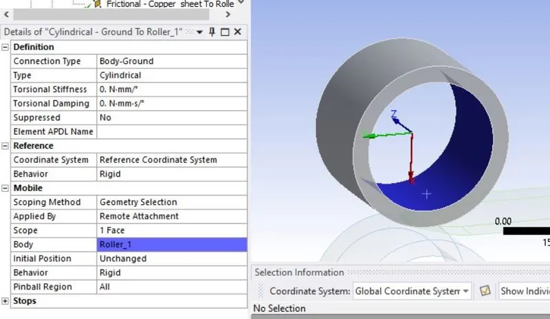
The rollers will be rotating and therefore acts act as cylindrical joints. Go to Connections > Insert > Joints. Set Connection type to Body Ground and type as Cylindrical. For geometry selection, select the
inner surface of the roller.
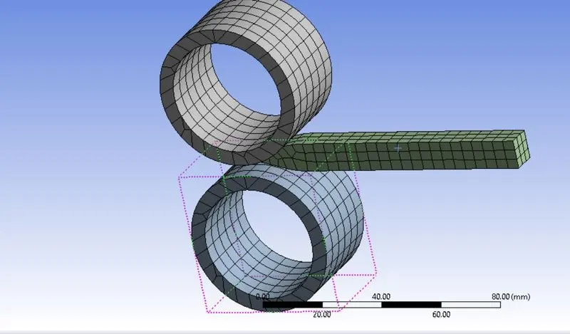
Similarly, define cylindrical joint for the other roller. For meshing, default mesh for the rollers is accepted. The mesh in the workpiece is refined by using sizing of 4 mm on the workpiece.
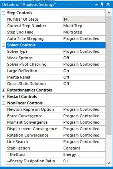
We have to run the simulation for 14 steps and the edge of the workpiece is to be displaced by 90mm as per the given condition. In the Analysis settings, set the no. of steps = 14. Large deflection is turned
on, since the problem is non linear. Following settings is used for the steps:
Now insert the Displacement load for the copper sheet. Go to Static Structural > Insert > Displacement. The sides of the workpiece are selected in order to apply displacement and avoid slipage of the
workplace. The displacement values are provided in steps in tabular format as shown below:
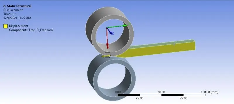
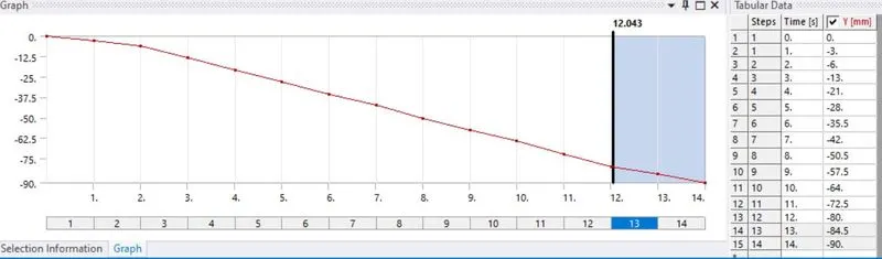
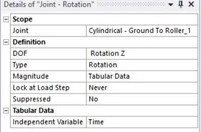
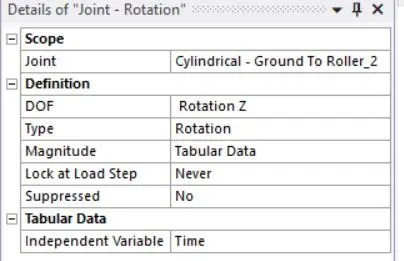
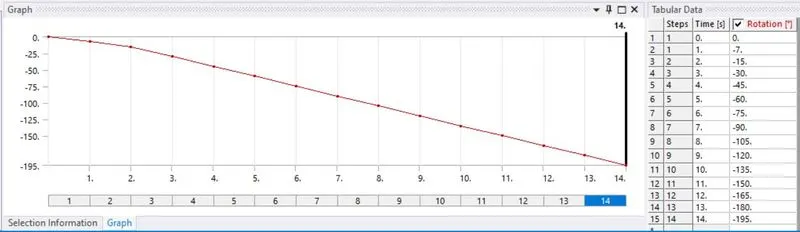
Define the joint load for the roller joint. The upper gear will rotate in clockwise direction. Go to Static Structural > Insert > Joint Load. Select the Cylindrical joint for the Roller_1. Select DOF as Z rotation and
type as Rotation. For magnitude, enter the value of rotation in tabular format as shown below.
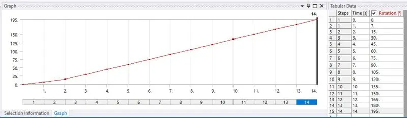
Similarly, define joint load for the other roller. This roller will rotate in anticlockwise direction.
Case setup is now complete. Request output fo Equivalent stress, Equivalent Plastic strain for the workpiece and Directional Deformation in the Z axis for the workpiece. Now run the simulation.
- Results:
- Stress contour:
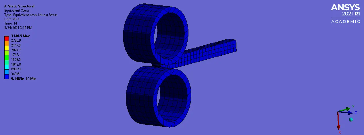
Max stress of 3146.5 Mpa is observed on the copper sheet.
2. Equivalent Plastic strain for the workpiece:
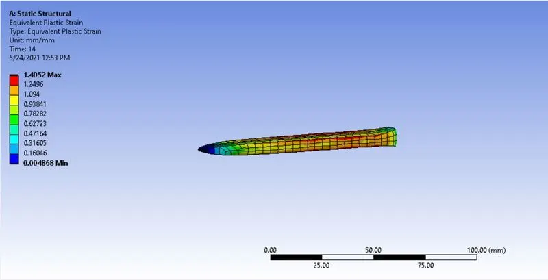
Equivalent Plastic strain of 1.40 for the workpiece is observed.
3. Directional Deformation in the Z axis for the workpiece:
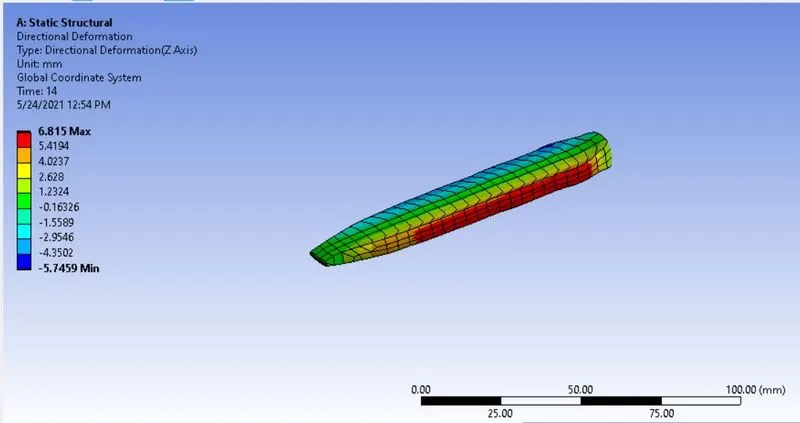
Deformation of 6.8 mm is observed in the Z direction.
Also, we have to prove that the workpiece has been displaced by 90mm. For that, insert Directional Deformation with orientation for Y axis. In the geometry selecter, select the 2 displayed faces of the free
end of the workpiece and then evaluate the results.
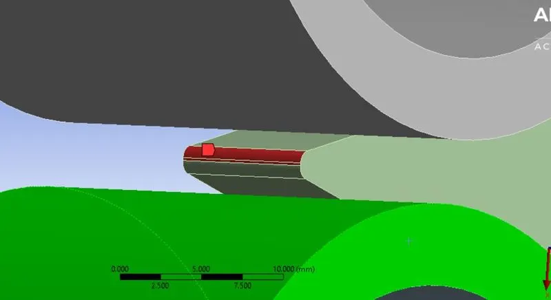
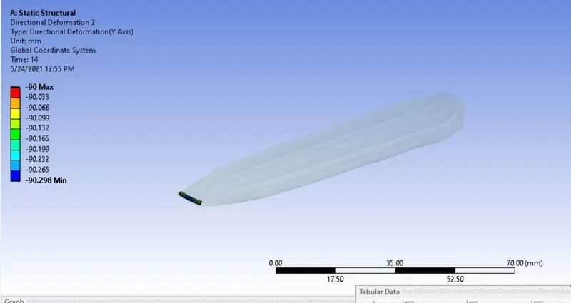
As seen above, maximum deformation of -90 mm is observed, which is the same as maximum displacement inputted for the workpiece. Thus, it is verified that the workpiece has been displaced by 90 mm.
- Conclusion: Thus, the analysis for the copper sheet rolling has been successfully completed and the requested results are also obtained.