Week 4- Rolling operation
OBJECTIVE:-
To run the simulation for a work-piece made of copper. Initially its length has to be increased by 60 mm and its thickness has to be decreased by 8 mm on both sides.
PROCEDURE FOLLOWED:-
Create a new static structural, and add a new material from engineering data, copper alloy from general non linear materials. Check for properties and proceed.
Import the geometry provided, Edit the geometry in Space claim. Editing to be made is increase length of the specimen by 60 mm and decrease the thickness of the specimen by 8 mm on both sides.
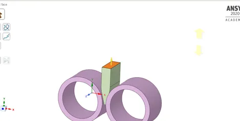
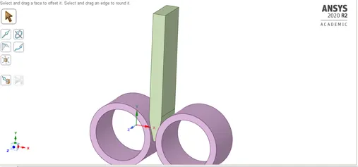
Also decreasing its thickness by 8 mm on both the sides.
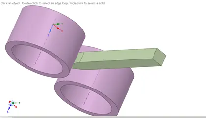
Post edit in space-claim we will be proceeding with the edit geometry in the mechanical workbench.
At first renaming the geometry name and then assigning the material as [per the requirement,Structural steel to both the rollers and copper alloy NL to the specimen.
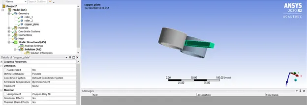
Now making changes to contact as per the requirement, as we can see that the contact are not proper in between the roller and the specimen.
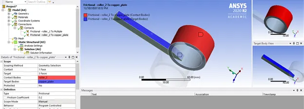
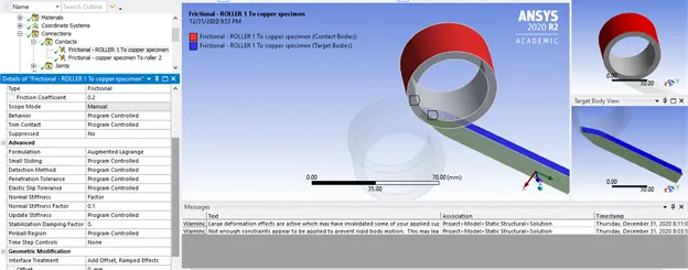
Also there are some changes to be made in the parameters of this conatcts
Type = frictional
Firctional coefficient = 0.2
Formulation = Augmented lagrange
Normal stiffnes factor = 0.1
Interface treatment = add offset, ramped effects.
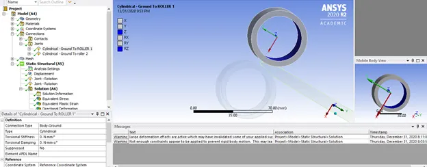
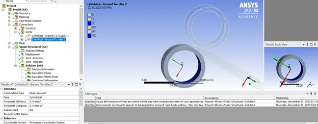
Now we have to define joints for the rollers
Now Mesh = default mesh size to be assigned
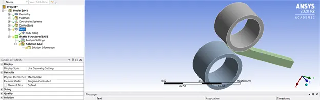
add Sizing for copper specimen = 4 mm mesh size
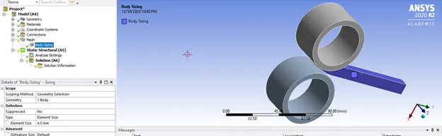
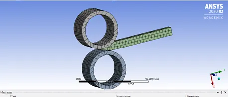
Generating mesh
Analysis setting has to be done for proper simulation.
Steps = 14
Select multi steps and assign the following:-
Large deflection = ON
Stabilization = Constant
Energy dissipation factor = 0.1

After the analysis setting has been done, Its time for inserting displacement for specimen,
Insert – displacement – select both sides of the specimen.
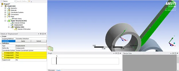
Since the displacement load has to be defined in the negative y-direction. In our case we have to displace the specimen by 90 mm thus assigning the values so that it can be displaced.
Giving the tabular data in the negative Y- direction,
The data entered are as follows:-
|
Steps |
Displacement |
|
0. |
0. |
|
1. |
-3. |
|
2. |
-7. |
|
3. |
-14. |
|
4. |
-21. |
|
5. |
-28. |
|
6. |
-35. |
|
7. |
-42. |
|
8. |
-49. |
|
9. |
-56. |
|
10. |
-63. |
|
11. |
-70. |
|
12. |
-77. |
|
13. |
-84. |
|
14. |
-91. |
After the displacement the joint load has to be entered for both the rollers, the data tabulated are as follows:-
|
Steps |
Angular rotation |
|
0. |
0. |
|
1. |
7.5 |
|
2. |
15. |
|
3. |
30. |
|
4. |
45. |
|
5. |
60. |
|
6. |
75. |
|
7. |
90. |
|
8. |
105. |
|
9. |
120. |
|
10. |
135. |
|
11. |
150. |
|
12. |
165. |
|
13. |
180. |
|
14. |
195. |
Inserting the solution requirement for the Von-mises stress for the geometry, Equivalent plastic strain for the copper specimen, directional deformation for the copper specimen. Also to know whether the specimen has travelled to a distance of 90 mm adding other directional deformation along y axis.
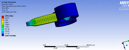
Von-mises stress
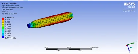
Plastic strain in the specimen
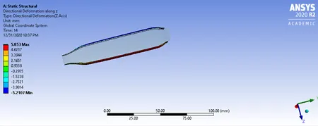
Directional deformation of the specimen along Z-axis
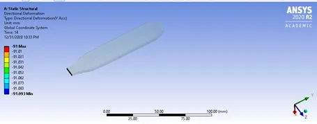
Directional deformation of the specimen along the Y-axis.
CONCLUSION:-
The simulation is run for copper non linear specimen rolling operation, and the results are tabulated.
The results are as follows:-
Directional deformation(Z-axis) = 5.853 mm
Von-mises stress = 2495.6 MPa
Equivalent plastic strain = 1.3592 mm/mm
Directional deformation(Y-axis) = -91 mm(hence proved) that the specimen had travelled a distance of 91 mm.