Week 4- Rolling operation
Aim: To simulate the rolling operation on the workpiece made up of Copper and Equivalent stress,Equivalent plastic strain in the workpiece and directional deformationi in the workpiece.
Procedure:
select the statis structural model in ANSYS workbench .
Select the material in engineering tab
select material copper Alloy NL, in general non linear material,
The mechanical properties of Copper alloy NL material is given below
Density: 8300 kg/m³
Young's Modulus: 1.1e+05
Poisson's Ratio: 0.34
Bulk Modulus: 1.1458e+05 MPa
Shear Modulus: 41045 MPa
Specific Heat Constant Pressure: 3.85e+05 mJ/kg·°C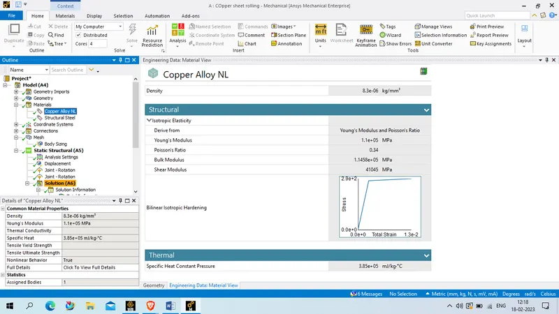
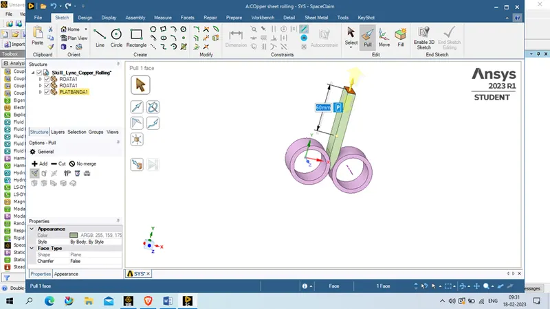
Import geometry and open in spaceclaim in ANSYS workbench
after that pull the workpiece length to upwork direction to 60 mm
Decrease the width of workpiece to 8 mm in z direction ,
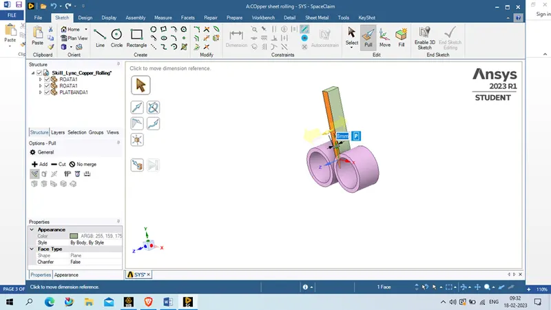
repeat the same 8 mm decreasse the width of workpiece in opposite face
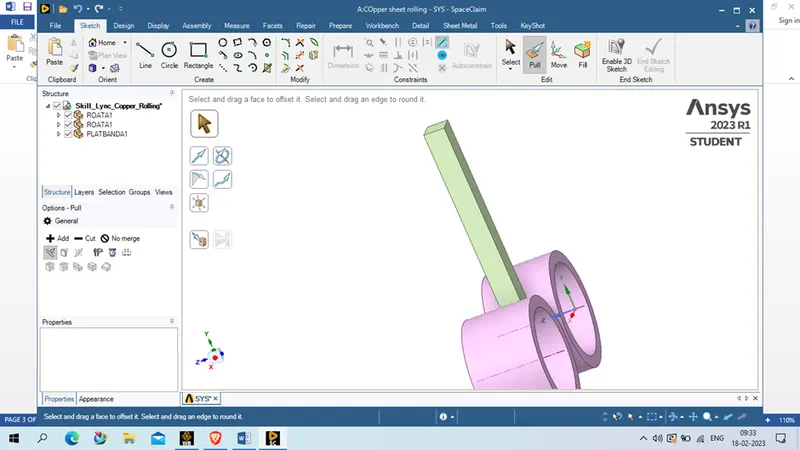
now exit from spaceclaim and update the geometry in model in static structural model, and open it using edit option
Now expand the geometry tab and rename as per convenient, in this case both roller we named as wheel1 and wheel 2 and workpiece
Also assign the workpiece material as Copper alloy NL, and both wheel and structural steel
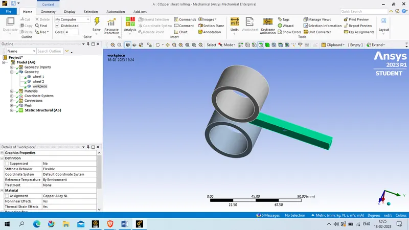
now expand connection tab and flip the connection so that contact will be workpiece and target will be wheel 1 and wheel 2 , rename that base on connection.
select all connectiong faces like all wheel outer face as target and respective workpiece face
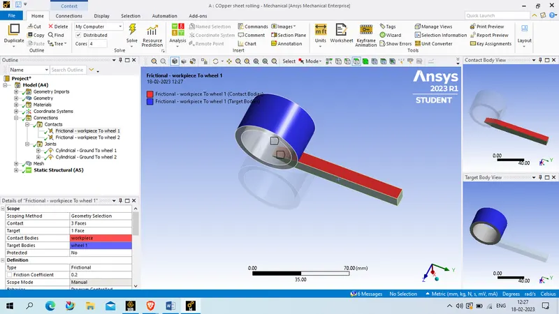
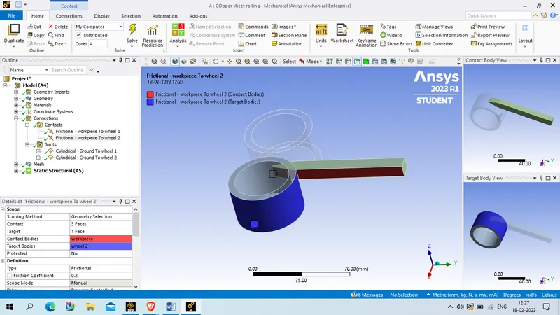
Now assign the conection as frictional and co efficient of friction as 0.2.
fromulation _ augmented lagrage
normal stiffness- factor
normal stiffness factor - 0.1
update stiffness- each ittration
interface treatment - add offset, ramped effect
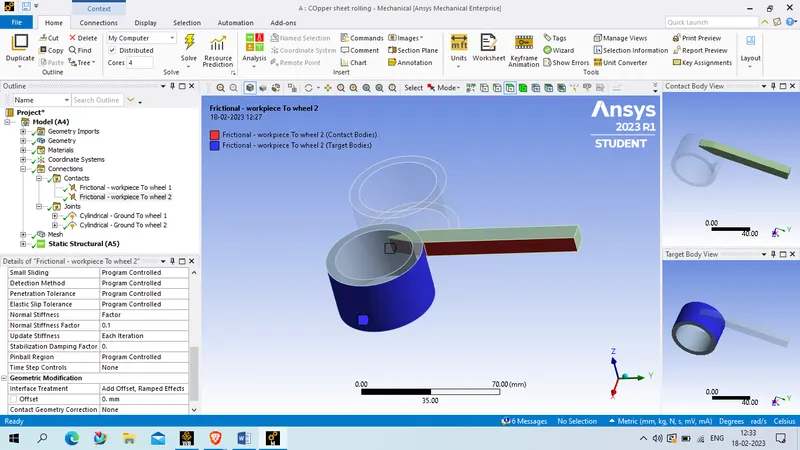
NOw delpoy a cylindrical joint to both wheel as below
connection type - Body-ground
Type - cylindrical
rotate abount z axis as per given below , and select the inner face of wheel
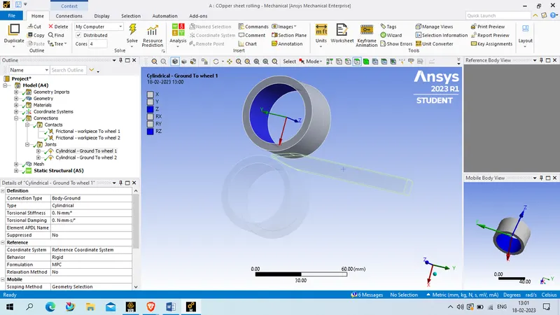
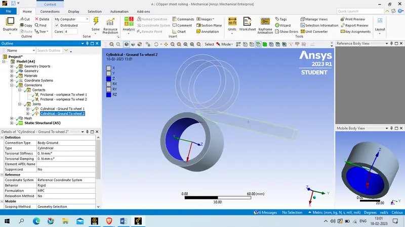
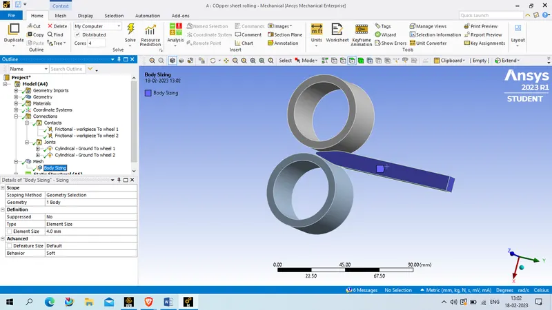
for mesh: we will use defult generatef mesh on wheel , and for workpeice we will provide element size as 4 mm
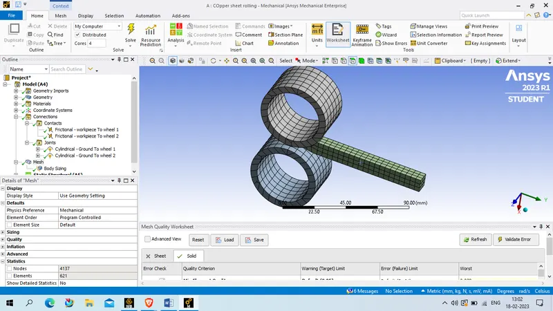
Element quality :
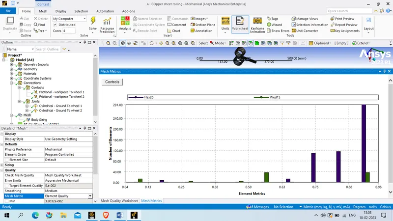
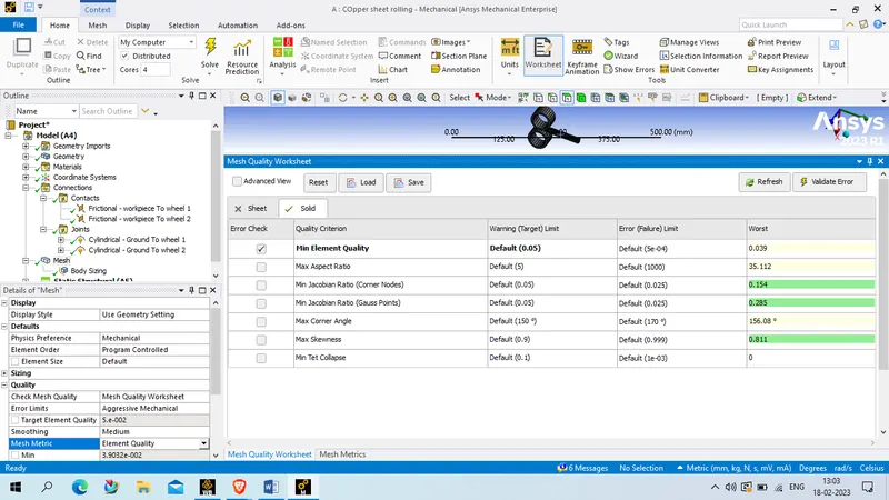
as most of the element have good quality , in range od 0.6 to 1 we will proceed further with this mesh. the statics of the mesh given below
No of node:4137
No od element : 621
Analysis setup:
no of step ; 14
select all step and provide below setting
large deflection: On
Stabilization : constant
energy dissipation ratio: 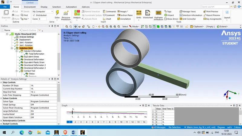
now provide displacement to the workpiece , select 2 face of workpeice and provide load as displacement
Define by: component
y component - tubular data
in tubular data steps as per given below
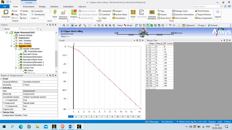
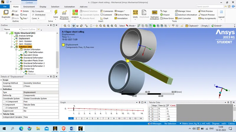
after that we will provide rotational joint to wheel , one wheel in clock wise and 2nd wheel in anticlock wise rotation.
scope : cylindrical- ground to wheel,
DOF:rotation Z
Magnitude : tubular date
Tutular data steps as per given below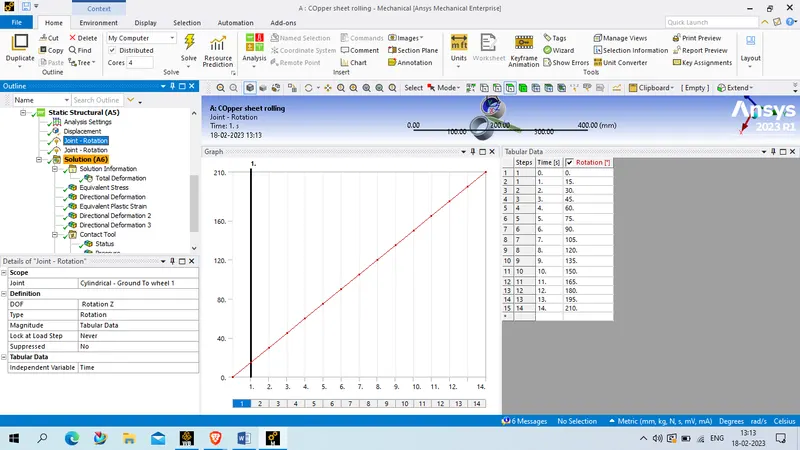
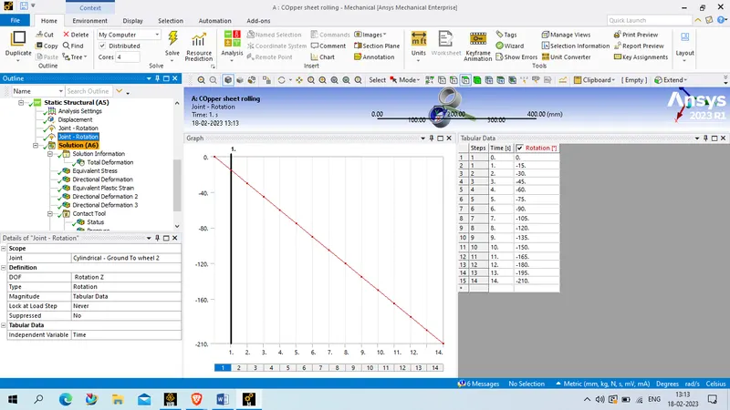
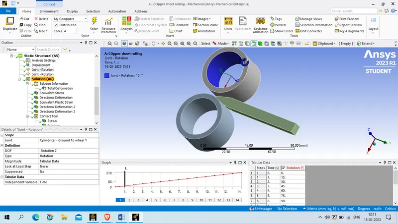
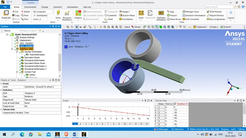
After defining all thing we will solve for
- Equivalent stress for the whole setup
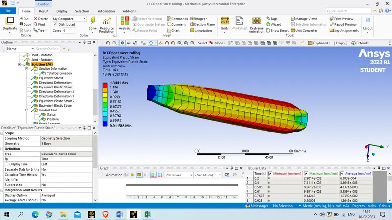
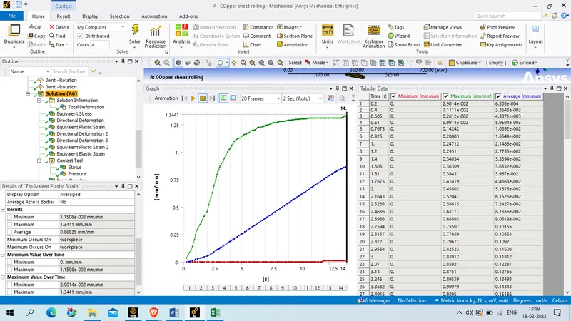
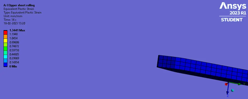
- Equivalent Plastic strain for the workpiece
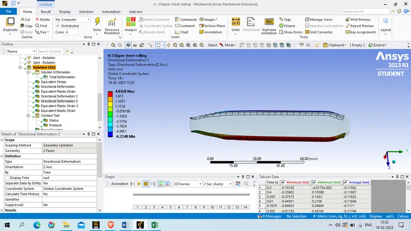
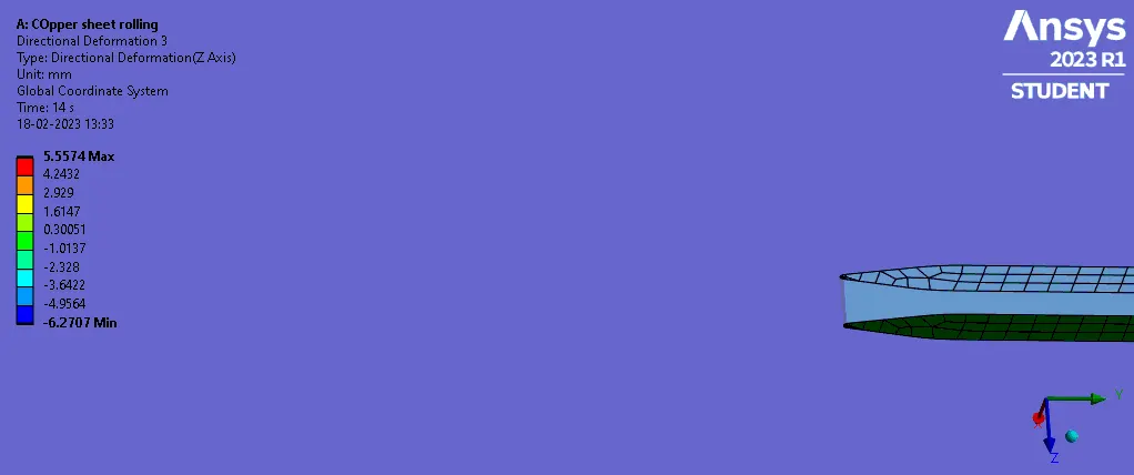
- Directional Deformation in the Z axis for the workpiece
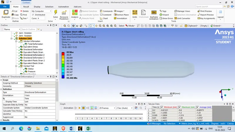
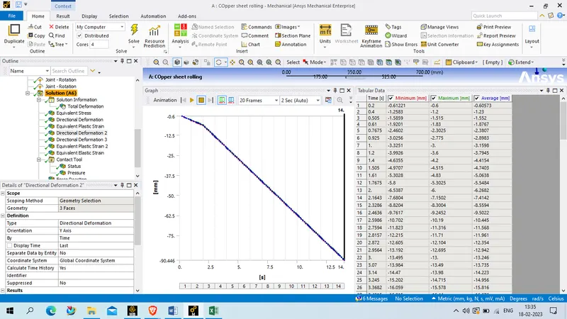
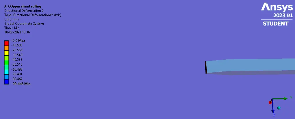
- Prove that the workpiece has displaced by 90mm
Result picture:
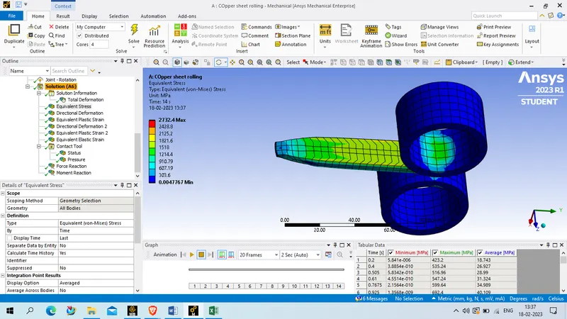
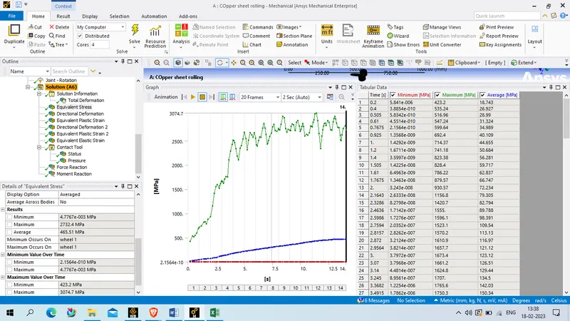
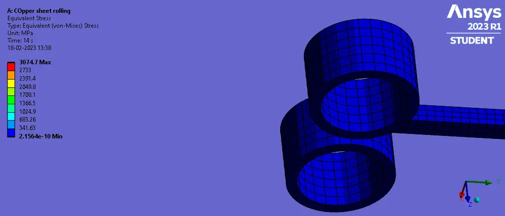
Equivalent stress for whole setup
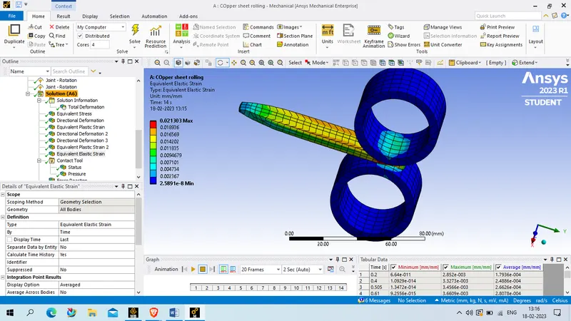
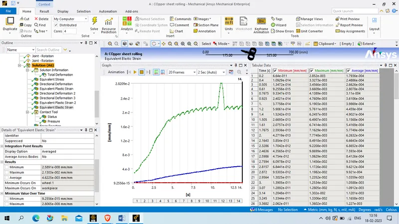
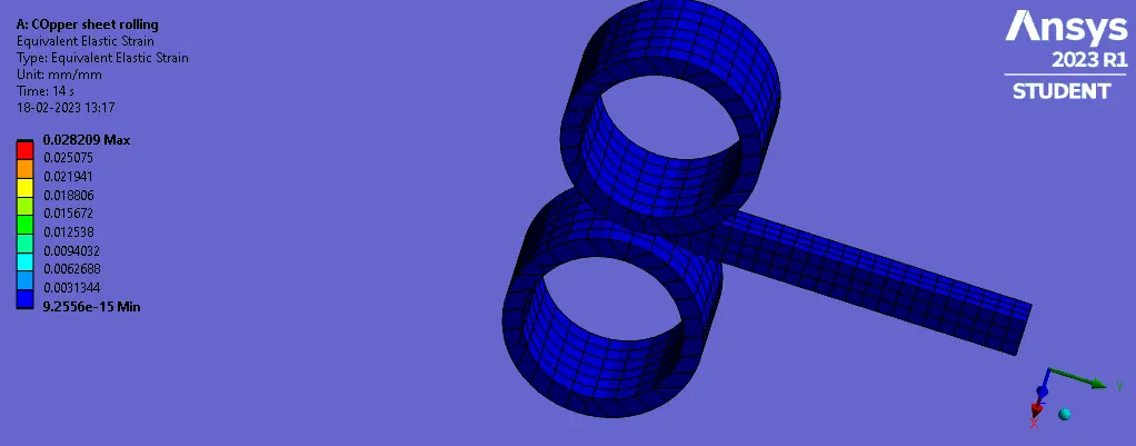
Equivalent Plastic strain for the workpiece
Directional Deformation in the Z axis for the workpiece
Directional deforamtion in Y axis
Equivalent stress on whole setup
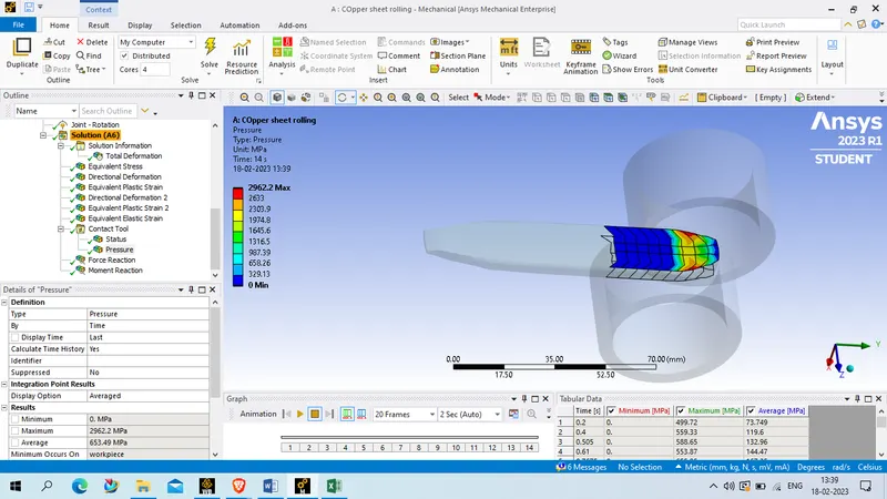
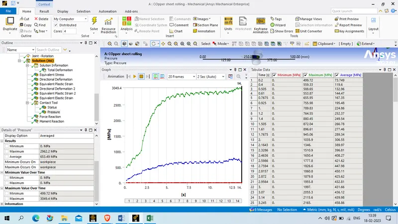
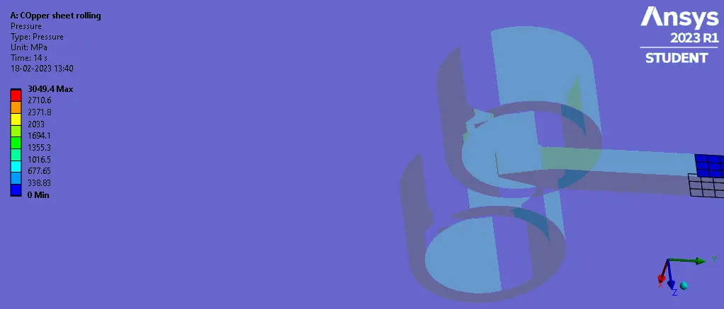
COntact Pressure
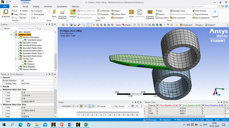
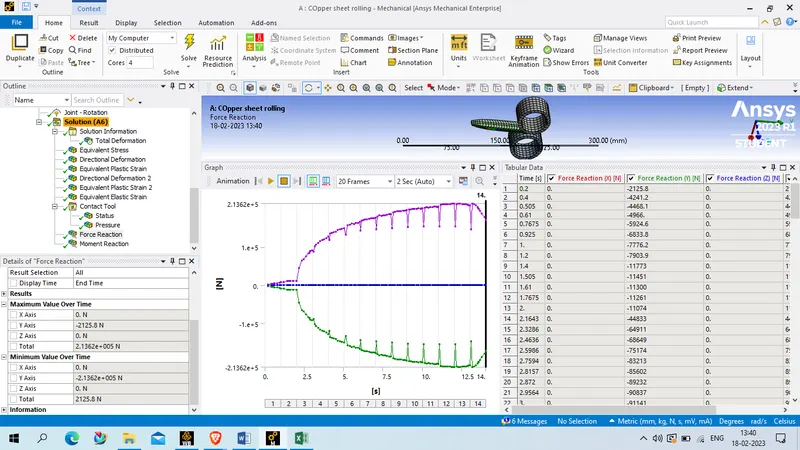
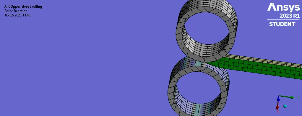
FOrce Reaction
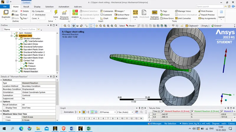
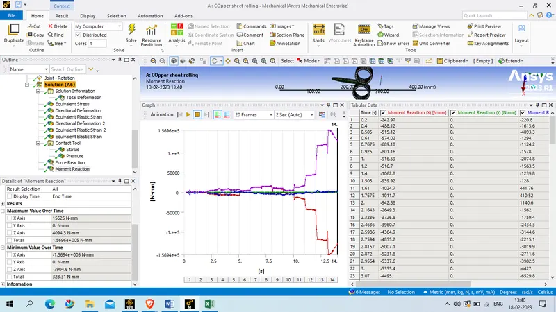
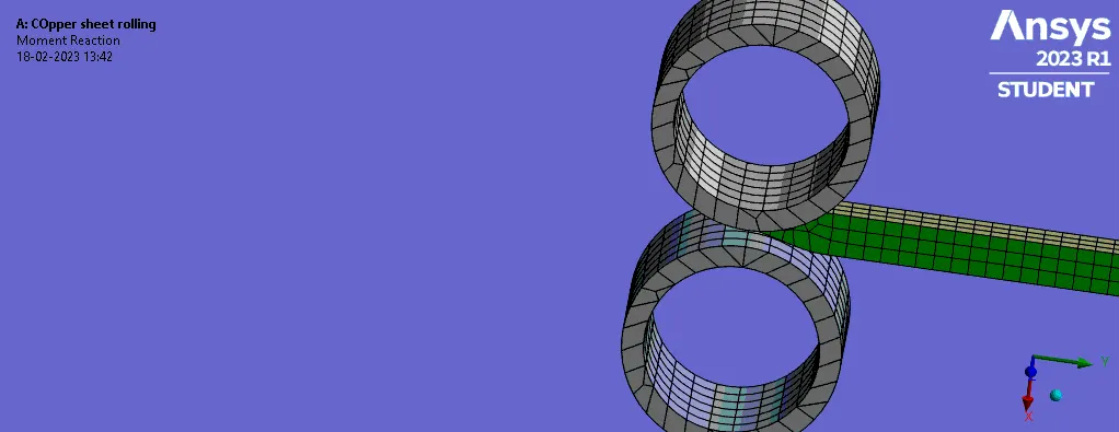
Moment reaction
Result:
The equivalent strain on hile body is given below
| Material | time (s) | Minimum | Maximum | Average |
| Copper Alloy NL | 14 | 2.59E-08 | 2.13E-02 | 4.62E-03 |
The equivalent plastic strain on workpeice is as given below
| Material | time (s) | Minimum | Maximum | Average |
| Copper Alloy NL | 14 | 1.15E-02 | 1.3441 | 0.86835 |
The total directional deformation in z axis is given as below
| Material | time (s) | Minimum (mm) | Maximum(mm) | Average(mm) |
| Copper Alloy NL | 14 | -6.2248 | 4.8428 | -0.6817 |
The Directional deformation in Y axis of workpeice is given as below
| Material | time (s) | Minimum (mm) | Maximum(mm) | Average(mm) |
| Copper Alloy NL | 14 | -90.446 | -90 | -90.222 |
The equivalent stress on whole body is given below
| Material | time (s) | Minimum (MPa) | Maximum(MPa) | Average(MPa) |
| Copper Alloy NL | 14 | 4.78E-03 | 2732.4 | 465.51 |
COntact pressure of the system is given below
| Material | time (s) | Minimum (MPa) | Maximum(MPa) | Average(MPa) |
| Copper Alloy NL | 14 | 0 | 2962.2 | 653.49 |
Force reaction of the system is given velow
| X axis | y axis | Z Axis | Total |
| 0. N | -2125.8 N | 0. N | 2.1362e+005 N |
Moment reaction in ths system is given below
| X axis | y axis | Z Axis | Total |
| 15625 N·mm | 0. N·mm | 4094.3 N·mm | 1.5696e+005 N·mm |
COnclusion: