Week 4- Rolling operation
OBJECTIVE
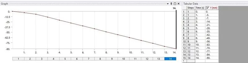
To simulate the rolling operation on a workpiece made of copper . Increase the length of the workpiece by 60mm and decrease its size on both sides by 8mm .Run the simulation for 14 steps and you can give small but random values for the displacement .Ensure that the edge of the workpiece is displaced by 90mm.
FIND THE
- Equivalent stress for the whole setup
- Equivalent plastic strain for the workpiece
- Directional deformation in the z Axis for the workpiece
- Prove that the workpiece has displaced by 90mm
PRODECURE
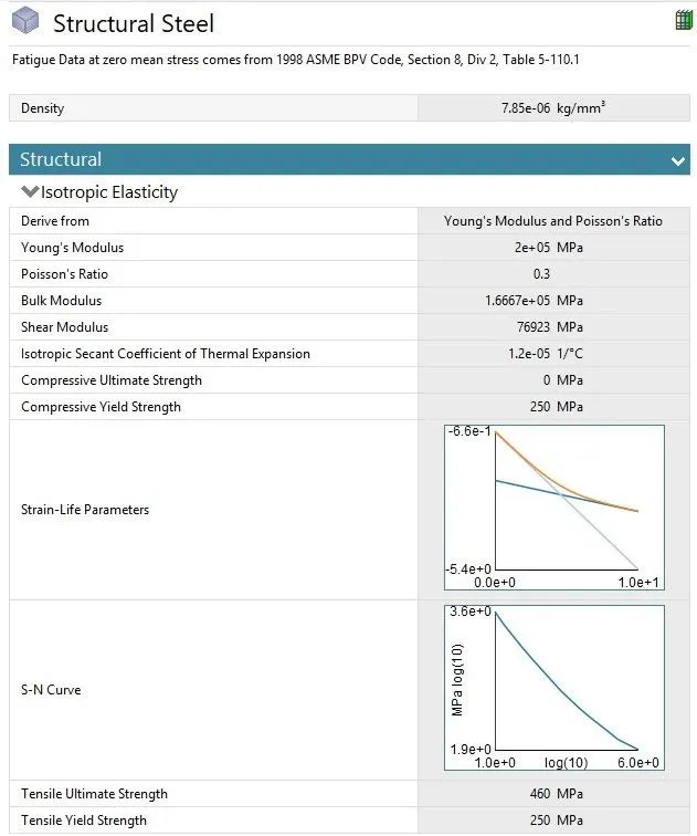
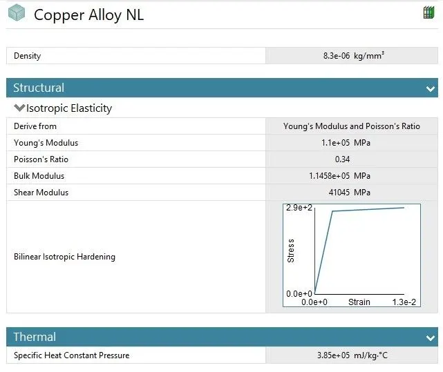
- Create Static structural analysis and in engineering data select the material structural steel and copper alloy.
- Structural steel
- Copper Alloy
- Import the geometry and check in Spaceclaim
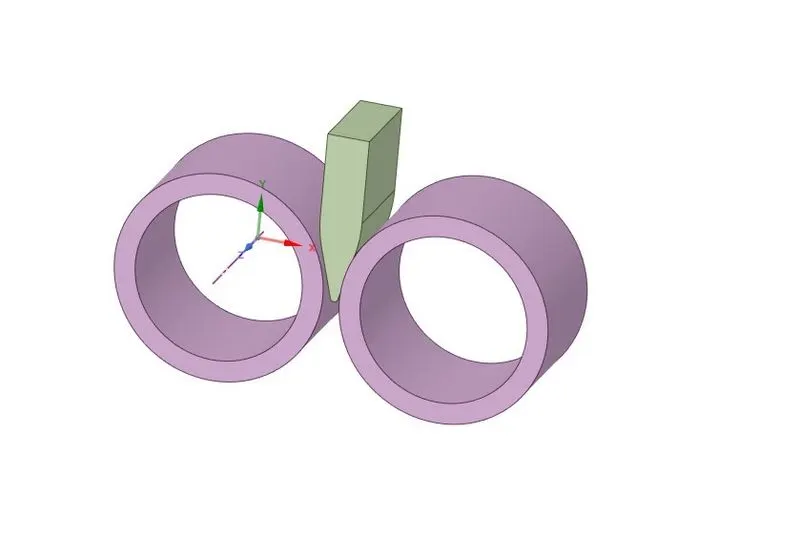
- Performed the following steps
- Increase the length of the workpiece by 60mm
- Decrease its size on both sides by 8mm
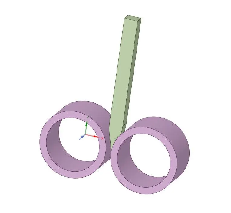
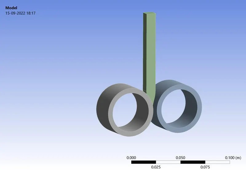
- Then open Ansys Mechanical and rename the geometry as wheel a1 and wheel2 and workpiece then assign the structural steel material to wheel 1 and wheel 2 and copper alloy material to workpiece
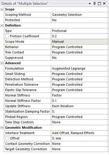
- Contacts There are 2 contacts created in the whole setup with frictional type with friction coefficent of 0.2 formulation is set to augumented lagranage and normal stiffness type as factor and factor value is set to 0.1 .The interface treatment is set to add offset , ramped effects
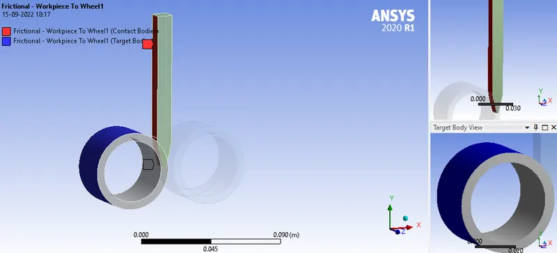
- Contact between Workpiece and wheel 1
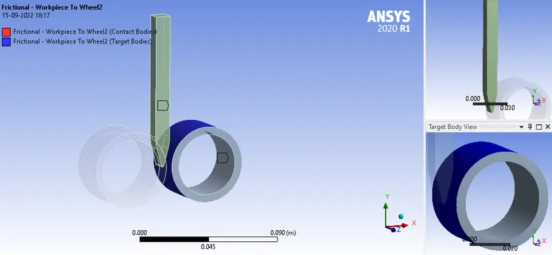
- Contact between workpice and wheel 2
- Joint Both the rolling wheels have a body to ground cylindrical joint
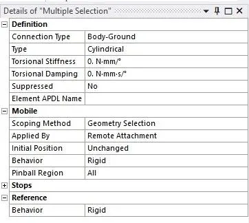
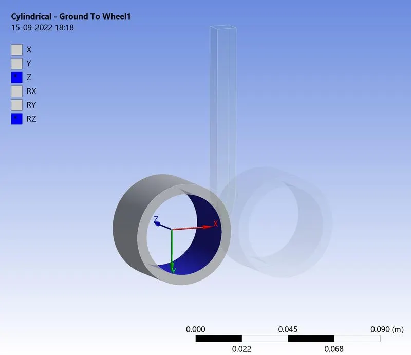
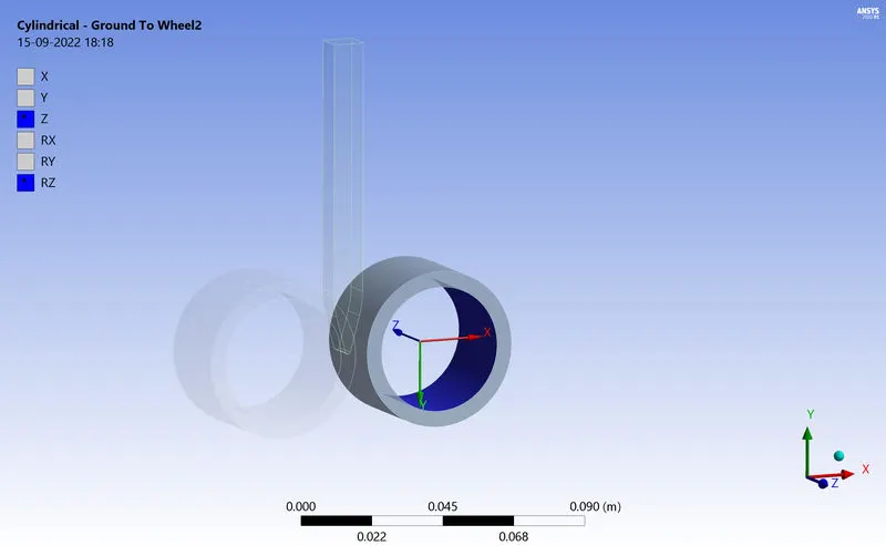
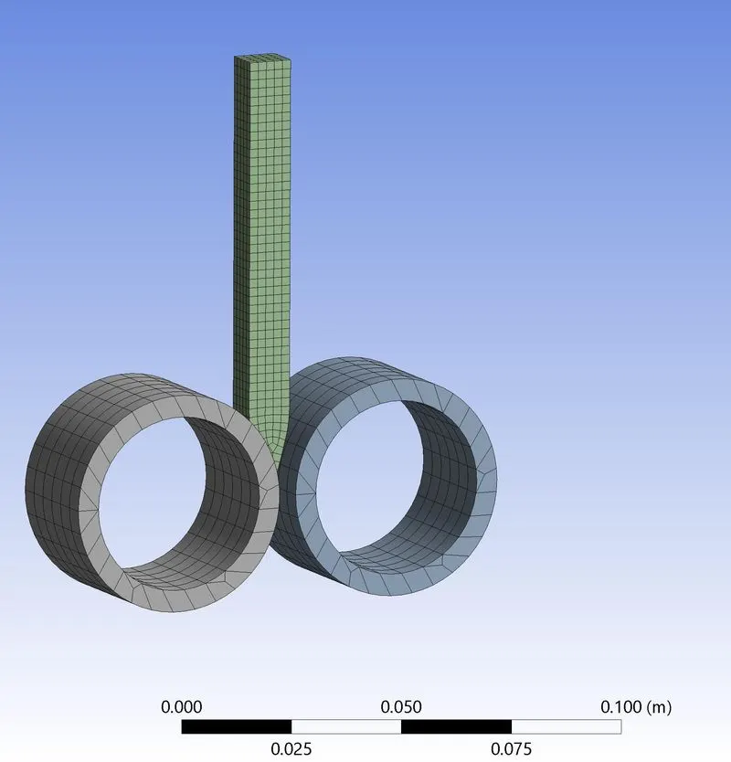
- Mesh Mesh the model using body size option for workpiece with element size of 2mm
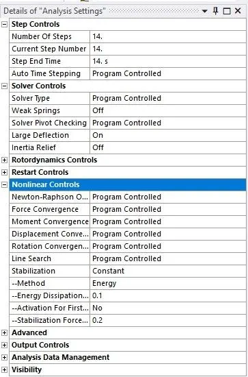
- Analysis Setting The simulation runs for 14 steps . So the number of steps is set as 14 large deflection is set to on and stabilization set to constant method to energy dissipation ratio to 0.1
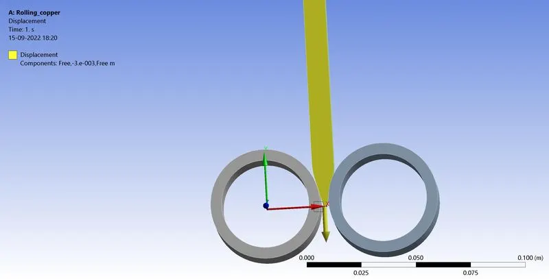
- Displacement The workpiece is provided with a displacement in negative y direction with small increment over the 14 steps
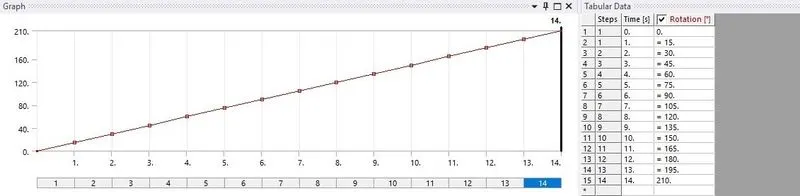
- Joint Rotation The wheel 1 is provider with the rotation on 210 degree
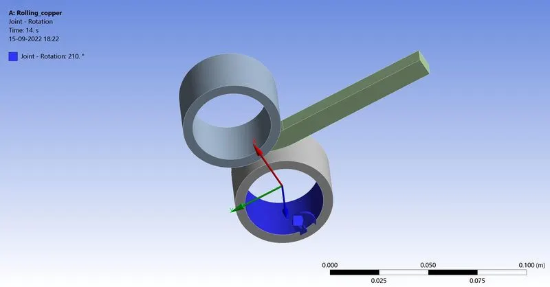
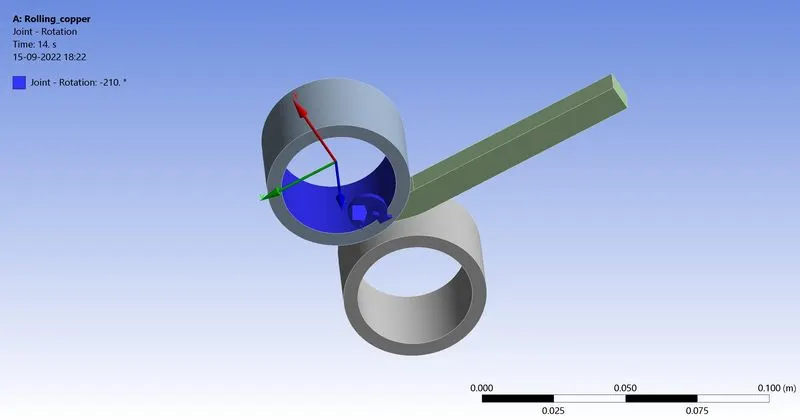
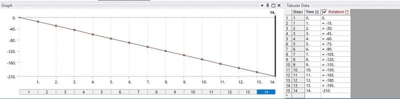
- Joint Rotation The wheel 2 is provider with the rotation on 210 degree
- Run the simulation and results obtained
RESULT The analysis runs successfully and result obtained
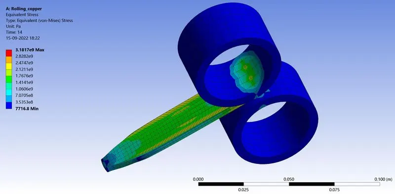
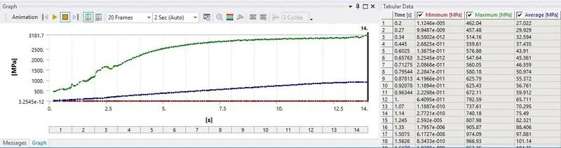
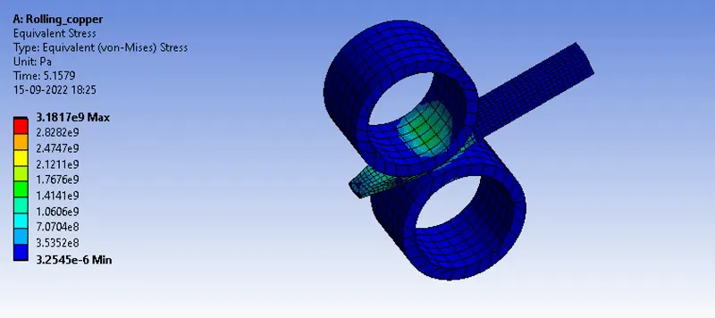
Equivalent stress max - 3181.7 mpa
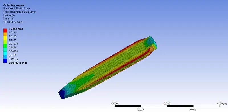
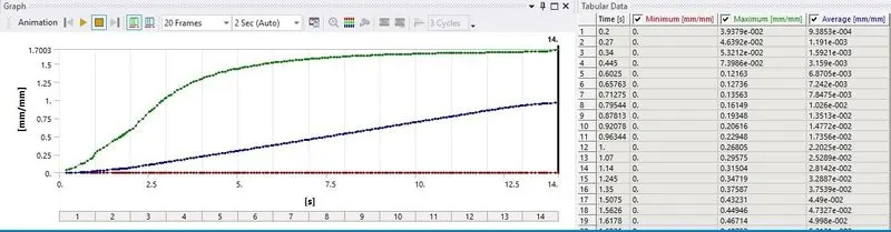
Equivalent Plastic Strain Max - 1.7003 mm/mm
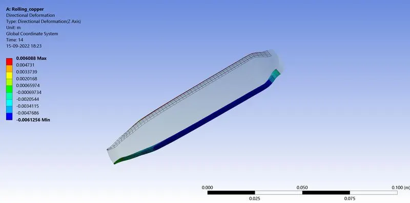
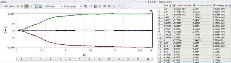
Directional Deformation in the z axis max - 6.088mm
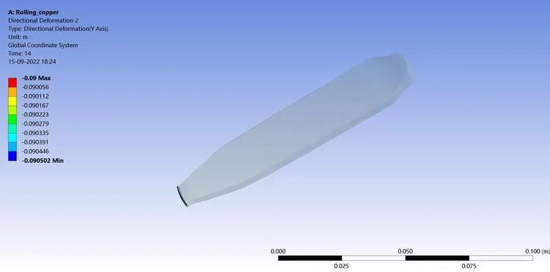
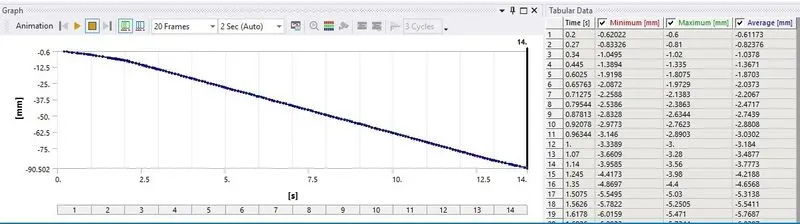
Proof of the workpiece has displaced by 90mm
Equivalent Stress
CONCLUSION
- The maximum stress is experienced on the workpiece at and around the edge that comes in contact with the wheels .The minimum stress is observed on the outer edge of the wheels when they are not in contact with the workpiece .The maximum Equivalent stress is 3181.7Mpa
- The maximum plastic strain is also experienced at the edge of the workpiece in the direction in which they have deformed with a max value of 1.7003
- Directional deformation in the z axis the workpiece deforms by a maximum of 6.088 mm in the z direction
- Proof of the workpiece has displaced by 90mm the directional deformation of the three curved surface on the lower tip of the workpiece shows the displacement of the workpiece by 90mm
LINK : https://drive.google.com/file/d/1MJGeqNm6qQ4tpnZ_62MtvdCbOeK9kHx-/view?usp=sharing