Week 4- Rolling operation
Objective:
- To simulate the rolling operation on a workpiece made of copper under given setup constraints and conditions.
- Chellenge overview:
Increase the length of the workpiece by 60mm and decrease its size on both sides by 8mm. Run the simulation for 14 steps and you can give small but random values( similar to the ones mentioned in the video) for the displacement. Ensure that the edge of the workpiece is displaced by 90mm.
Find out the
- Equivalent stress for the whole setup
- Equivalent Plastic strain for the workpiece
- Directional Deformation in the Z axis for the workpiece
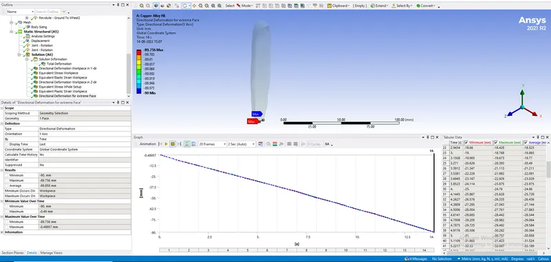
- Prove that the workpiece has displaced by 90mm.
Procedure:
Step 1: Engineering Data
- Add Copper NL material to drop down list of materials.
Step 2: Geometry
- Right click on geometry and Import the Skill_Lync_Copper_Rolling.stp extension file
- Rename the Static Structural tab as Copper Sheet rolling.
- Update the Static Structural tab and proceed to edit geometry in spaceclaim.
- Extend its length by 60mm.
- Reduce side face extrusion by 8mm on both sides.
- update the Model tab and open click Edit.
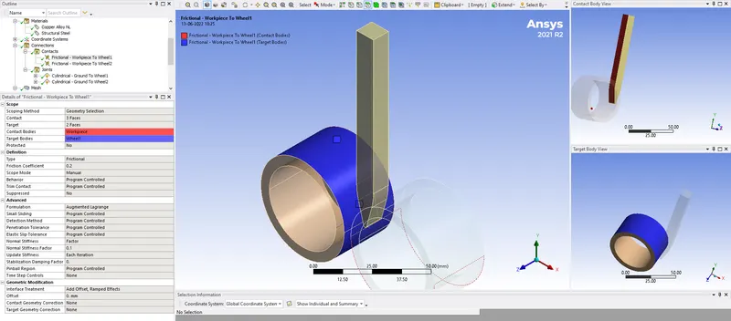
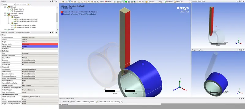
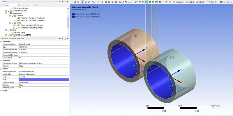
Step 3: Model and Meshing
- Open Model and under geometry assign names according to convenience for better understanding.
- Rename geometries as Wheel 1, Wheel 2 and workpiece.
- Assign Copper NL material to Workpiece
Step 4: Connections
- Contacts:- Define the contact faces between wheel and workpiece properly. Change type of contact to frictional in both cases.
- Change frictional coefficient to 0.2 using Augmented Lagrange as Formulation method
- Define Normal Stiffness using Factor value of 0.1, and change interface treatment to Add offset, Ramped effects. Update stifness to each iteration.
Step 5: Setup
- In analysis settings we are going to simulate this case in 14 steps.
- Select all steps and switch on the large deflection in solver controls.
- From Non Linear controls change stabilization to constant with energy dissipation ratio as 0.1
- Insert Displacement to workpiece along Y direction defined by tabular data. (carefully select both side faces to avoid slipping).
- Insert Joint load as rotational type defined by tabular data with angular increments of 15 deg, first excepetion being 7 deg, 15, 30 and so on.
- Similarly Insert Joint load as rotational type defined by tabular data with angular increments of -15 deg, first excepetion being 7 deg, 15, 30 and so on for second wheel.
**In Case cylindrical joint deosnt work try using revolute body-ground fized joint to avoid unnecessary movemnt of wheels in Z direction.
Results and Conclusion:

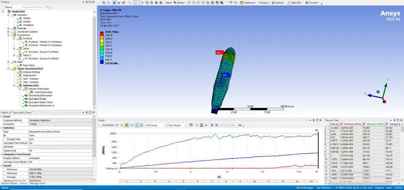
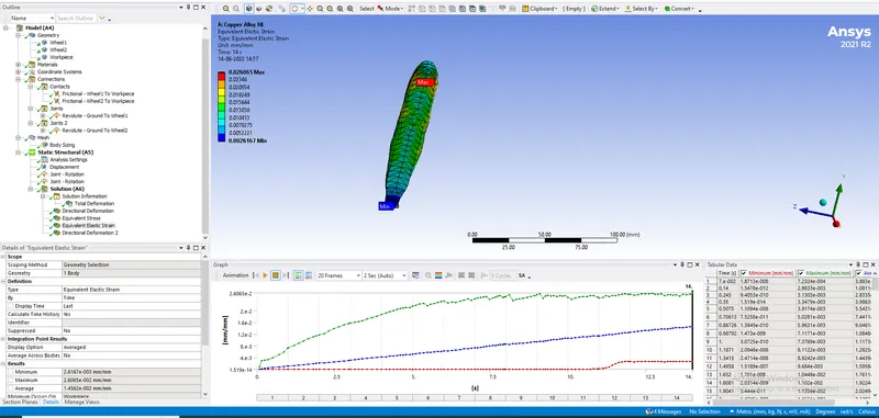
Result data:
|
Equivalent stress for the whole setup |
Equivalent Plastic strain for Workpiece |
Directional Deformation in the Z axis for the workpiece |
|
| Units | Mpa | mm/mm | mm |
| 3431.2 | 1.622 | 7.3679 |
Proof that the workpiece has displaced by 90mm: In the result below we see that the directional deformation in the extreme face of the workpiece results in deformation of 89.756 in Y-direction downwards.(Within 5% error limit)