Week 4:- Pin Unit Design Challenge
OBJECTIVE
To design 2 different types of fixed pin units with different pins, risers, Blades &Blocks, and 2 Different types of retractable pins units with different pins, risers, blades, cylinders & blocks
Software
Catia V5
Formula & Calculation
Formula to calculate the length of the screw
Length of the screw =[1.5x{std. hole size}]+[distance between the surface of the plate to the first surface of the other part]
Example
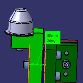
Fig Length Calculation for the length of the screw
To fix the pin retainer and shims need to use the standard screws we need to find the length of the screw using the above-mentioned formula
The highlighted surface shows the fig is the [distance b/w the surface of the part of the first surface of the other parts
Since the given tap hole id M10 & the distance is 30mm as shown in fig
Length of the screw = {1.5 x(stud. Hole size0]+{distance b/w the surface of the part of the first surface of the other parts}
Length of the screw= 1.5 X10 +30=45mm Allen cap screw
Then the standard size of the screw should be 40mm for connecting the pin retainer &shims blocks for example
MATERIALS USED:
In general, the materials used for pins, pin retainers, shims, shim block, blades & risers are:
A Pin: C45. EN31 SAE 8620 Steel, etc.
B.Pin retainer: Steel/ASTM A-36, SS type 303 or 304, etc.
C . Shims/spacer: SAE 1010 CRS FULL HARD, COLD ROLLED STRIP STEEL S.A.E. 1010 FULL HARD, SAE 1020 HRS, etc.
D.Shim block: STEEL ASTM A-36, NM Stainless, STEEL ASTM A-36, SS type 303 or 304, etc.
E Blade: STEEL ASTM A-36, etc.
F.Riser: STEEL ASTM A-36, etc.
HARDNESS
In general, the hardness of the materials for pins, pin retainers, shims, shim block, blades & risers are:
- 55-60 HRC/58-62 HRC to a depth of 0.5-0.7 mm after grinding.
SURFACE FINISH:
in general, the hardness of the materials for pins; pin retainers, shims, shim blocks, blades & risers are
A Pin: Chrome plating, Zinc coating, Pins with TiN codes shall have 1 to 2 microns of nitride added to surfaces
B.Pin retainer: BLACK OXIDE FINISH, No black oxide finish for "SS TYPE components (SURFACES TO BE FLAT, PARALLEL & PERPENDICULAR TO O WITHIN 0.015 T.LR).
C Shims/spacer: BLACK OXIDE FINISH (SURFACES TO BE FLAT AND PARALLEL TO WITHIN 0.015 mm T.I.R).
D.Riser: SURFACES TO BE FLAT, PARALLEL & PERPENDICULAR TO WITHIN 0.015 TIR
PIN TOLERANCE
The pin tolerance for geo pin will be of closer tolerance Le-0.15mm & for respot pin is of -0.26mm.
PURPOSE OF PIN UNIT
- As by the 3-2-1 locating principle, the introduction of two pins helps to arrest the 6 degrees of freedom (4 axial & 2 radial movements) whereas the other 6 degrees of freedom are arrested by introducing a minimum of three supports
- Typically, the locating pins are used to locate a body part in a position sufficiently accurate to execute a welding process.
- The body part is constrained by a set of appropriately locating pins so total constraint by locating pin should be fully constrained at all times to prevent any movement
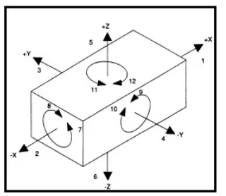
Fig Degrees of freedom
FUNDAMENTALS OF PIN UNIT DESIGN:
It is necessary to have two pins to locate a car panel. And here one pin must arrest 4 way (Le 4 translation) & the other must-have arrest 2 way (Le 2 rotational) of a car panel.
- The pin should engage 3 to 5mm from the car part entry surface.
- All pins should be accommodated with 2-way adjustable shims irrespective of the direction of arresting.
- A round pin should be used in case of 4 way arresting of the car panel if the hole is round.
- The round pin can be used for 2 way arresting of car panel only if the hole is slot
- A diamond pin should be used in case of 2 way arresting of car panel if the hole is round.
- A diamond pin should be used in case of 4 way arresting of the car part if the hole is slotted.
- The axis of the car panel hole & the axis of the pin should be the same in general.
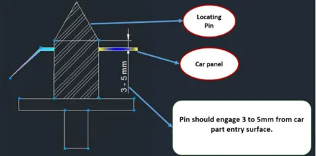
The fig shows 1st point of fundamentals for the pin unit design
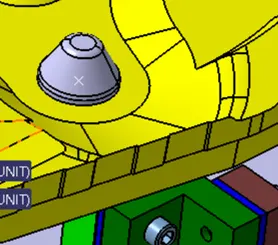
The ground pin should be used in case of 4 ways arresting of car panel if the hole is round
Fig shows the 3rd point in the fundamental of pin unit design
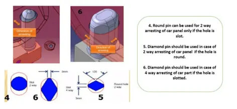
Fig shows the 4th,5th&6th point in the fundamentals of pins units design
Types of pin units
There are 2 types of pin units are there
- Fixed pin unit
- Retractable pin unit
FIXED PIN UNIT
- Fixed pin units is the unit designed to locate the car panel using pins
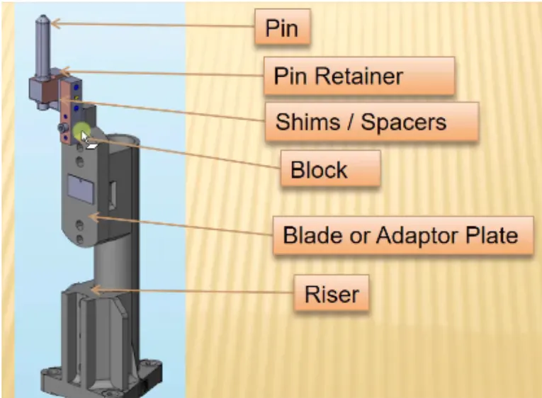
- Pins, pin retainers, shims, blocks, blades, risers are the parts of fixed pin units in general
- Pin retainers are used to hold the pin firmly
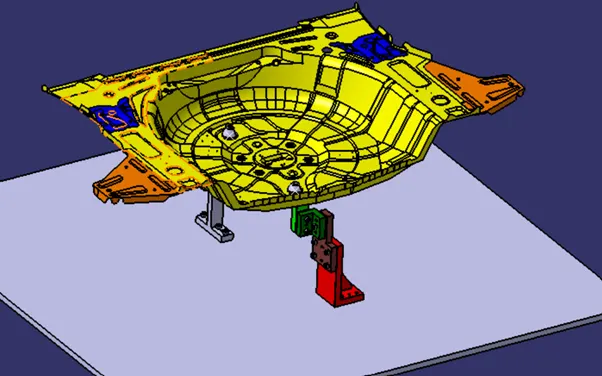
This fig shows the principal locating point(PLP) in the fixed pin unit
Principal locating points are the holes in which we locate the panel.PLP holes must be very much precise
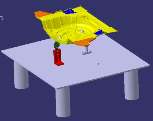
Fig shows fixed point unit with panel
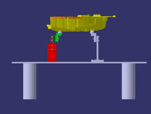
Fig fixed pin unit with panel (side view)
Parts of fixed pin
PIN (P001_Z01_ST01_01_00_FIXED_PIN)
There are 2 types of locating pins are used
- Round pin
- Diamond pin
- The pin is the part that is located on the panel
- The pin should engage 3-5 mm from the panel entry surface
- Typically the locating pins are used to locate body parts in a position sufficiently accurate to execute a welding process
- The body parts are constrained to be fully constrained by a set of apparated locating pins so total constraint by locating should be fully contained at all times to prevent any movement
- There are several pins designs are used
- The pin can either be a make part or a standard part also. Below I have shown the commonly used pins.
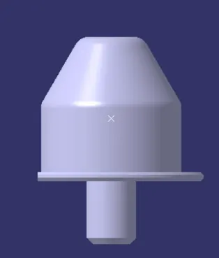
One of the most common pins is a stepped pin with either a small or large head
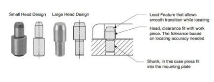
Fig types of locating pin
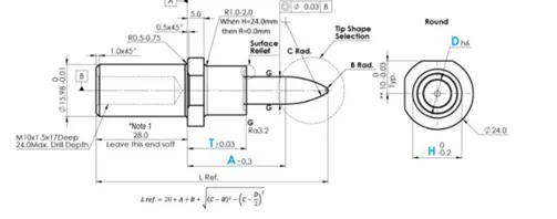
NAAMS standard locating pin (6 ways small head)
Consideration while designing & manufacturing pins:
- The pin should have a grinding surface on the shaft with fits on to which the pin retainers will be fitted.
- The mounting surface of the pin should be finely machined.
- A pin should have a step machine surface to lock the rotation, which matches with the pin retainer.
- The mounting surface of the pin retainer to the blocks should be machined.
- All machined planes should be perpendicular to the axis of the pin shat.
- Pin must have a fastening provision like a tapped hole from the bottom or a v-grove from the side
- A pin must be hardened (55-60 HRC) & black oxide finishes in general.
PIN RETAINER
A pin retainer is a part that holds the pin in position, the pin retainer can either be a make part or standard part also
Pin retainer is used to hold the locating pins firmly
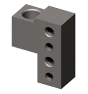
NAAMS standard -pin Retainer(APR336)
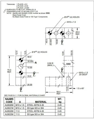
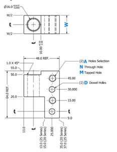
Consideration while designing & manufacturing pin retainers:
- Pin retainer should have a hole with a fit, on to which the pin will be fixed.
- The pin mounting surface of the pin retainer should be finely machined.
- The pin mounting surface of the pin retainer should have the step to lock the rotation of the pin.
- The pin mounting surface of the pin retainer to the blocks should be machined.
- The pin retainer will be fixed to a block or an L-block to the riser with 2 dowel holes & at least one screw hole to maintain the tolerance.
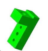
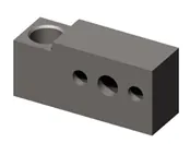
Cad models of different types to make pin retainer used in this project
SHIMS
- Shim is generally used to adjust the design to manufacturing deviation.
- In general, A shim is a thin and often tapered or wedged piece of material used to fill small gaps or spaces between objects.
- Shims are typically used to support, adjust for better fit, or provide a level surface.
- Shims may also be used as spacers to fill gaps between parts subject to wear.
- Shims are the small parts that come with thicknesses of 0.1mm,0.2mm,0.5mm,1.0mm, etc.
- These will compensate the stack up a tolerance which reflects at the mylars.
- We give tolerance to all parts of the fixture. Due to this tolerance, the mylars will either lift moves down from their defined position.
- To adjust the mylars for getting the defined position we use shims. • Shims will be added above the mylar for adjusting according to tolerance.
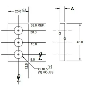
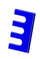
NAAMS standard shim pack/spacer cad model make shims used in this project
Applications of Shims
- In automobiles, shims are commonly used to adjust the clearance or space b/w two parts, for example, shims are inserted into or under bucket tapped to control valve clearance .clearance is adjusted by changing the thickness of the shims
- In assembly and welding fixture precision metal shims are used b/w two parts so that the final production parts are created within the production drawing specification
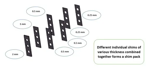
Exploded view of shims pack
L-block/shim block
A plate-shaped L is called an L block. This part is used as a connection between mylar and Blade. Generally, L blocks are used to provide shimming. L blocks don't need to be only used for shimming, their uses change as per the requirements, At some places, it is used just to connect one part to another. Similar to the L block one more block is used which is in the shape of T. So this block is called a T Block.
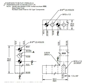
NAAMS STANDARD L-block
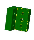
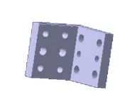
CAD model of-block in thus projects
RISER :
The part which is mounted on the base plate and holds a clamp or pin cylinder on it is called Riser. Riser can be Standard Part or manufactured part, it varies from project to project. A riser can be a Single part or welded part. Standard risers also have various shapes and sizes.
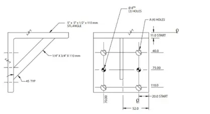
NAAMS standards
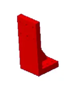
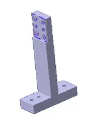
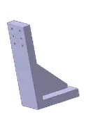
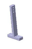
CAD model of RISERS in thus projects
BLADE :
The plate which connects Riser to the Clamp cylinder is named Blade. This plate plays an important role in building the unit. The plate can be of any shape. But we need to keep in mind that the plate should be as compact as possible.
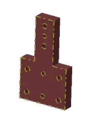
DOWEL HOLES & MACHINED SURFACE IN PIN UNIT
All make parts which are to assemble with tolerance should be designed with 2 dowels holes at least 1 to 6 thread holes or free holes .and to be finely machined for the mounting surface with 3 to 5mm step machined surface which is parallel or perpendicular to the surface
BORUGHT OUTS
brought out parts are some of the parts or components which are used in the project with out designing the part we can import the part from exsisting part from the suppliear
they are
- Cylinders
- Fastners
- Cylinders
- Stud 1:- pneumatic in aluminum block design with a precision guide of the position rod ,secured against rotating, compact housing made from high-strength aluminum with mounting option on several sides. drive mechanism with a circular-section cylinder for trust force and extraction force of approx 350/250N. total stroke 55mm integrated inductive sensing system (T12)
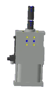
- Fastners
- Hexagon allen cap screw(std:EN_ISO-4762_STEEL HEXAGON CAPSCREW)
- Washer(Std: EN_28738_8_STEEL GRADE_CLEVIS_PIN_PLAIN_WASHER)
According To The Given Project Design Approach
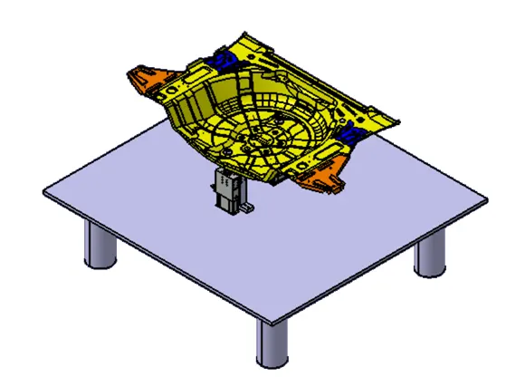
According to my project, I got a panel and a tool base for the panel this is the input port data for the project
Inputs
Panel (FLR_PNL_COMPONENT.1):
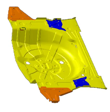
Panel FLR_PNL_COMPONENT.1
Base (Sample_Base_Unit):
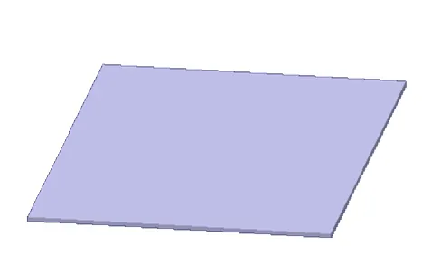
Fig: Base unit(Sample_Base_Unit)
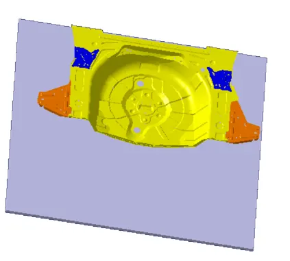
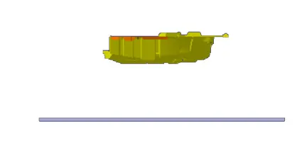
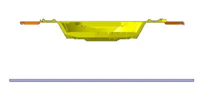
different views of the input data
To start the project first part is to design FIXED PIN UNIT AND RETRACTABLE PIN UNITS my first step Is to start
1. Fixed pin unit
2. RETRACTABLE PIN UNIT
1.FIXED_PIN_UNIT
To start the project in catiaV5 and insert a project file name the project as P001_Z01_ST01_00_00 in this project add required sub-projects and components and parts according to the use of the parts to build
And import the input or CAD data to the project and name as P001_Z01_ST01_00_00_COMPONENT and save the files with the save management option to save all the parts and components in a single folder
The next step to design the pin for that I created a new project and name as P001_Z01_ST01_01_00_FIXED_PIN and save the file in the project add parts file and name according to the use required in my case I took two holes to draw a pin which shown below images
Pin unit (P001_Z01_ST01_01_01_PIN)
Started with sketching the pin
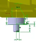
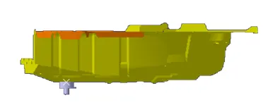
Fig Pin with a panel
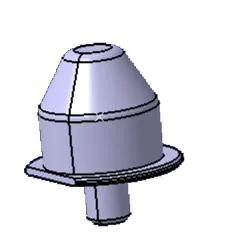
Fig pin without panel
RETAINER(P001_Z01_ST01_01_02_RETAINER)
When the pin was designed the next step is to design the supporting components to the pin that is retainer add a new part to the fix pin project and name as(P001_Z01_ST01_01_02_RETAINER) and start the design of retainer which in below fig
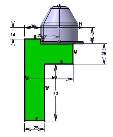
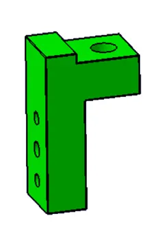
Fig Retainer with and without pin
SHIMS
I used standard shims so I named them as shims only
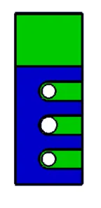
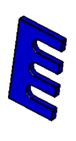
Fig Shims
L-BLOCKS(P001_Z01_ST01_01_03_L-BL0CK)
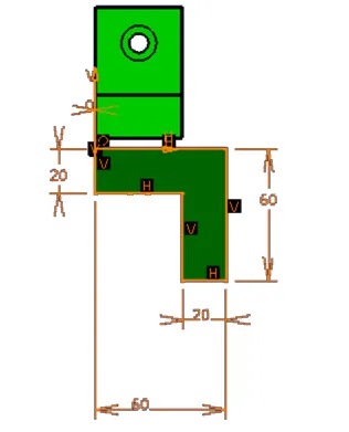
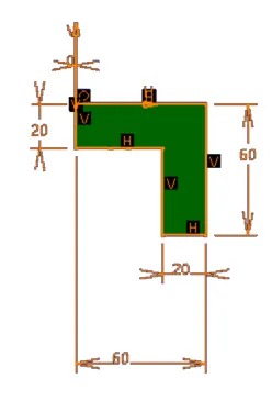
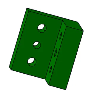
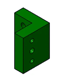
Fig L-BLOCK
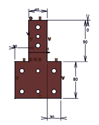
Blade
The part which connects the L-block and the Riser these components are available standard
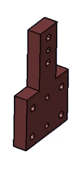
Riser(P001_Z01_ST01_01_04_RISER)
The riser is the part that connects to the base and gives support to the panel the same process import a part and name as (P001_Z01_ST01_01_04_RISER) and start a sketch of the riser
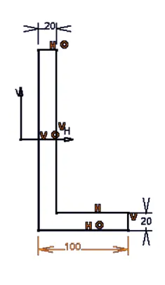
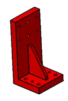
Fig Riser
Final fixed pin unit
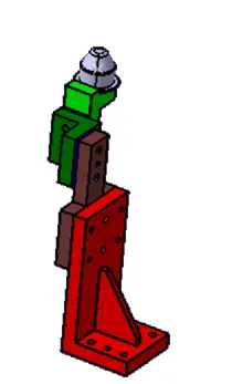
fig Fixed pin unit
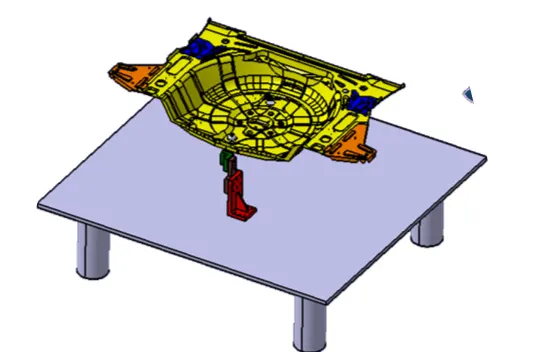
Fixed pin unit with Panel and Base
THE SAME PROCEDURE TO DESIGN THE SECOND FIXED PIN UNIT add new project and name as (P001_Z01_ST01_01_00_FIXED_PIN.1)
PIN (P001_Z01_ST01_01_01_PIN-1)
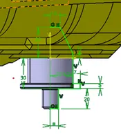
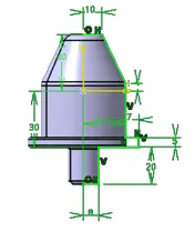
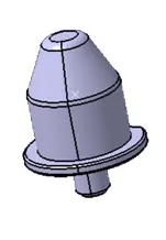
Pin unit with and without panel
Retainer (Copy (1) of P001_Z01_ST01_01_02_RETAINER)
To reduce the time and manufacturing cost I used the same retainer
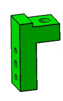
Fig Retainer
Raiser (P001_Z01_ST01_01_02_RISER-1)
For this kind fixed pin unit not required of L-blocks and Blades for that I directly connected with Riser
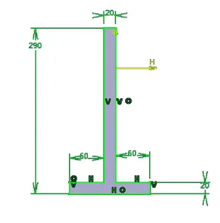
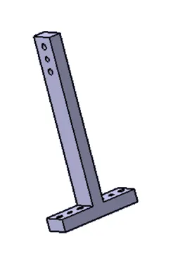
Fig Raiser
Final 2nd type of fixed pin unit
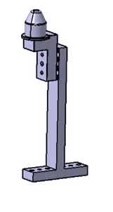
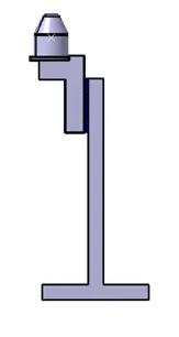
Fig 2nd type of Fixed pin unit
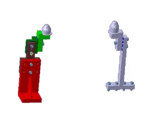
Fig Two models of fixed pin units
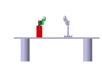
Fig Front view
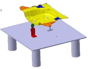
Fig Fix pin unit with panels and base
RETRACTABLE PIN UNIT
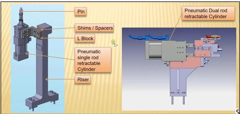
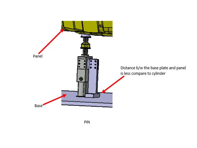
The steps and procedure is the same as fixed pin unit just we need to import some standard parts like a cylinder which is pre ejecting parts and for this design cylinder height is more than the distance b/w the panel and the base plate so that I made a hole with some clearances to fix the cylinder
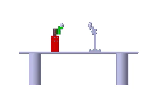
FIXED PIN FINAL ASSEMBLY
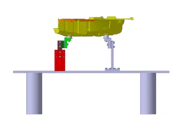
FIXED PIN ASSEMBLY WITH PANEL & BASE
RETRACTABLE PIN UNITS
I kept the project name as the same (P001_Z01_ST01_00_00) in the parts changed the names separately
Then insert the components in the assembly and with panels (P001_Z01_ST01_02_00_ RETRACTABLE _PIN_UNIT)
Pin unit(P001_Z01_ST01_02_01_RECTACTABLE_PIN)
it is also the same as the fixed pin type but some changes in retractable pin units like a cylinder.
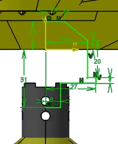
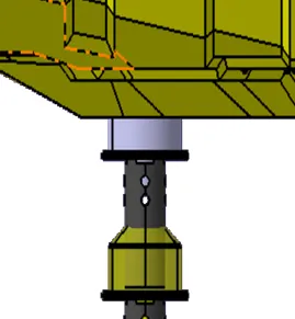
Fig Final pin
Cylinder
It is a pre-existing part so I imported it from the TUNKERS.then adjust the retraction was working with sufficient in b/w pin and panel
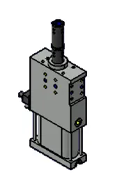
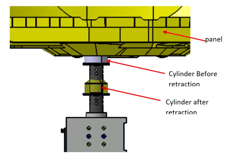
Fig cylinder
L-block(P001_Z01_ST01_02_02_L-Block)
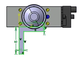
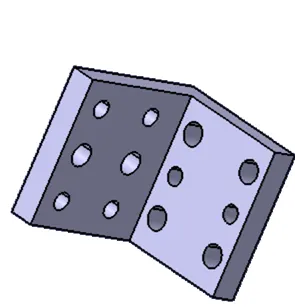
Fig L-block
Riser (P001_Z01_ST01_02_03_RISER)
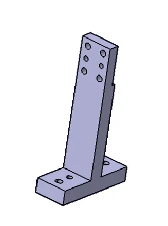
Fig Riser
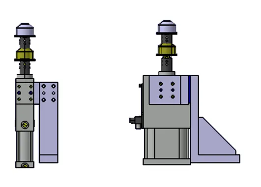
Fig Final retractable pin unit
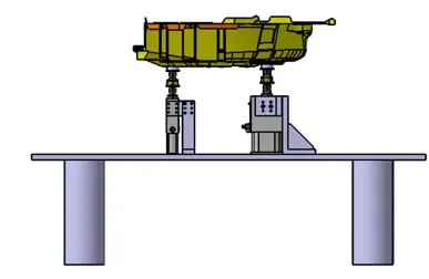
Retractable pin unit with panel and base
Conclusion
Hence as per the design fixed pin unit was named as (P001_Z01_ST01_00_00_FIXED_PIN_UNIT) and the 1st pin unit was named as (P001_Z01_ST01_01_00_FIXED_PIN) and the second fixed pin unit was named as (P001_Z01_ST01_01_00_FIXED_PIN.1).In the same way, a retractable pin was named as(P001_Z01_ST01_00_00) And retractable pin unit 1st and 2nd named as (P001_Z01_ST01_02_00_ RETRACTABLE _PIN_UNIT), ( P001_Z01_ST01_02_00_ RETRACTABLE _PIN_UNIT-1)with the different pin, pin retainers, blades risers,shims, cylinders are designed using CatiaV5 Successfully