Week - 4 - Crash Box Simulation
Aim:
Simulation of a crash box crashing on to a rigid wall.
Abstract:
A crash box is an energy-absorbing structure that reduces the damage to critical and expensive parts of the car and the passengers in the event of a vehicle collision. In this simulation, we are using a simple rectangular sheet-metal box of thicknesses 1.2mm and 1.5mm to hit a rigid wall at a speed of 56.33 kmph. After the impact, either of these two scenarios might happen 1. the crash box fails and crumbles 2. the crash box rebounds from the rigid wall.
We will compare the results for 1.2mm and 1.5mm thickness boxes and plot the stress, strain, acceleration graphs.
Procedure:
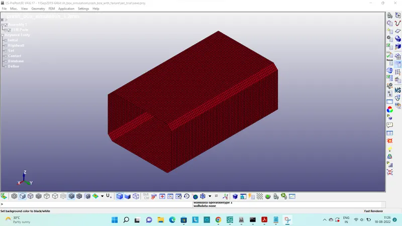
A. Open the given keyword file in LS-PrePost.
B. Create a Rigid Wall
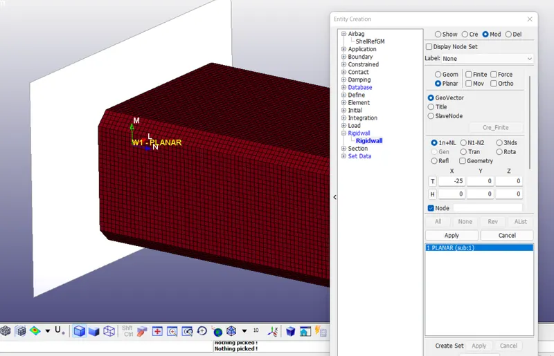
Create Entity > Rigid Wall was used to create the rigid wall for this simulation.
1n+NL, i.e one node and normal was used to place the rigid wall at a distance of 25mm from the crash box.
The normal of the rigid wall was defined as opposite to that of the velocity vector to prevent the crash box's penetration into the rigid wall.
C. Definition of the crash box material
MAT-024-PIECEWISE_LINEAR_PLASTICITY card was used to describe the material of the crash box.
Material Model 24: Piecewise Linear Isotropic Plasticity is capable of accounting for strain rate effects.
The following material data of STEEL was input.
- Density : 0.0078300 `(gm)/(mm^3)`
- Young's modulus : 2.070e+05 `(gm)/(mm.(ms)^2)`
- Poissons ratio : 0.30
- Yield strength : 309.79999 `(gm)/(mm.(ms)^2)`
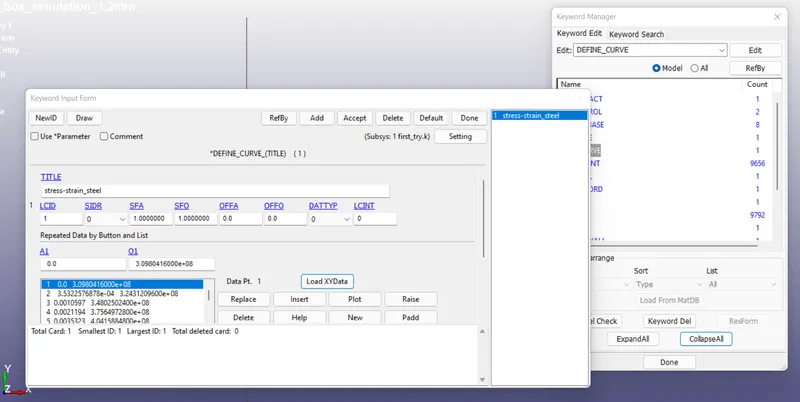
ETAN value was kept as zero since the stress-strain curve of steel was defined as follows:
The table with the stress and strain values was saved as a .csv file which was then loaded using 'LOAD XYDATA' option in the
DEFINE_CURVE card.
D. Shell section definition
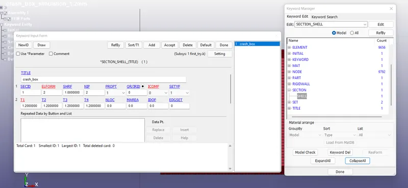
SECTION_SHELL was created with ELFORM and number of integration as 2.
Thicknesses of 1.2mm and 1.5 mm were given as two separate cases.
E. Definition of PART
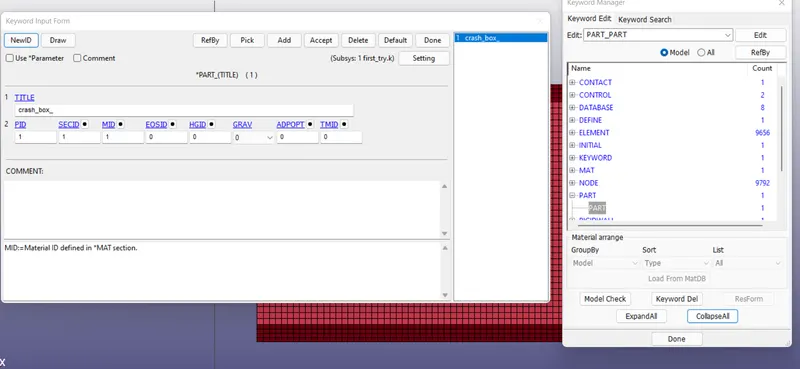
Previously defined material and section cards were assigned to the part.
F. Initial Velocity
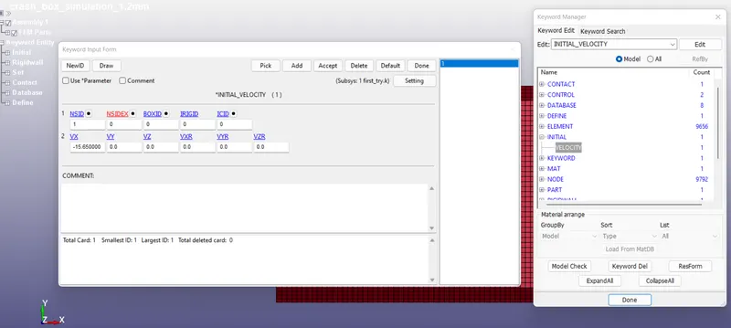
INITIAL_VELOCITY card was used for assigning an initial velocity of -15.65 mm/ms to the crash box in the x-direction.
G. Creating a cross-section plane.
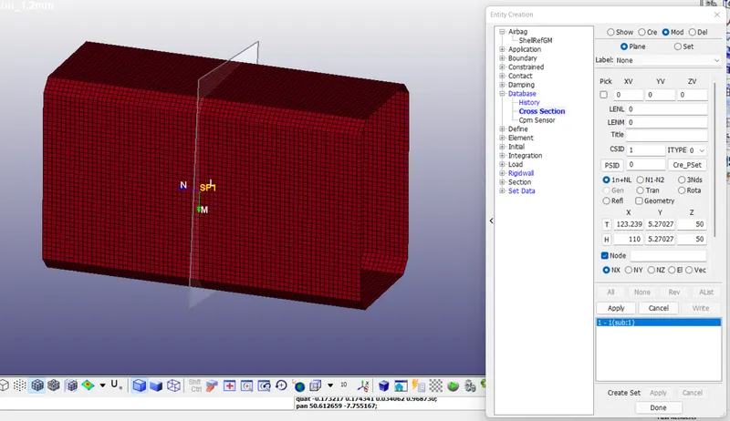
CREATE ENTITY > DATABASE > CROSS SECTION was used to create a cross-section to calculate the sectional forces in the middle of the crash box. 1n+NL option was used to define the plane. The normal of the plane was set in a direction opposite to that of the reaction force from the rigid wall so as to record the force magnitude.
H. Control Cards
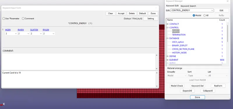
CONTROL_ENERGY card was used to calculate the hourglass energy.
Termination time was set at 10 milliseconds which gives ample time to study the effects on the crash box.
I. Database Options
ASCII outputs
Time-step of 0.5 ms was given for GLSTAT, SECFORCE, MATSUM, SLEOUT, and RCFORCE.
BINARY_D3PLOT was also set with a 0.5 ms time-step.
A cross-section plane was also created in the middle of the box as mentioned above in section G.
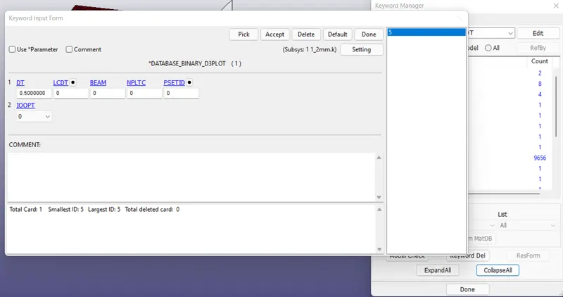
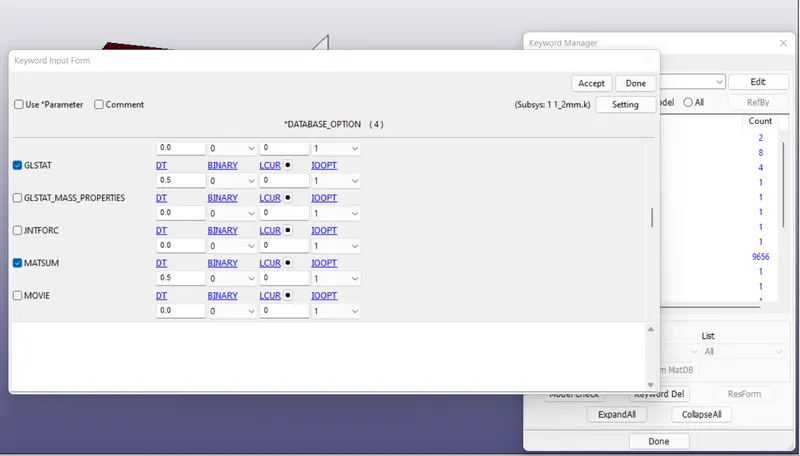
The file is now checked for errors using keyword > model check
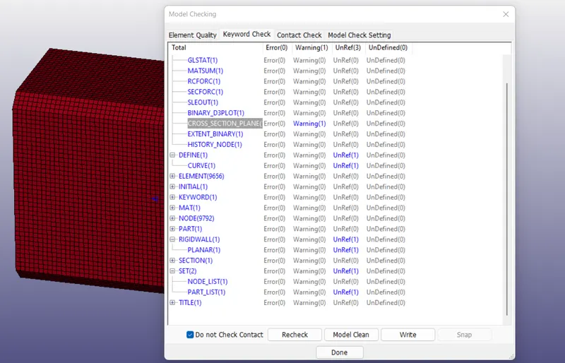
No errors were found and the file was saved as a keyword file.
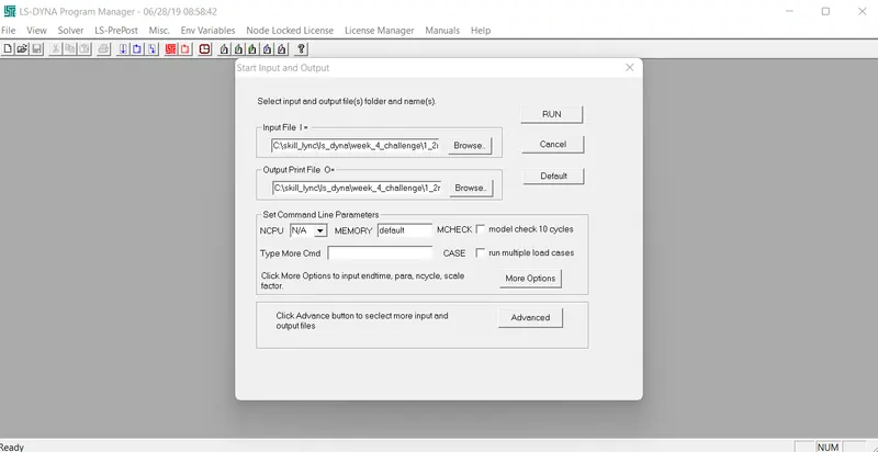
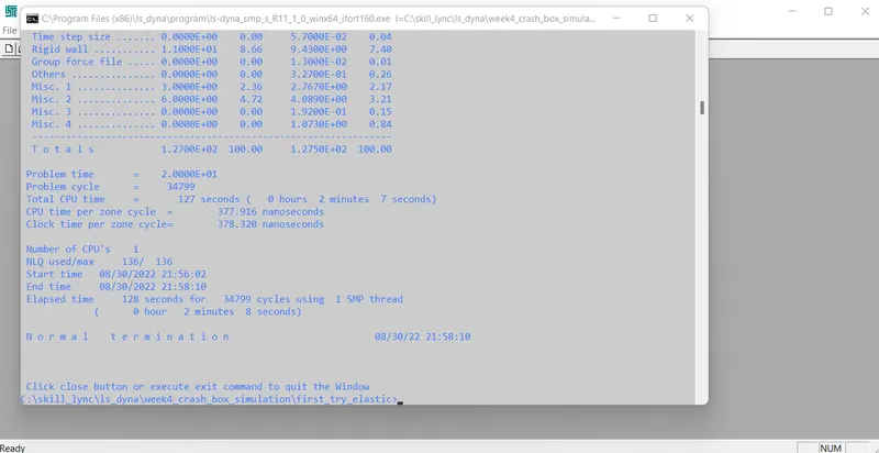
LS-DYNA manager was used to run the final key file. The process was completed with a normal termination.
The simulation was repeated with a shell thickness of 1.5mm as well.
RESULTS
The D3PLOT was opened in the LS-PREPOST.
Von-Mises stress distribution animation for the crash boxes are given below:
Please find the GIF file for the crash animation in the below link:
https://drive.google.com/drive/folders/1zibzq6a6aToJFvU0il_5hKhkPh9IISiF?usp=sharing
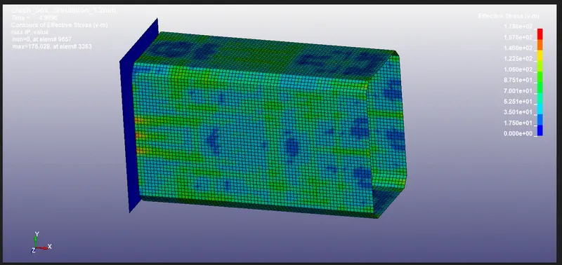
1.2mm thickness shell
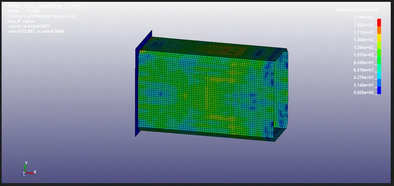
1.5mm thickness shell
Graph for the forces developed at the cross-section of the boxes are as shown below:
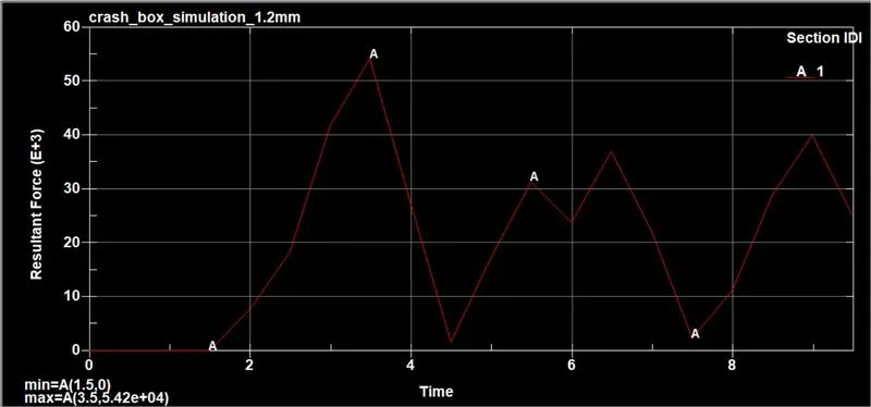
sectional force on 1.2mm thickness shell
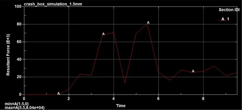
sectional force on 1.2mm thickness shell
The resultant acceleration plots of the same node on the crash boxes with 1.2 and 1.5 mm thicknesses are given below.
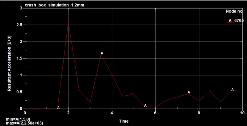
The resultant acceleration of the node on 1.2mm thickness box.
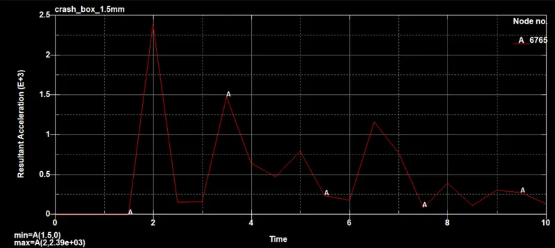
The resultant acceleration of the node on 1.5mm thickness box.
As seen in the resultant acceleration graphs for the crash boxes, the crash box with 1.5 mm thickness experiences a maximum acceleration of 2.39E+3 `(mm)/(ms)^2` at a time 2.0 ms as compared to a lower maximum acceleration of the 1.2mm thickness crash-box of 2.58 E+3 `(mm)/(ms)^2` at 2.0 ms. This could be attributed to the increased mass of the 1.5 mm shell box.
Maximum directional stress and strain along the length of the box.
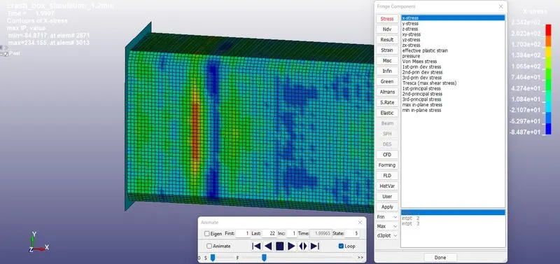
The maximum value of x-stress in the 1.2mm shell box is 234 MPa
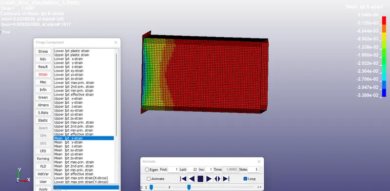
The maximum value of Mean Ipt x-strain in 1.2mm shell box is 3.389E-2 mm.
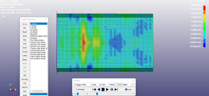
The maximum value of x-stress in the 1.5mm shell box is 253 MPa
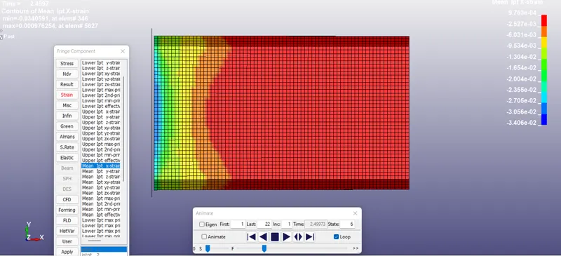
The maximum value of Mean Ipt x-strain in 1.2mm shell box is 3.4E-2 mm.
Stress VS Time Plot
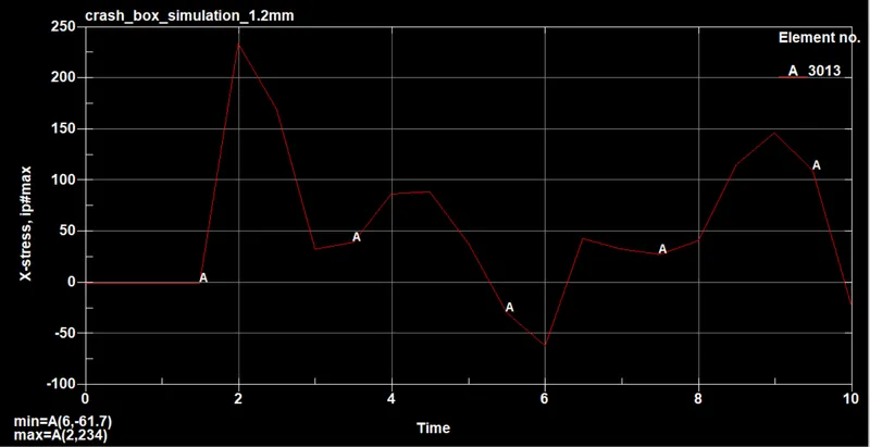
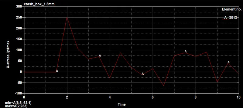
The stress vs Time plot of element id 3013 which was experiencing the maximum x-stress (from fringe component plot of x-stress) in both 1.2mm and 1.5 mm scenarios are plotted above. We can see that both graphs have a similar profile and that the maximum stress was generated at the time of the collision. 1.5mm thick shell box experiences a slightly higher maximum stress which could be the effect of more kinetic energy being dissipated during the collision because of its increased mass.
Strain VS Time Plot
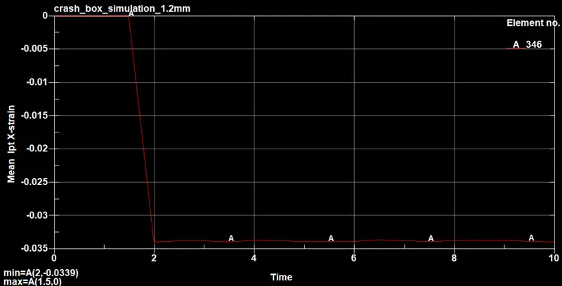
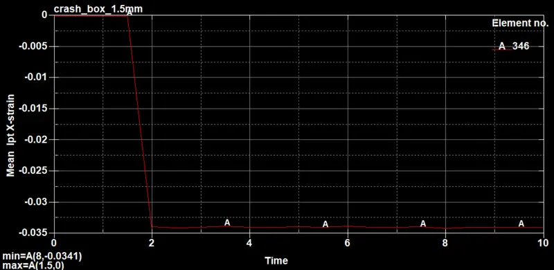
Similarly, comparing the maximum mean Ipt x-strain, the element 346 experiences a slightly higher strain in the 1.5mm thick box as compared to the 1.2mm thick box.
Energy Plots
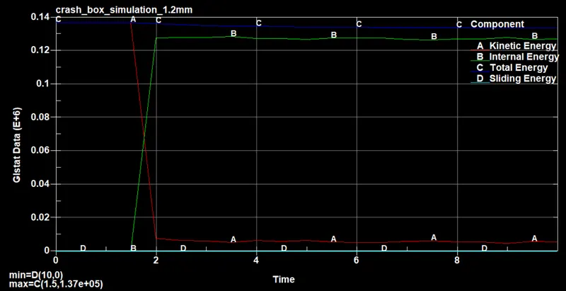
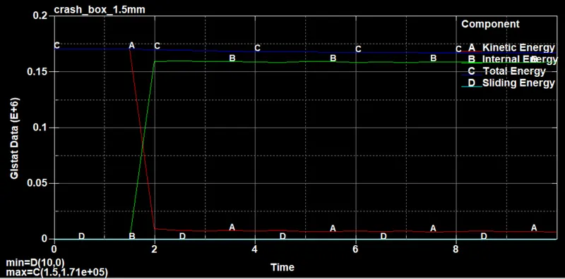
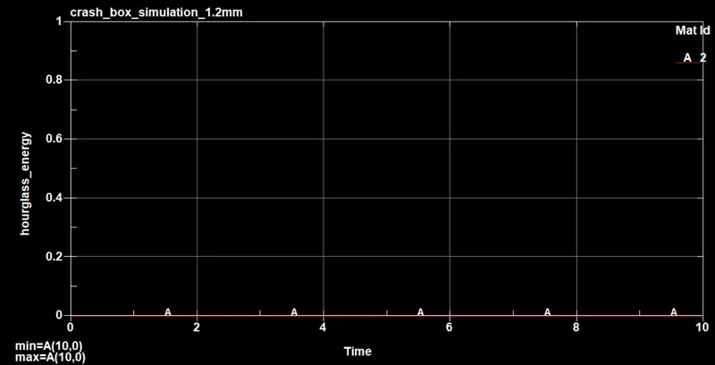
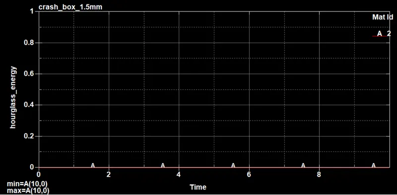
We can see from the energy plots that before the collision, the total energy was totally comprised of the box's kinetic energy and the internal energy of the box was practically zero. As the collision happens approximately at 1.5ms, we can see a large portion of kinetic energy starts being converted into internal energy while keeping the total energy constant. As expected sliding energy is close to zero and hourglass energy was found to be zero throughout.
CONCLUSION
The deck was prepared for the crash simulation using LS-PREPOST.
The simulation was run successfully in LS_DYNA.
Post-processing was done in LS-PREPOST from the output D3PLOT.
Comparisons were made for the crash boxes with 1.2 and 1.5 mm thicknesses.
The thicker crash box was able to absorb more energy with lesser deformation.