Week - 4 - Crash Box Simulation
Aim :
- To understand and create a rigidwall
- To understand how to change material cards based on elastic/plastic/brittle, Linear and Non Linear behaviour.
- To under Post processing basics.
Deliverables:
- Input .k file and output files (d3plot, glstat, sleout, rcforc)
- Animation of the final simulation
- Cross-sectional force generated in the middle of the crashbox (along its length)
- Acceleration plot of a node in the middle of the crashbox (along its length)
- Maximum directional stress and strain along the length of the crashbox (X strain, Y strain etc)
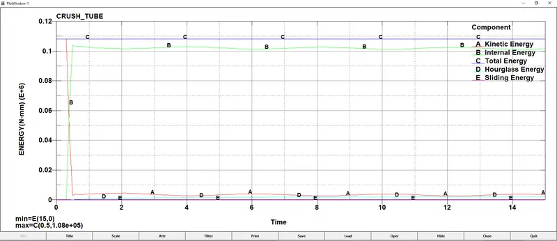
- Plot of all energies (total, internal, kinetic, hourglass, sliding)
- Compare the accelerations and stress/strain plots of 1.2/1.5mm crashboxes.
Procedure:
- Import the given file and define the necessary control cards: Accuracy, Hourglass, Energy, Termination, Timestep.
- Keep DT as 0.1, End time as 15 Sec, DTIni =0.1 = Initial time step and Energy values as 2.
- Create RIGIDWALL_ keyword using Geomewtric_FLAT under Rigidwall. It is easy to create rigidwall using Create Entity option which allows you to create and position the wall accordingly.
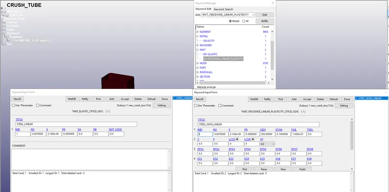
- Select material for the crashbox as steel. To simulate nonlinear material use Mat card 24 (Piecewise linear plasticity). Define thickness of the crashbox as 1.2mm in Section_Shell.
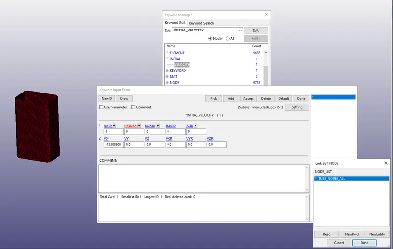
- Give Initial velocity for the crashbox around 50 kmph which should be around 13.889 m/s.
- The units used is gm-mm-ms
- The simulation satisfies 1st consition as It crashes on the rigidwall and rebounces completely.
- To run another simulation by increasing the thickness of the crashbox from 1.2 to 1.5mm add a Section with Shell thickness T1 as 1.5mm - To access animation of the final simulation click on the movie option under ASCII Keyword. ALternatively you can find this option in File section in the d3plot of the file.
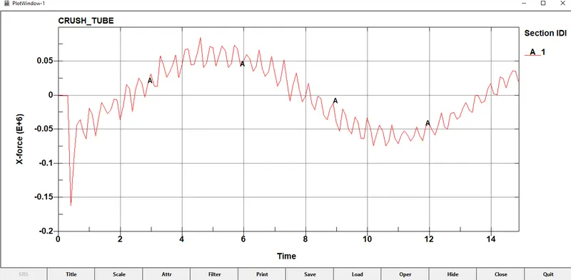
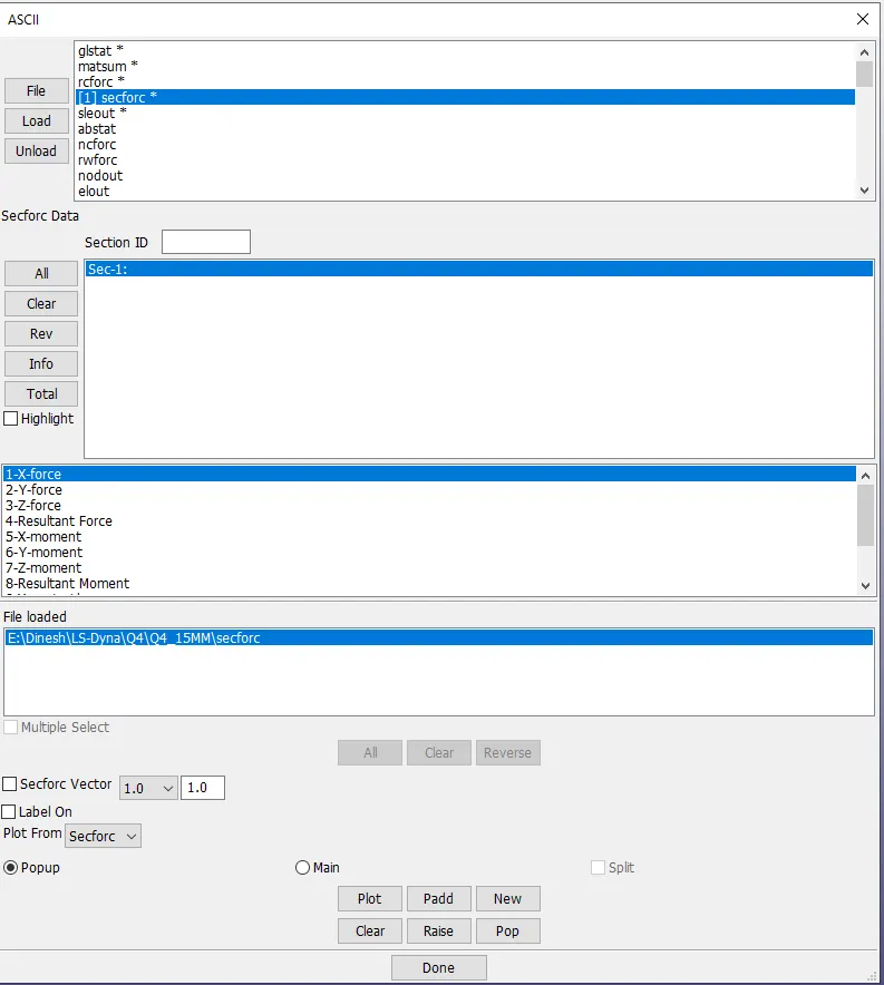
- Cross-sectional force generated in the middle of the crashbox (along its length) can be tracked by adding Cross-section from under Database Keyword. To access its outputs open ASCII keyword and click on SECFORCE. In ASCII output you can view in the fig shown below you can access which cross section to select and what forces to plot.
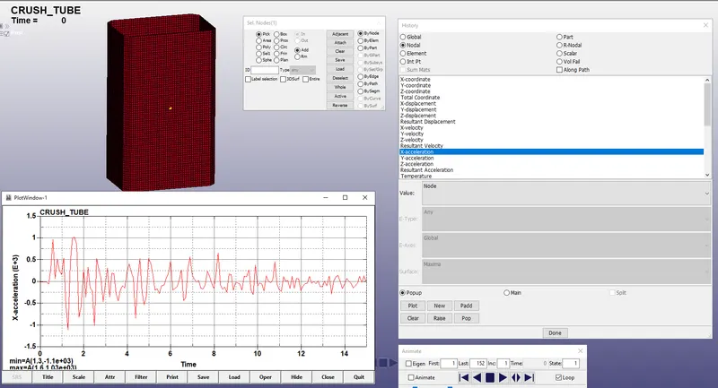
- Similarly select node option in ASCII output file and pick the node and plot acceleration of a node in the middle of the crashbox. (along its length).
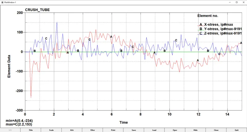
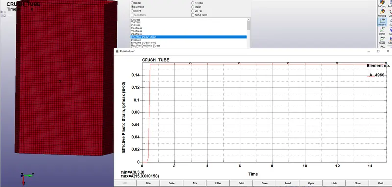
- Maximum directional stress and strain along the length of the crashbox (X strain, Y strain etc) can be found
- Plot of all energies (total, internal, kinetic, hourglass, sliding)
- Compare the accelerations and stress/strain plots of 1.2/1.5mm crashboxes.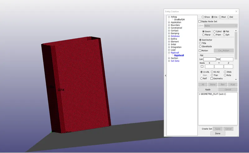
Deliverables:
- Animation of the final simulation
- Cross-sectional force generated in the middle of the crashbox (along its length)
- Acceleration plot of a node in the middle of the crashbox (along its length)
- Maximum directional stress
- Strain along the length of the crashbox (X strain, Y strain etc)
- Plot of all energies (total, internal, kinetic, hourglass, sliding)
- Compare the accelerations and stress/strain plots of 1.2/1.5mm crashboxes.