Week - 4 - Crash Box Simulation
CRASH BOX SIMULATION
Objective:
The objective of this project is to simulate and validate the outputs of a crash test for the given crash box by creating a rigid wall using *RIGIDWALL_ keyword.
Procredure:
Step - 1: Import the model to LS DYNA interface
The given keyword file is opened in LS DYNA. The model consists of a meshed rectangular box as shown.
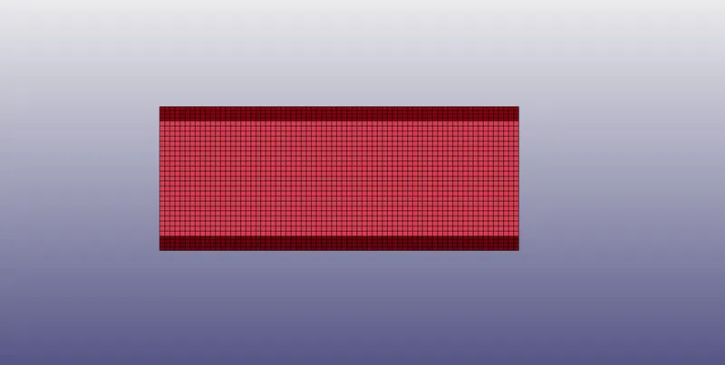
Fig: Imported Model
Step - 2: Set the unit system
Since the unit system is mentioned as gm, mm, ms so all the parameters have to be assigned according to it.
Step - 3: Creation of Rigid wall
A rigid wall must be created in order to crash the tube aginst the wall. The wall is created using Rigid wall Key word. Select create entity and select Rigid wall, since the required type of wall is planar so select the option and select the node at the edge and offset the wall by 10 mm apart from the tube as shown. The wall has to be perpendicular to the direction of the velocity in order to restrict the force.
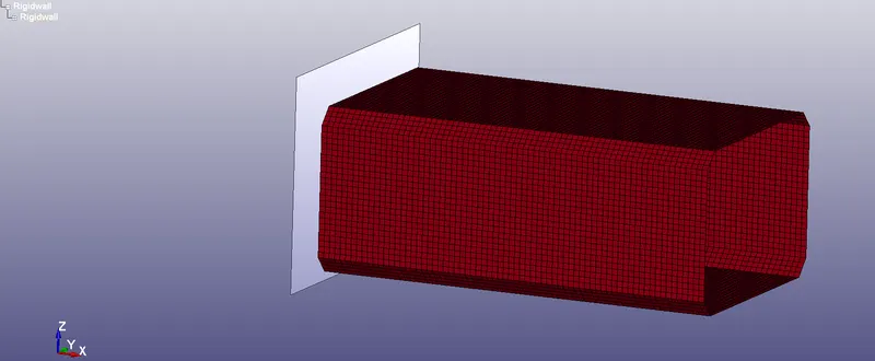
Fig: Rigid wall
Step - 4: Applying initial velocity
An initial velocity of 50 kmph has to be applied to the crash box. Since we are using the gm, mm, ms system of units the 50kmph has to be converted into mm/ms which will be 13.89 mm/ms. Go to create entity select initial velocity select all the nodes set the velocity as -13.89 in X direction the -ve value indicates the direction of velocity.
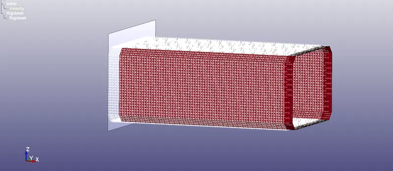
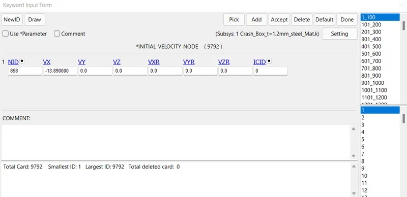
Fig: Initial velocity
Step - 5: Assigning the section
The elements of the crash tube are of shell elemnts so the section has to be assigned to those elements using the keyword section_shell and assign the thickness of the shell as 1.2mm.
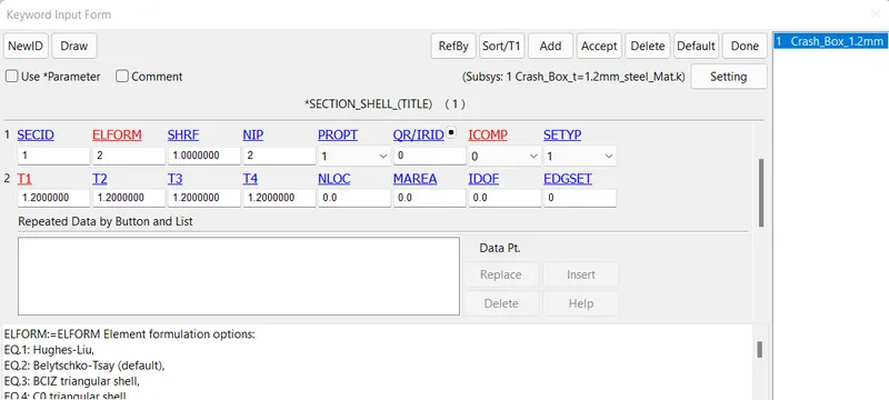
Fig: Section
Step - 6: Creation of a material card
Steel is considered as the material for the analysis is so MAT24 Piecewise linear plasticity material is preferred and the properties, values of the steel has to eneterd as per the selcted unit system as shown.
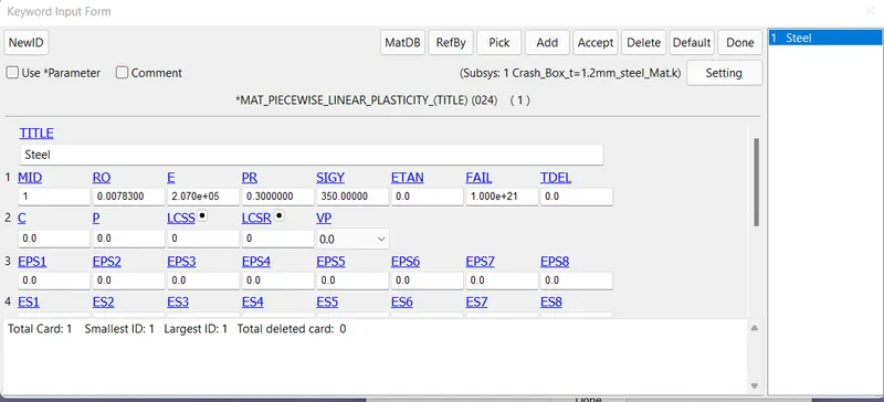
Fig: Material card
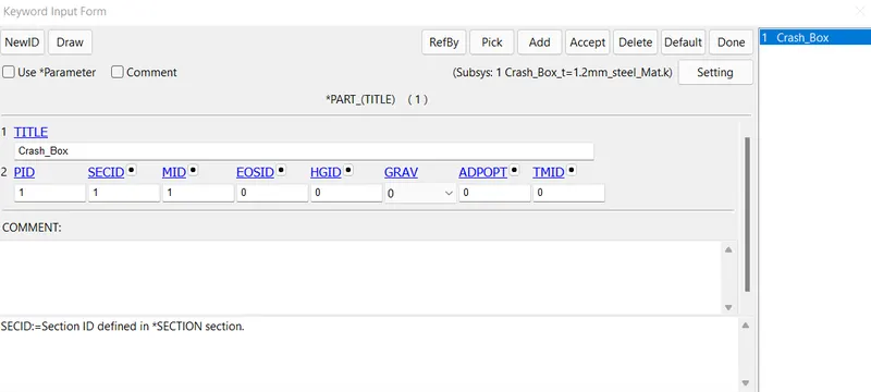
The created section and material card has to be assigned to the part as shown below
Step - 7: Contacts
During crash the tube undergoes deformation which makes the elements to collide each other by creating a self contact so single surface automatic self contact is assigned to the crash tube as shown below. select the slave as crash tube (No need to select master because of single surface).
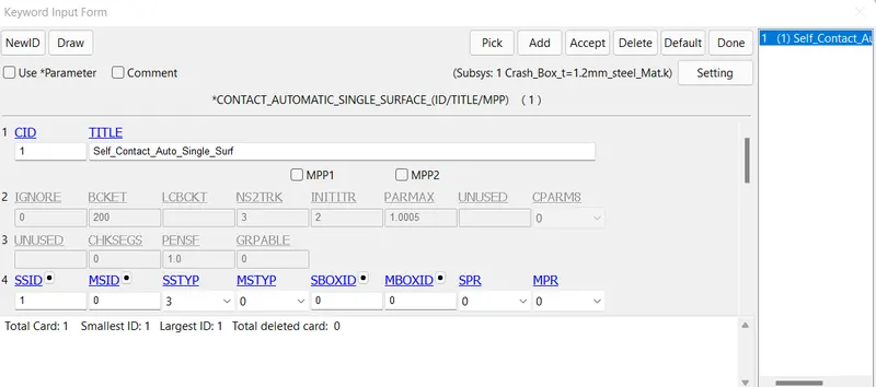
Fig: Self contact
Step - 8 : Control card / Termination
The applied velocity is 13.89mm/ms and the gap between the Rigid wall and tube is 10mm so it requires 0.72ms for the tube to make contact with the wall so the end time has be more than the calculated time enter the endtime as 10ms
`v =d/t`
13.89 = 10 / t
`therefore`t = 0.72
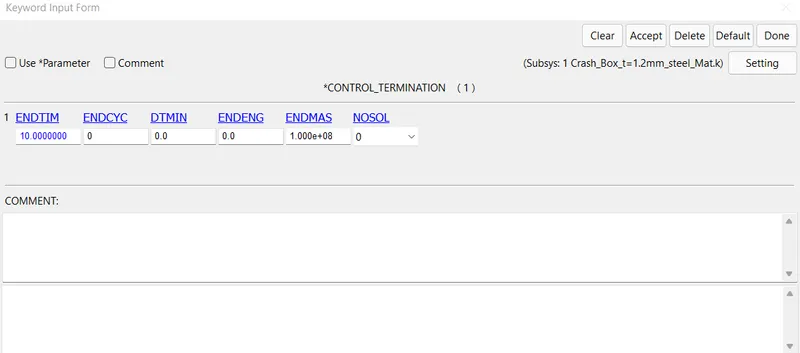
Fig: Control termination
Step - 9: Control energy and Hourglass
Create the cards for the control of hourglass and energy as shown below
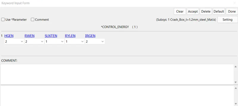
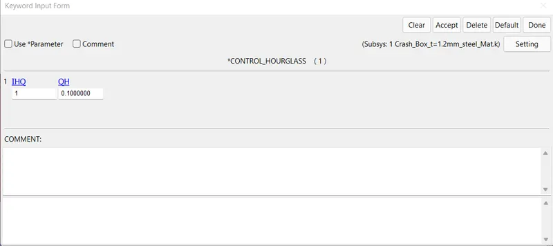
Fig: Control Energy and Hourglass
Step - 10: Creation of cross section
Create a cross section plane at the middle of the component in order to check the forces using create entity option as shown.
Create entity_Database_Cross section_Plane_Select the centre node_Apply.
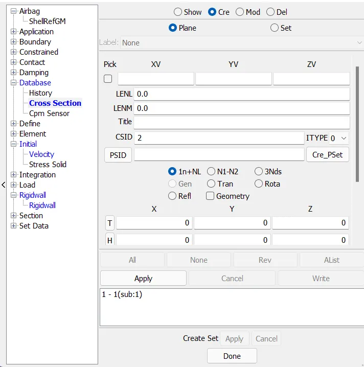
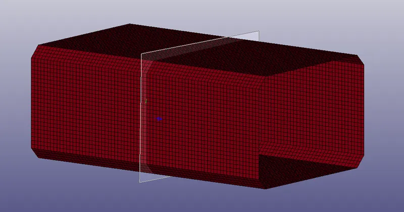
Fig: Cross section
Step - 11: Output cards
Request the output cards required (D3 plot and Ascii files like Matsum, Glstat, Nodout,Rwforc, Sec forc etc.) by entering the dt as 0.1ms as shown.
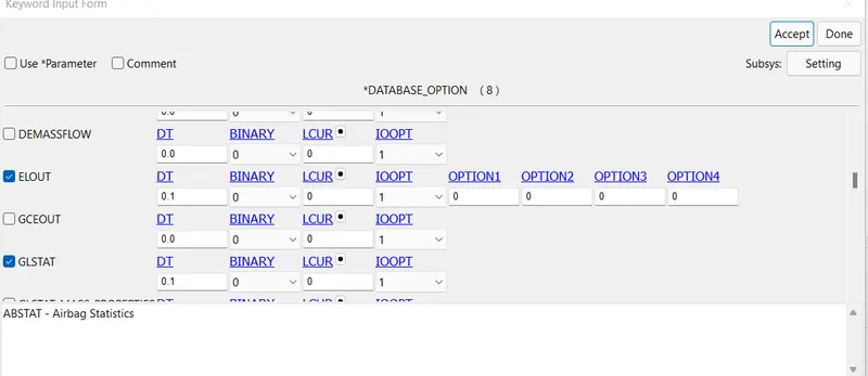
Fig: Output files
Step - 12: Keyword check
Run the keyword check inorder to rectify errors in the model keyword and run the model for processing.
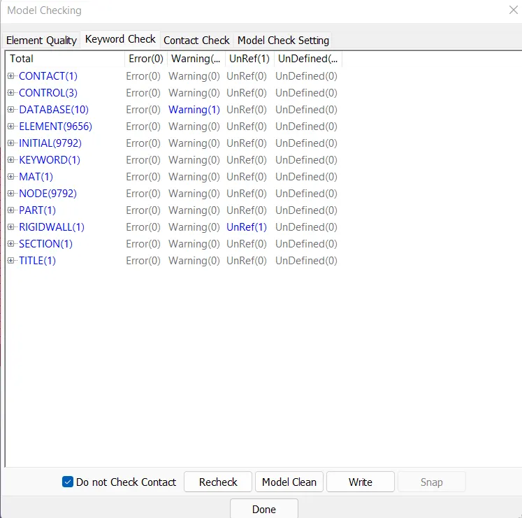
Fig: Keyword Check
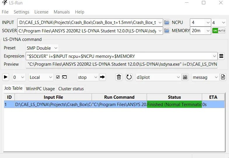
Step - 13: Processing of model
Run the keyword file in LS Run for the computation with the default settings as shown. Ensure the status for normal termination.
Result (Post processing):
Tube Thickness - 1.2mm
Stress in X-Direction:
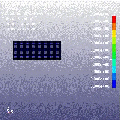
The maximum stress in the X direction of the tube was found to be 193.07Mpa and the minimum is -392.63Mapa(Compression)
Y - Stress:
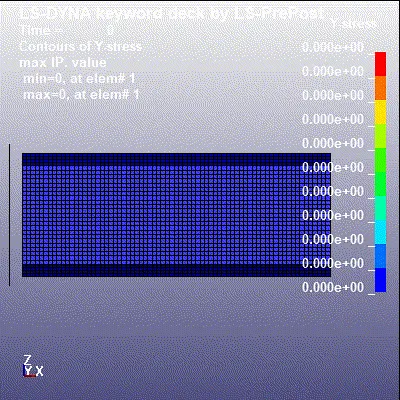
The maximum stress in the Y direction of the tube was found to be 275.11Mpa and minimum of -339.29Mpa (Compression)
Z-Stress:
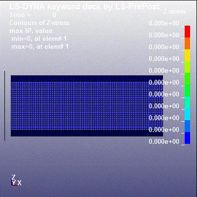
The maximum stress in the Z direction of the tube was found to be 312.84 Mpa and minimum of -302.28Mpa (Compression)
Von Mises Stress:
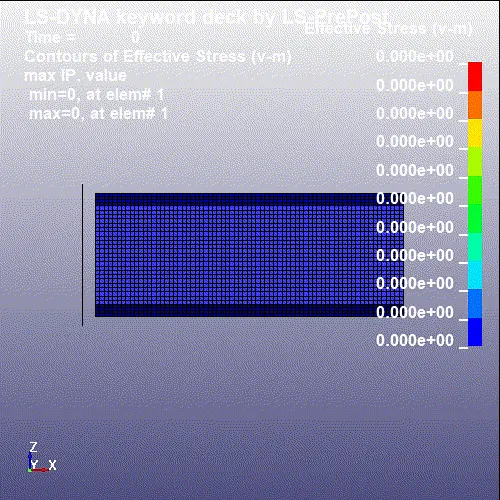
The maximum von mises stress was found to be 370.10 Mpa
Cross sectional force:
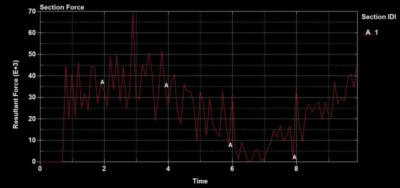
The resultant cross sectional force at the middle of the tube is found to be 70 X 10^3 N at 2.9ms as shown. The deformation starts at approximately 0.8ms where the value of force suddenly increases as shown.
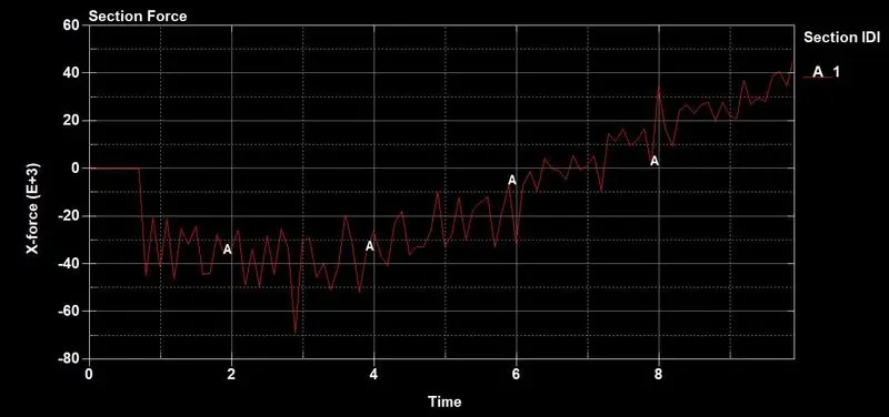
In the X direction the force is going to decrese because of the compressive action of the tube (Tube rebonds in the opposite direction of the force)
Acceleration:
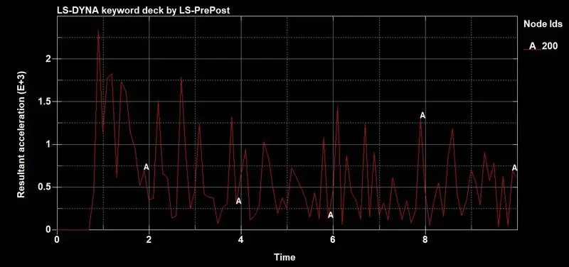
The maximum acceleration found in the middle of the tube is 2.6 X10^3 mm/ms2 at 0.8 ms during the impact.
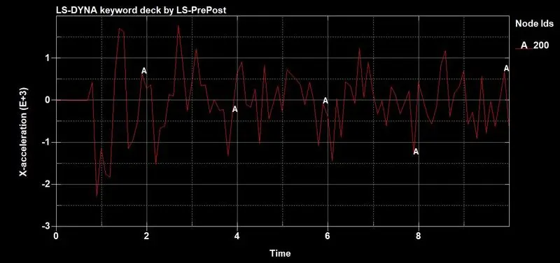
The maximum acceleration in X direction is found to be 1.7 X 10^3 at 2.3 ms as shown
Effective Strain:
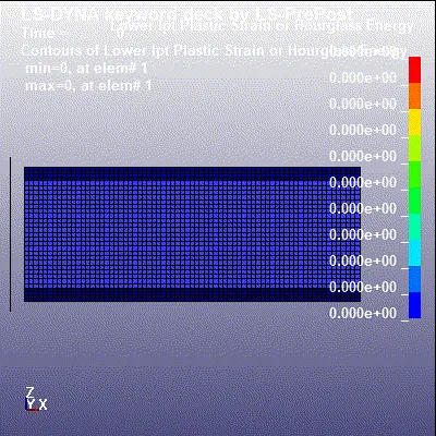
The maximum effective strain on the tube was found to be 0.02
X - Strain:
Y - Strain:
Z- Strain:
The effective plastic strain was found to be 0.02.
Internal Energy:
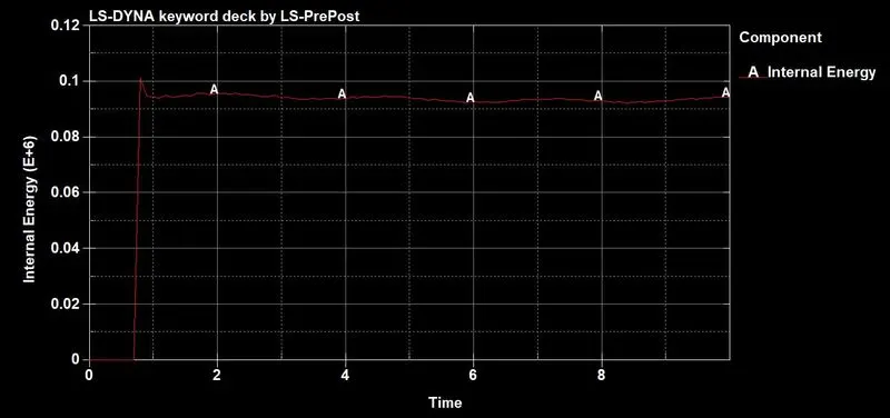
The maximum internal energy of the tube was found to be 1 X 10^5 N-mm at 0.8ms in which the tube crashes with the wall and it mainatins approximately same level of energy because of the bounce of the tube from the wall.
Kinetic Energy:
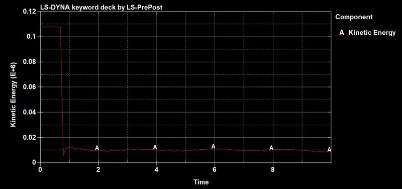
The maximum kinetic enery before contact was 0.108 X 10^6 N-mm and decreses to 0.01 x 10^6 due to the obastruction of the wall and crash
Total Energy:
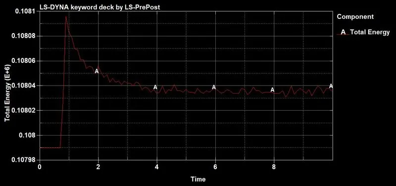
The total energy increses to 0.108095 x 10^6 N-mm during the crash respectively decreses as the kinetic energy of the tube decreses due to the crash
Hourglass Energy:
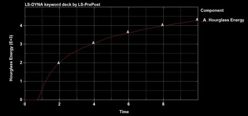
The maximum hourglass enery of the tube was found to be 4.25 x 10^3 N- mm which is around 3.9% of total energy which can be accepatble since its below 10% of Internal energy.
Sliding Energy:
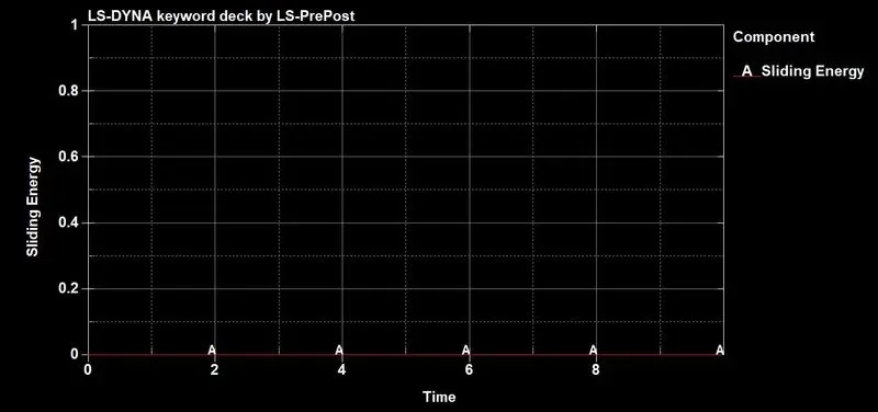
The sliding energy in the crash tube is negligible and close to zero and we can omit the effect on the results.
Output Results - Thickness 1.5mm:
X - Stress
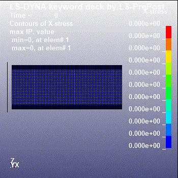
The minimum stress in X direction was found to be -389.61Mpa and maximum of 177.03Mpa
Y -Stress:
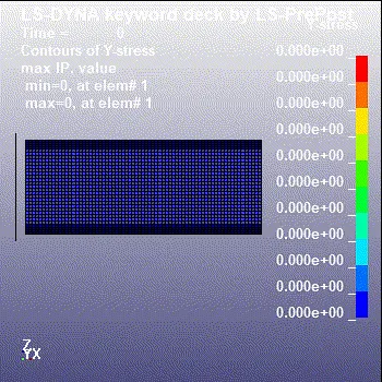
The maximum stress in the Y direction of the tube was found to be -374.84Mpa as minimum and maximum of 314.21Mpa
Z- Stress:
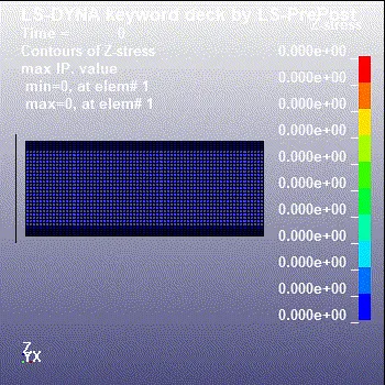
The maximum stress in Z direction was found to be 298.49 Mpa and minimum of -291.43Mpa.
Von Mises Stress:
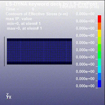
The maximum Von mises stress in the crash tube was found to be 370.12 Mpa .
Sectional Force:
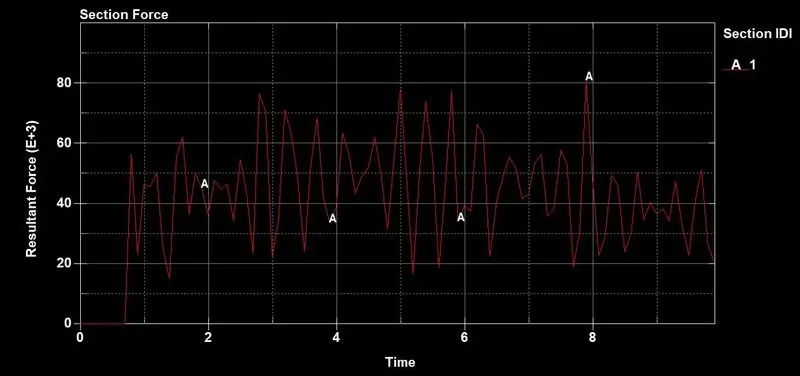
The maximum resultant force during the crash is around 80 X 10^3 N as shown.
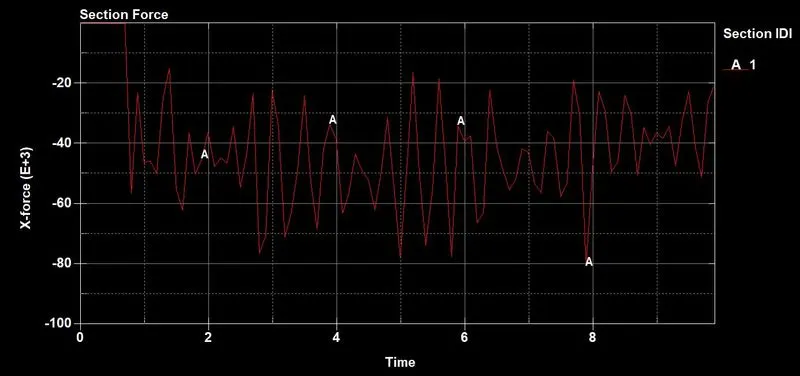
The force in the X direction reduces due to the crash and the minimum force was found to be -80 X 10^3 N.
Acceleration:
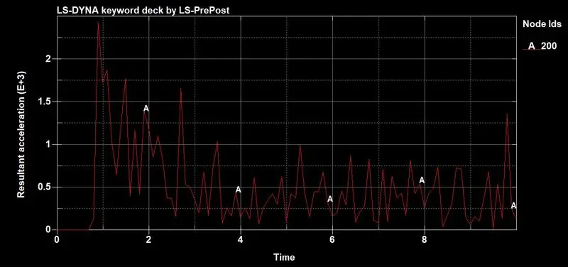
The resultant acceleration of the tube was found to be 2.8 X 10^3 mm/ms
Acceleration in X direction:
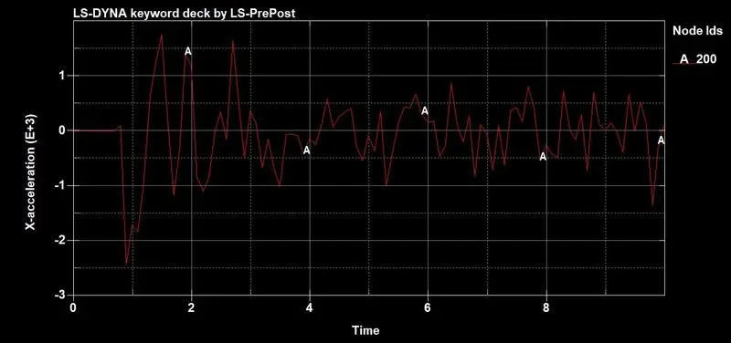
The maximum acceleration in x direction was found to be 1.7 X 10^3 mm/ms during the crash.
X - Strain:
Y - Strain:
Z- Strain:
The effective plastic strain of the tube was found to be 0.02
Internal Energy:

The maximum internal energy of the tube was found to be 1.25 X 10^5 N-mm at 0.8ms in which the tube crashes with the wall and it mainatins approximately same level of energy because of the bounce of the tube from the wall.
Kinetic Energy:
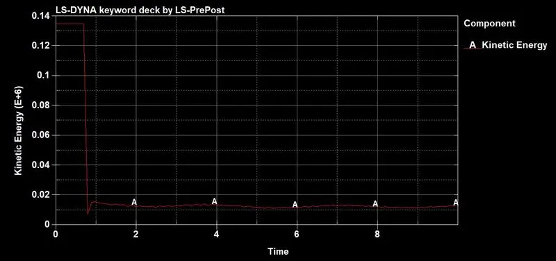
The maximum kinetic enery before contact was 0.135 X 10^6 N-mm and decreses to 0.009 x 10^6 due to the obastruction of the wall and crash
Total Energy:
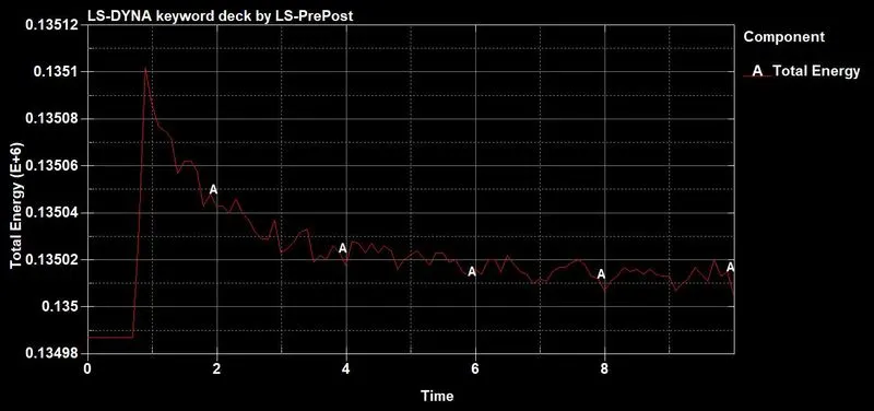
The total energy increses to 0.1351 x 10^6 N-mm during the crash respectively decreses as the kinetic energy of the tube decreses due to the crash
Hourglass Energy:
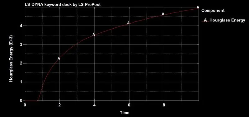
The maximum hourglass enery of the tube was found to be 5x 10^3 N- mm which is around 3.7% of total energy which can be accepatble since its below 10% of Internal energy.
Sliding Energy:
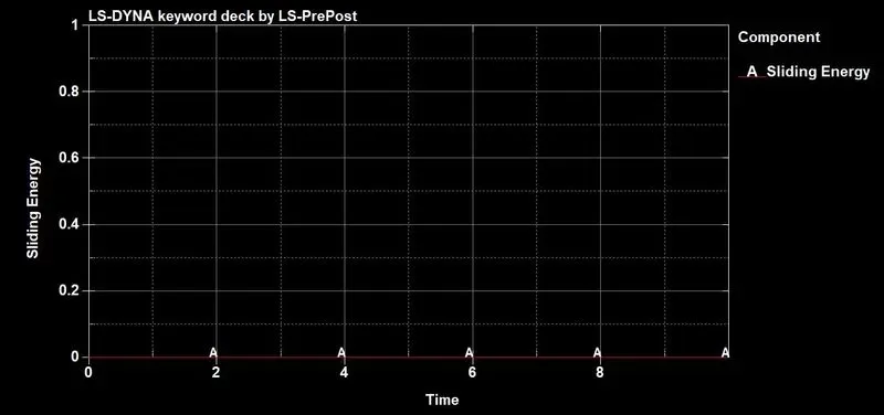
The sliding energy in the crash tube is negligible and close to zero and we can omit the effect on the results.
CONCLUSION:
While comparing the above output results the tube with 1.2mm thickness has greater stress (193.07 Mpa) when comared to the 1.5mm (177.03) in X direction. The increase in the thickenss of the tube makes it slightly rigid.
Because of this the output values of the Sectional force, Energies and Acceleration values for the 1.5mm tube is slightly greater than the 1.2mm thickness. The hourglass energy of the tube is also more than the 1.2mm tube thus the additional thickeness makes tube elements more rigid during the crash.
MODEL:
https://drive.google.com/drive/folders/1VlgBAnaKdDlrkJDpBjF25JeiwwY0s9AA?usp=sharing