Week - 4 - Crash Box Simulation
Aim: To create a Deck-Setup for the Crash Box and request for the animation file and time history file, and change the thickness of the crash box from 1.2mm to 1.5mm
Different assumption related to this case
- The crash box should crash into the rigid wall *Rigid Wall_Keyword
- Material for the crash box is steel. The simulation needs to started using elastic material to verify its correctness and later a non-linear card is provided. Thickness of the crash box is 1.2mm
- Initial velocity of the crash box should around 50kmph
- The unit system to be used gm-mm-ms
- The simulation should satisfy either of two situation (1) It crashes on the rigid wall and re-bounce back (2) It buckles and folds in the axial direction so as to come in self-contact
- Once the simulation is completed and result as asked below is collected run another simulation by increasing the thickness of crash box from 1.2 to 1.5mm
Output:
- Input .k files and output files (d3plot, glstat, sleout, rcforc)
- Animation of the final submission
- Cross-sectional force generated in the middle of the crash box
- Maximum directional stress and strain along the length of the crash box (X-strain, Y-strain etc.)
- Plot of all energy (Total energy, KE, IE, Hourglass energy, Sliding Energy)
- Compare the acceleration and stress strain plot of 1.2/1.5mm crash-boxes
Introduction to Crash Box
A crash box is highly energy absorbing structure that crashes on application of load and reduces the impact on the other component nearby, also crash box is an important component in determining crashworthiness, and is placed between the bumper and side rails of automotive vehicle.
Crashworthiness is described as the ability of vehicular structure to absorb dynamic energy and minimize injury to the passenger during collision, and is consider among the most important criteria in determining vehicle design with regards to passenger safety.
Traditionally, aluminum and steel have been used for making crash boxes in cars. However, insistence on light weighting combined with high stiffness and strength has led to composite gaining preference for used in cars, as all these properties are crucial in achieving better crashworthiness.
The FE simulation helps engineers how component interacts in an assembly and how the failure mode and mechanism is developed during impact loading. The crash box used here is made up of steel material with initially elastic property and prolonged to have plastic non-linear effect.
In this challenge the crash box is set to collide with a rigid wall with initial velocity of 50Kmph (13.88mm/ms)
Procedure:
- Import the Crash Box file that is .k file
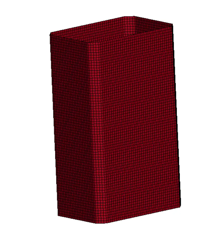
- Modelling a Rigid-wall
Rigid walls are analytical representation of surfaces or volume that are frequently used to represent stiff structure that are either stationary or in motion.
A stationary planar rigid wall is created ahead of the crash box at an approximate distance using the option create entity >> Rigid wall and choosing an appropriate node and plane
A plane is created at that location, but we need to translate it up to some distance far away from the crash box
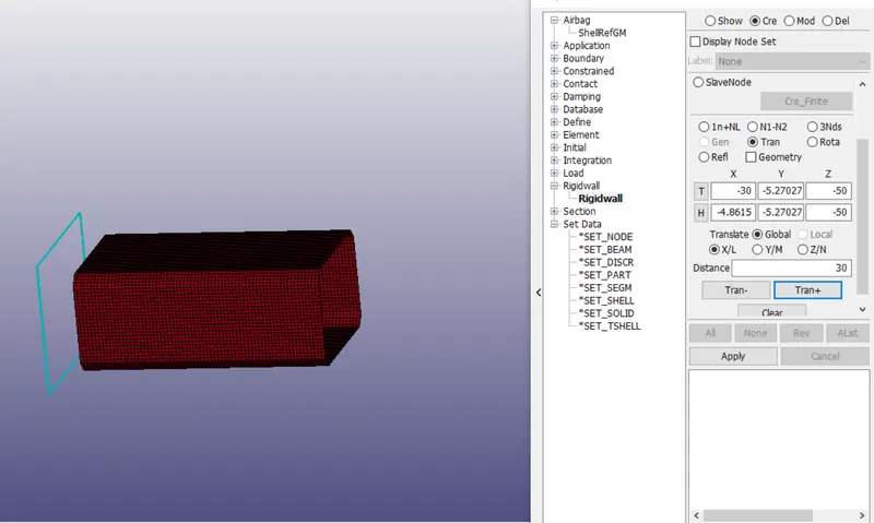
Rigid-Wall Creation
- Assigning Material and Section to the Crash Box part
After creating a rigid wall, the next step is to create the material and section and assign it to the crash box
To create a material, go to Keyword >> MAT >> Choose piecewise material with linear plasticity (MAT_24) and define the property of steel
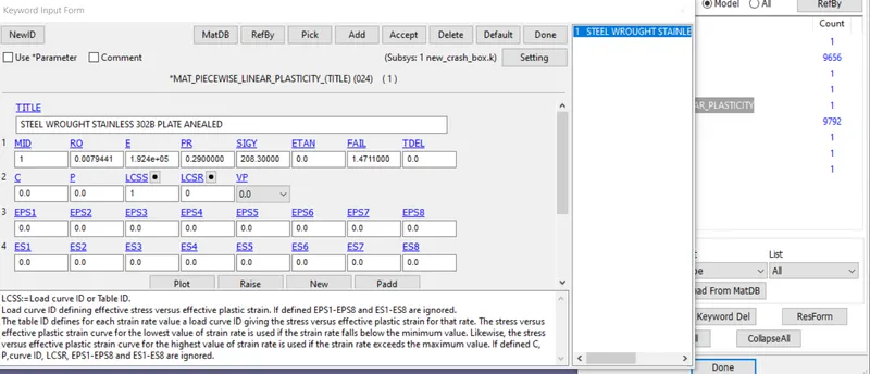
Defining a Material Model for the crash box
There are many material models exist for metals, one of the most robust model is * MAT_024 or *MAT_PIECEWISE_LINEAR_PLASTICITY
This material model is the standard workhorse and is the recommended starting point for elastic -plastic simulation of metals and general plastics, since it is also handled viscoelastic behavior, The crash box is modelled with steel material. There are two ways to define the plastic portion of the curve, either we can use tangent modulus for elastic plastic behavior of steel material, the tangent modulus is useful in describing the behavior of material that have been stressed beyond the elastic region, when a material is plastically deformed there is no longer a linear relationship between stress and strain, by this we can quantifying the “Softening” or “Hardening” of material that generally occurs when it begins to yield. But tangent modulus basically try to approximate the curve, so it is more better if you have actual data of stress strain plot with large number of points
Here we define the non-linear part of stress strain by curve, that is load curve id
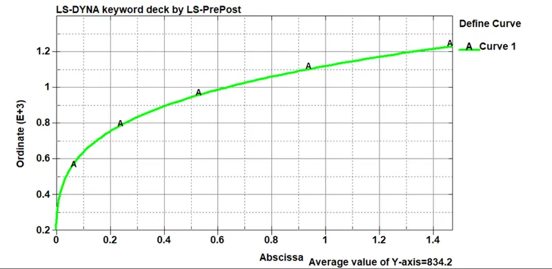
Defining a Non-linear part for the material obtain from uniaxial test
After defining the material, the next step is to create the section, for that go to Keyword >> Section >> Shell Here, we define the element formulation for the shell and define the thickness for the shell which is equal to 1.2mm
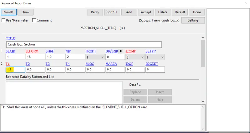
Defining a Section for the crash box part
- After creating the Section and Material now we need to assign it to the crash box part
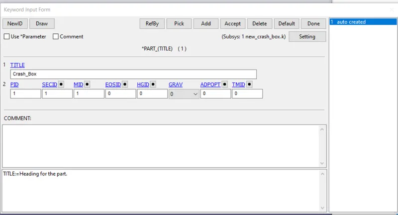
Defining a Section and Material to the Crash box part
- Defining a Contact/ Interface for the Crash Box part
Here we have interaction with rigid wall, so in this case we only need to define Self-Contact that is when the crash box comes in contact with itself, we don’t need to define the contact between the wall and the crash box, so to simply create a contact go to Keyword >> Contact >> Automatic Single surface contact, define the slave id for it, the slave node will be the node of the crash box, create a separate node set for that and assign it to the contact, or either you can directly define the part, it consider all the node as slave node for the contact, so make sure to change the type first to select the slave node by part id option.
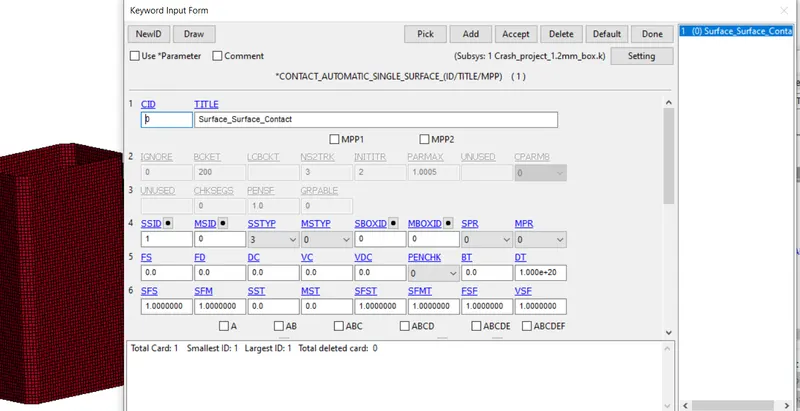
Defining Automatic Surface to surface contact
- Boundary Condition
Now we need to define a boundary condition, means we need to give initial velocity to the crash box, so that it strikes with the rigid wall, so to define the initial velocity go to Keyword >> Initial >> Initial velocity, define the velocity of 13.88 mm/ms in direction to the rigid wall
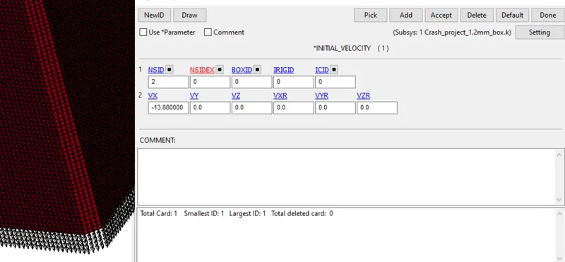
Defining initial velocity to the crash box
- After defining the initial velocity, now the next step is to create the Section at the middle of crash box to get the value of forces along the length of the crash box
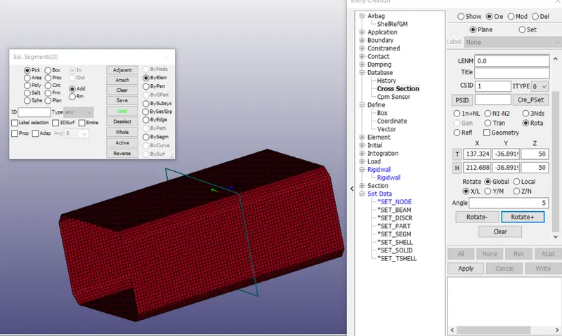
Defining cross-section at the middle of crash box
- Now our initial setup is done, now we need to define the output, for that go to Keyword >> binary d3 plot, this is the main animation file also we need to request the ASCII output as well and in it contains the result of GLSTAT, MATSUM, RCFORC, etc.
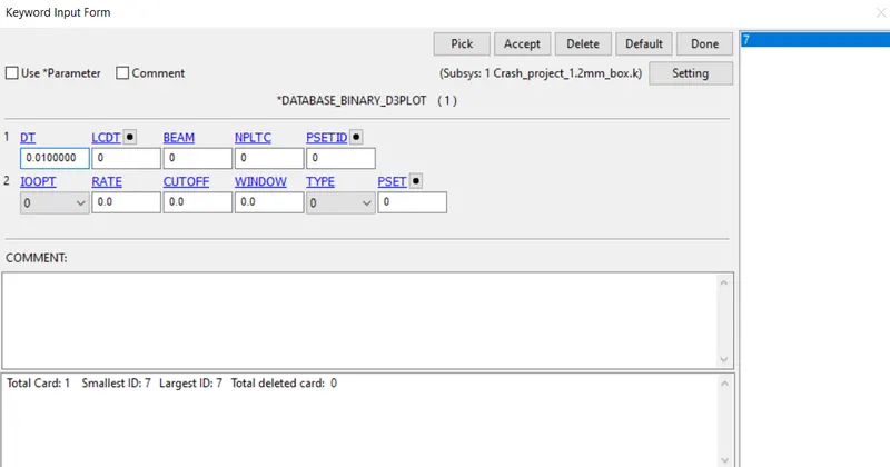
Requesting Binary D3 plot as for output
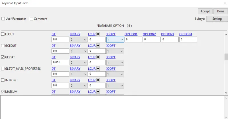
Requesting ASCII as for output
- To run the simulation properly we need to create the control card, without creating control card simulation will not start, and the most important one is termination card, which will define the running time for the simulation. Control Hourglass energy, Accuracy, Energy.
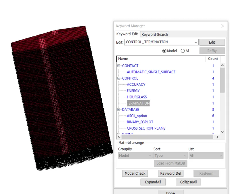
Control Card is created
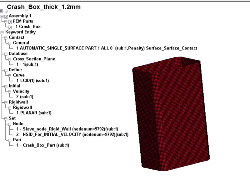
Defining the complete Deck setup for the Drop-Down test
- Now our deck setup is completely, now one thing left is only to check the file, whether there is any error present or not, if present then remove those error before giving them to solve in solver.
- After that we can save the file, but before that one important thing is to check the error before solving the file, if error is present then file is not able to solved by the solver, so make sure to solve all the error and after that save the file,
- After saving the file, the next step is to open the file in Notepad and edit or give the title and add Keyword ID, because it is a general practice and it is recommended, so that file and their result will not mismatch, otherwise if we don’t follow this then there are more chances of mismatch of results, if you do slightly change in the condition and you don’t know which result or d3 plot belong to which, so it is recommended to give them title and Keyword id so that, our result should coming up with proper name.
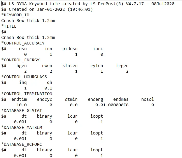
Giving a proper Title and keyword id to file
- Now our file is ready for solving. To solve the file, open the Ls-Dyna Run and import the file here and then run the file for solving, it will show you how much time it take to solve the file, after solving the file it will gives you result in the form of the input we define like main animation file like Binary d3 plot
- Now we got lot of files in the form of result, but our main file is the d3 plot which is a binary file, we can open it in any editor, but this file is not readable, but we have ASCII file which we can open it in notepad, but it is readable, so we again open the LS-Dyna and then open the dyna binary file in it.
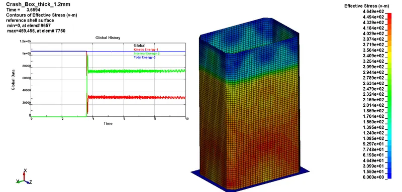
Kinetic energy vs Internal Energy vs Total Energy
As you see here when the crash box comes in contact with the ground the Kinetic energy suddenly drop and it converted in the form of internal energy and further Kinetic energy raised due to movement of crash box and our total energy almost remain constant
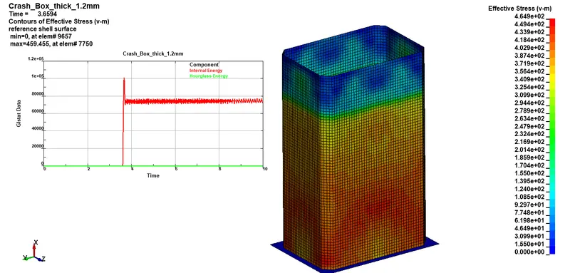
Internal Energy vs Hourglass energy
Here Hourglass energy is almost zero, so there is no such hourglass effect here
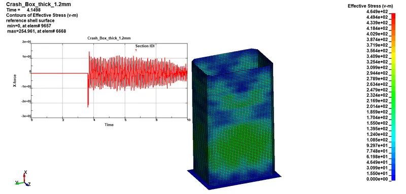
Cross-sectional forces of crash box 1.2mm
X-Directional Stress
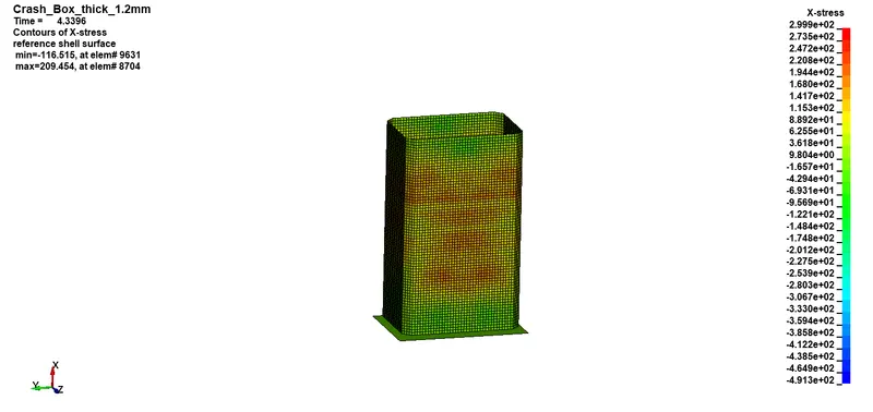
Maximum value of stress in X direction is 299.9 Mpa
Y-Directional Stress
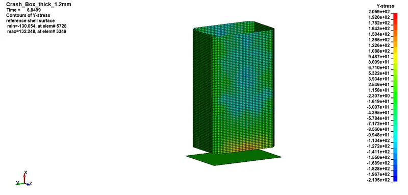
Maximum value of stress in Y-direction is 205.9 Mpa
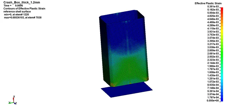
Effective Plastic Strain
Crash Box having 1.5mm thickness
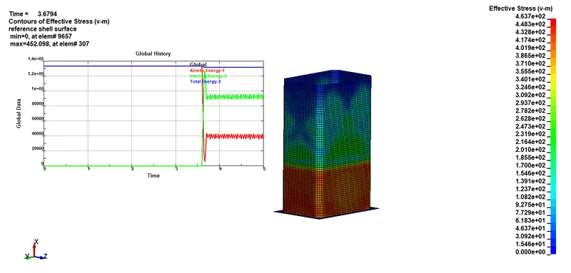
Kinetic energy vs Internal Energy vs Total Energy
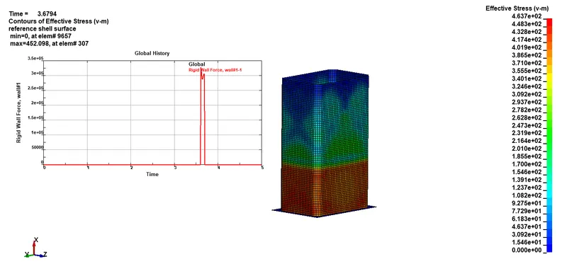
Rigid wall force
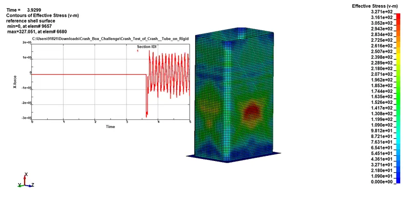
Crash Box 1.5mm cross-sectional forces
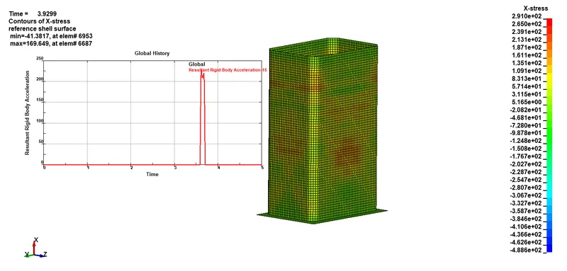
X-Directional Stress
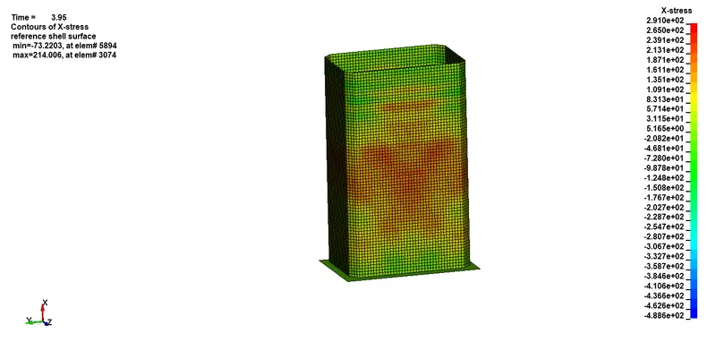
Maximum value of X- Directional stress is 291Mpa
Y-Directional Stress
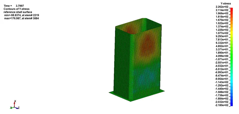
Maximum value of Y- Directional stress is 226 Mpa
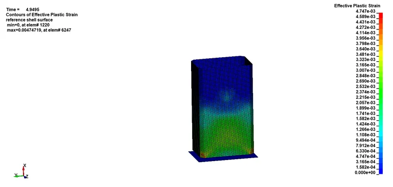
Effective Plastic strain
Resultant rigid body acceleration
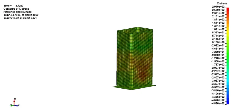
Crash Box Stress in X direction
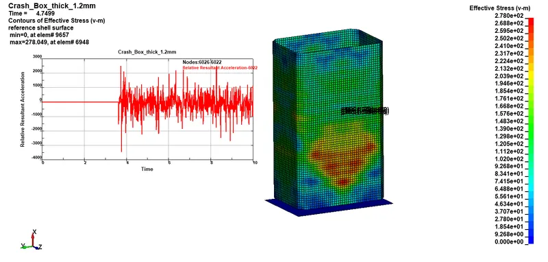
Relative Acceleration of crash box having thickness 1.2mm

Realtive acceleration of crash box having thickness 1.5mm
The following table sumarizes the maximum directional stress of crash box simulation
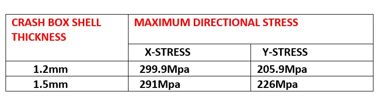
From the above table it is evident that the maximum X directional stress is more for crash box of shell thickness 1.5mm also the Y directional stress is more for crash box having thick 1.5mm
Conclusion:
Crash energy absorbers are important structural elements which play an important role during accidents of automotive vehicles.
A simulation on crash box impacting a rigidwall with 13.88 mm/ms (i.e 50Kmph) velocity. It can be seen from the simulation that the crash box bounces back after hitting the rigid wall.
Buckles and folds in the axial direction so as to come in self-contact
Explicit Approach
Implicit Approach