Week - 4 - Crash Box Simulation
Crash box simulation
Aim :- To perform the crash test for the given crash box with different cases of thickness 1.2 and 1.5 mm onto a rigid wall at speed of 50kmph and derive the requested outputs.
Software Used :- Hypermesh and Ls-Pre-Post V4.7.17
Problem statement :-
In this assignment, the student needs to simulate a crash test for a crash box for which mesh is given. A crash box is a highly energy absorbing structure that crashes on application of loads and reduces impact on other components nearby. A full-fledges crashbox is a highly sophisticated design but in this case we will go with a rectuangular channel which can thought of as the most simple crashbox.
Here are the different assumptions and information required:
- The crashbox should crash into a rigidwall created using *RIGIDWALL_ keyword. Check the manual to understand and create a rigidwall.
- Material for the crashbox is steel. The simulation needs to be started using elastic material to verify its correctness and later a nonlinear material card data will be provided. Thickness of the crashbox is 1.2mm.
- Initial velocity for the crashbox should be around 50 kmph
- The units system to be used is gm-mm-ms
- The simulation should satisfy either of the two situations - (1) It crashes on the rigidwall and rebounces completely or (2) it buckles and folds in the axial direction so as to come in self-contact.
- Once the simulation is completed and results as asked for below is collected, run another simulation by increasing the thickness of the crashbox from 1.2 to 1.5mm.
Deliverables:
- Input .k file and output files (d3plot, glstat, sleout, rcforc)
- Animation of the final simulation
- Cross-sectional force generated in the middle of the crashbox (along its length)
- Acceleration plot of a node in the middle of the crashbox (along its length)
- Maximum directional stress and strain along the length of the crashbox (X strain, Y strain etc)
- Plot of all energies (total, internal, kinetic, hourglass, sliding)
- Compare the accelerations and stress/strain plots of 1.2/1.5mm crashboxes.
Introduction :-
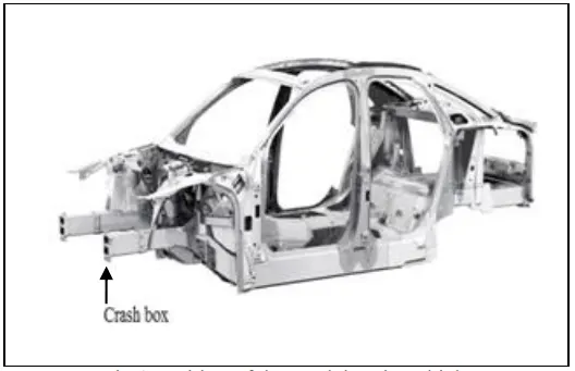
Crush box is mounted on the rear side of the front and rear bumper. Crush box is one of the components in automotive which absorb the crash energy. At the time of impact the crash box will fold like a squeeze box to absorb impact loads and minimize the kinetic energy. In frontal collision the crash box will play a major role to absorb energy by collapsing than the other body parts. It minimizes the damage of bumper, main frame and saved the passengers by major injuries.
Procedure :-
- Import the given model of crashtube in Ls prepost as keyword type.
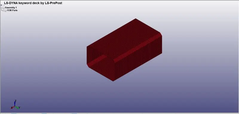
In the opened file, the component (crash box) has meshed with shell elements. The crash box has meshed with 9656 elements/shells and 9792 nodes.
The unit system followed for the unit consistency is gm-mm-ms.
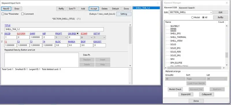
- Create a Shell section card using the Model and Part > Keyword Manager > SECTION > Select the Shell option with Element formulation=2 and thickness = 1.2mm.
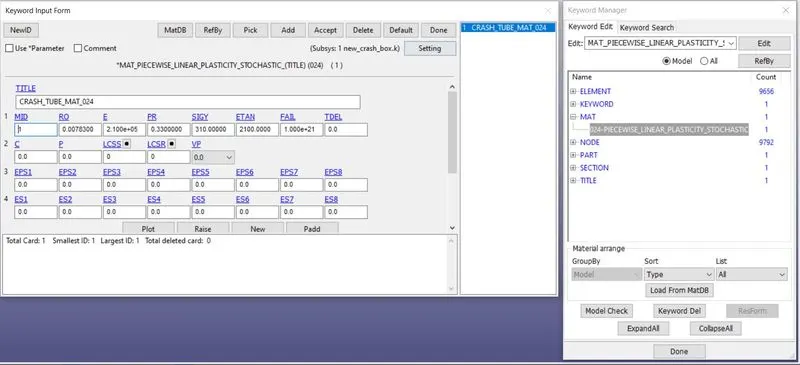
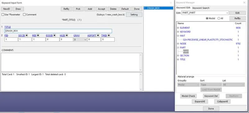
- Define the material for the crash box component. Select the 024-PIECEWISE_LINEAR_PLASTICITY material card for the crash box component.
Model and Part > Keyword Manager > MAT > Select the Material card
Next, define the material properties like mass density, Young’s modulus, Poisson’s ration, Yield point stress value, and other required quantities for the material cards.
- Density= 0.00783 gm/mm3
- Young's modulus=2.10 e+05 gm/mm*ms2
- Poissions ratio=0.33
- Yield strength =310 gm/mm*ms2
- Tangent modulus = 2100 gm/mm*ms2
- Specifying the respective Material and Section ID to the crash box component part IDs.
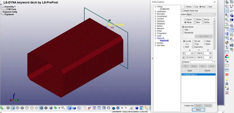
- Create a Rigid wall in front of the crash box 10 mm away by using the *RIGIDWALL_PLANAR card
This is done by selecting Entity Creation > RigidWall > Create. The rigid wall type is selected as a Planar and defined vector with one point and a normal ie, 1n+NL here selected the one node, and the normal is created as a rigid wall. This rigid wall is translated/offset by 10mm from the crash box component.
The black outer line shows the exact location of the rigid wall from the crash box component.
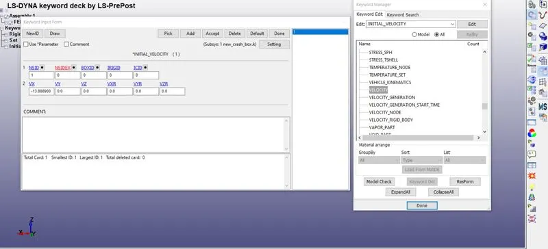
- Next step is to define a velocity of 50kmph (13.8889 mm/ms) and assigned to each node of the selected crash box component, under Entity Creation >Initial>Velocity>Insert the value. The Crash box is selected by pick option with respect to part as shown below.
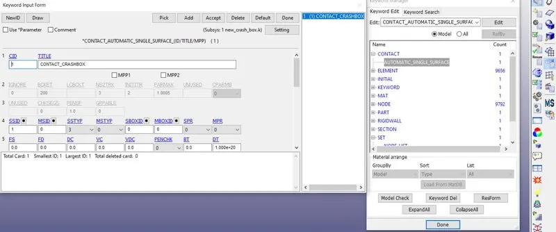
- Create a Contact using Model and Part > Keyword Manager > Contact > Automatic Single Surface. The slave segment type (SSTYP) is defined by the Part ID, here there is no need to define a master surface so only the slave surface definition is sufficient. After the automatic contact was created as the crash box elements are getting self contact during crashing ie, Automatic single surface here it was not needed to define the master surface because the crash box itself is master and slave.
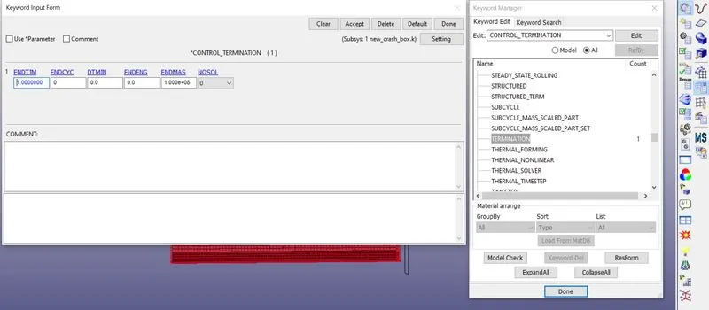
- Next the Termination time is to be assigned by using *CONTROL_TERMINATION card. Here the time to end the simulation can be calculated analytically by using the distance between the rigid wall and crash box component ie,10mm, and the velocity of the crash box ie,13.8889 mm/ms.End time, t = (10mm)/(13.8889 mm/ms) = 0.7199 The calculated time is 0.7199ms but extra time is considered after the impact in simulation ie, the crashing and the bouncing back of the crash box. So, the total time of 1ms is assigned as end time in the *CONTROL_TERMINATION card.
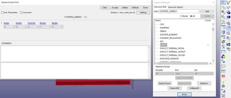
- For calculate the energy dissipation, Hourglass energy, rigid wall energy, sliding interface energy that can be done by *CONTROL_ENERGY card.
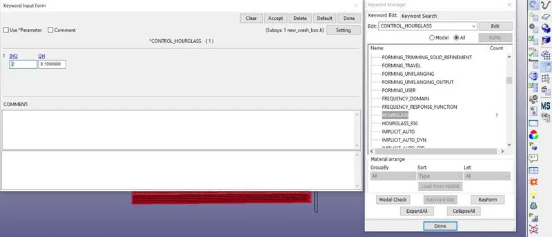
Finally create a *CONTROL_HOURGLASS card for control hourglass effect in the analysis with 1HQ=2, QH=0.1.
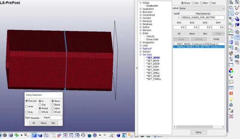
- Creating Set data of nodes and elements for calculating Cross-sectional force generated in the middle of the crashbox (along its length) and Acceleration plot of a node in the middle of the crashbox (along its length)
- A set of nodes an elements are created at the middle part of the crash box in order to find out the cross sectional force (SECFORCE), Acceleration of the node etc at the middle part along its length.
- These sets can be created using Create entity> Set Data. Similarly create set for shell elements by using *set_shell option.
- Now, the following output data is generated by using the *DATABASE card with a time step of 0.01ms are assigned for generating output data.
DATABASE_BINARY_D3PLOT --> Used to find out the animation of the process,
DATABASE_ASCII_NODOUT --> To find the Nodal motions,
DATABASE_ASCII_ELOUT --> To find the element data,
DATABASE_ASCII_GLSTAT --> To find the global statistics and energies,
DATABASE_ASCII_MATSUM --> To find the material energies,
DATABASE_ASCII_RCFORC --> To find the Resultant contact interface forces,
DATABASE_ASCII_SLEOUT --> To find the Contact interface energies
DATABASE_ASCII_SECFORC --> To find the Cross-section forces data
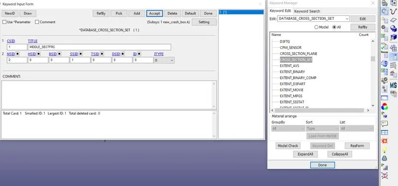
*DATABASE_CROSS_SECTION_SET card is used so as get nodes and element/shell set from the component and are assigned for node-set ID (NSID) and shell element set ID (SSID) respectively.
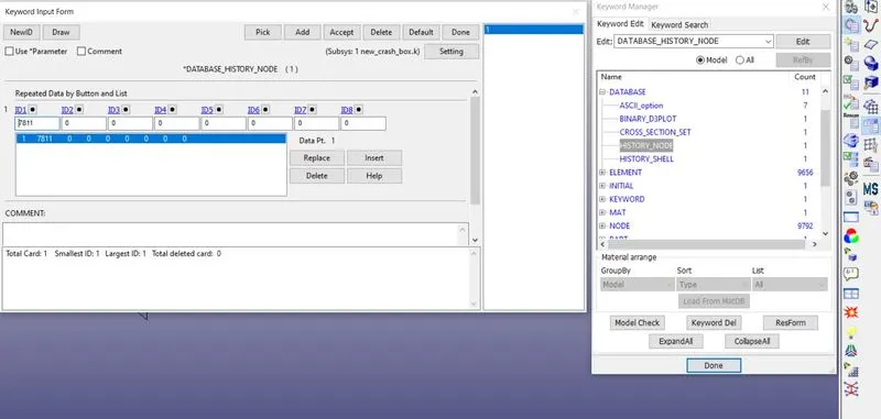
- The acceleration plot of a node and element of the crash box can be done by picking the desired node and element by using *DATABASE_HISTORY_NODE and *DATABASE_HISTORY_SHELL card.
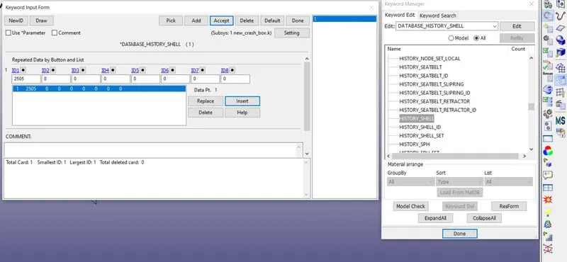
- After assigning all the above-mentioned keywords, the model is ready for the simulation. The keyword file (.k) can be edited in notepad++ so that the comparison study can be done for the part which is having 1.2mm and 1.5mm thickness. Save the keyword for both files and open in the LS-DYNA manager which solves the problem with normal termination.
Output results :-
- The cross-sectional force generated in the middle of the crash box:
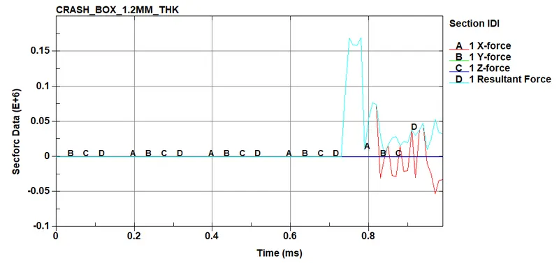
Plot :- Section Force of 1.2mm Thickness crash-box
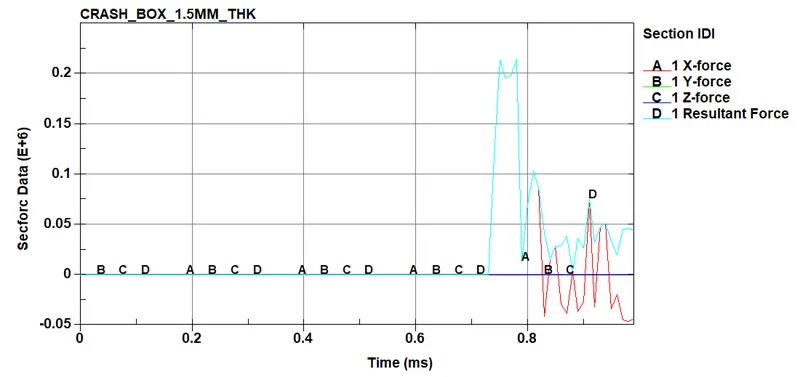
Plot :- Section Force of 1.5mm Thickness crash-box
From the above graphs we can able to see that the force value at the Y and Z direction after impact is very low since the velocity value is along the X-direction. At the impact time, we can see that the force value in X-direction peaks up and goes down after bounce-back of the crash box. The Resultant force of a 1.5 mm thickness crash box is higher than that of a 1.2 mm thickness crash box since it absorbing more internal energy which is differenciate in below plots.
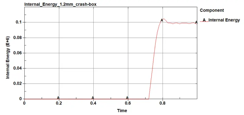
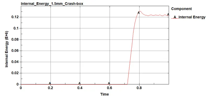
- Strain plots for the crash box:
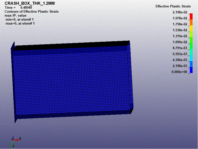
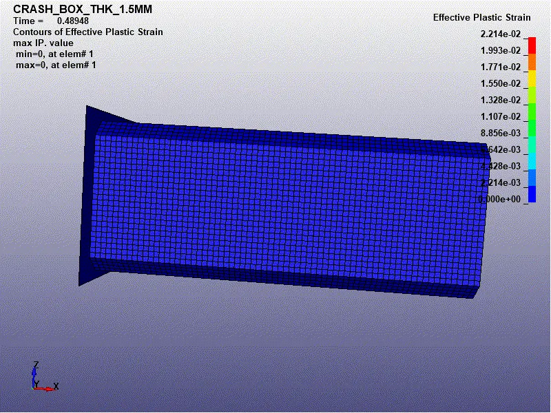
The maximum effective plastic strain is in 1.5mm thickness crash-box which is 2.214e-02mm and in 1.2mm thickness crash-box is 2.198e-02mm because as per Newton's second law we know that F=ma, here 1.5 mm thickness crash box is having higher mass compared to the 1.2 mm thickness crash box.
- Stress plots for the crash box:
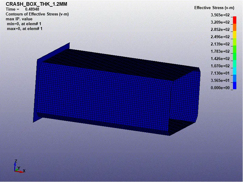
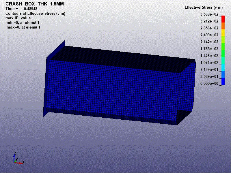
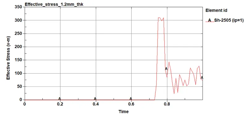
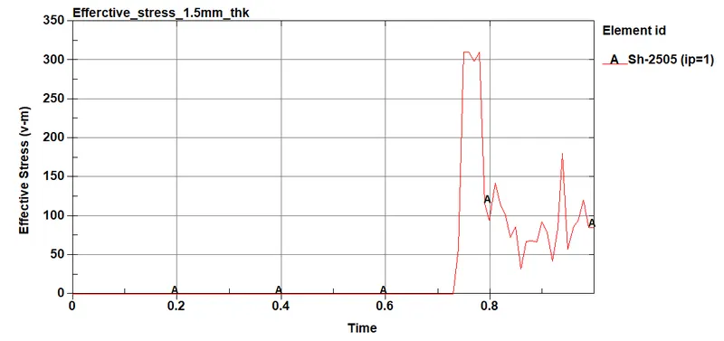
From the above simulations we can able to see the Effective Stress(v-m) for 1.2 mm and 1.5 mm shell thickness crash box. Here we have taken Element no 2505 from 1.2mm thickness crash box and Element no: 2505 from 1.5mm thickness crash box. The value of stress in the particular elements that we took for study exceeds the yield strength = 310 gm/mm*ms2 and so there will be permanent deformation in the crash box.
Here in the 1.5 mm shell thickness crash box, we can see the lesser value of stress generation than the 1.2 mm shell thickness crash box since here more resisting area to the impact/load.
- Acceleration plot of a node in the middle of the crash box:
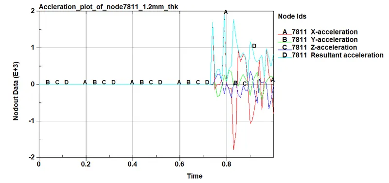
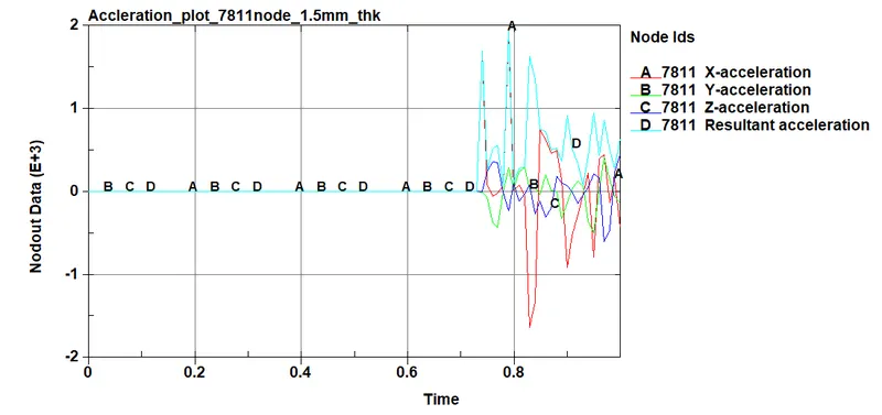
From the above plots we can able to see that the nodal acceleration in the X-direction is negative since the accelerated body when came to impact there a deceleration happened. Here the value of deceleration in X-direction is nearly the same and the resultant acceleration is a magnitude and doesn't depend on the direction so we can see the positive value and almost equals the value of X-direction magnitude since the acceleration value in the Y and Z direction is very small.
- Energy plots for the crash box (total, internal, kinetic, hourglass, sliding):
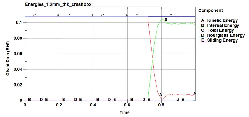
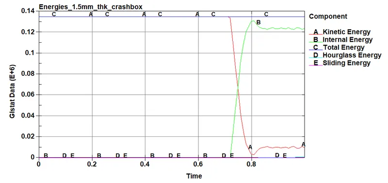
From the above plots we can able to see that the 1.5mm thickness crash box is having higher momentum (ie, p =mv) and higher energies compared to the 1.2 mm thickness crash box. Here the velocity and acceleration are the same at the initial time but the mass value is different.
Initially, the crash box is having kinetic energy (ie, K.E = 1/2mv2) but after the impact, we can able to see that the kinetic energy is converted to internal energy. Hereafter nearly t=0.8ms that impact we can see that the crash box bounces and gains small velocity is gained that is shown in the graph above plots
we can find out that hourglass energy is nearly zero since we had considered the control keyword for the hourglass problem and within the control.
Here the contact keyword is only mentioned as the Automatic_single_surface for the crash box so the force due to contact will not be recorded and if you see the DATABASE_ASCII_RCFORC and the DATABASE_ASCII_SLEOUT will not return any value as plot since the rigid wall part is undefined ie, the master part ID. So we see the value of Sliding energy as zero in the graph.
Here the total energy of the system remains constant since there is no energy loss/gain in the system but there will be small deformation since we took the MAT_24 material property and it will be very small in value.
Conclusion :-
Thus, the crash-box simulation is performed as per boundary conditions mentioned in problem statement with all required outputs.