Week 4 - CHT Analysis on Exhaust port
CONJUGATE HEAT TRANSFER SIMULATION IN EXHAUST PORT USING ANSYS FLUENT
AIM
- To give a brief description of why and where a CHT analysis is used.
- To give the significance of the y+ value according to the turbulence model.
- To calculate the wall heat transfer coefficient on the internal solid surface & show the velocity & temperature contours in appropriate areas.
- To determine and verify the accuracy of HTC and the factors depending on the accuracy of prediction from the simulations.
INTRODUCTION
The conventional way of heat transfer analysis through isothermal or constant heatflux boundary conditions do not give accurate predictions in real life coupled heat transfer situations. The coupled solution of governing equations in the fluid and solid domain is required to obtain realistic values of temperature distribution and heat load on the solid surface. Earlier
analytical CHT studies were mainly based on differentassumptions. Due to such assumptions in obtaining the solutions, most of the earlier analytical results are not applicable for complex CHT problems. Moreover almost all the analytical works in this field are two dimensional laminar studies. Tremendous development of computational fluid dynamics and numerical heat transfer occurred in the last two decades widened the scope of CHT analysis. With the aid of fast and efficient computers many researchers have extended their CHT Studies to more complex CHT problems.
The CHT studies are extensively used in Numerical Analysis of Natural Convection and Radiation Heat Transfer from Various
Shaped Thin Fin-Arrays,in cooling techniques,Investigations About Coupling Techniques for CHT Solvers,Studies Related to Aero-Thermal-Structural Interactions in High Speed Flows,Thermal Treatment of Materials ect.Most promising application of CHT study is found to be convective cooling of mechanical, electrical and electronic components. Substantial number of CHT studies in the field of turbine blade cooling, electronic circuit cooling and alternator winding cooling are available. CHT technique also got application in sensor design, heat exchanger analysis, space vehicle design and even analysis of biosystems. The coupling of CHT codes with structural solvers extends the application envelope of CHT technique.
THEORY
The exhaust port represents the interface between the internal combustion engine cylinder and the exhaust manifold followed by the turbocharger. Hence, the available energy after combustion shall be transmitted from the cylinder
to the turbocharger inducing minimal losses. Nonetheless, the efficiency of the turbocharger turbine is sensitive to the flow conditions at the inlet. Thus, the exhaust port should not only be designed with the intention to minimize losses, moreover the effectiveness of the generated flow structures transmitted to the turbocharger turbine should be considered. The energy content associated with these structures and their behavior may influence the engine efficiency potentially higher than
the flow losses in the port itself.
The accurate calculation of convective heat transfer coefficient requires boundary condition consists of the coupling of solid and fluidfields. Such a boundary condition assumes that the heat convected in or out to or from the solid is absorbed from or rejected to the fluid passing over the solid surface.To have analytical or numerical prediction of heat transfer coefficient close to experimentally obtained values requires focus on conjugating the boundary condition at the fluid–solid interface
through coupled heat transfer analysis. Such a coupled field study is termed as Conjugate Heat Transfer (CHT) analysis.
The CHT analysis is essential in a situation where solution domain consists of more than one sub-domains in which heat transfer is governed by different differential equations. In such a case suitable governing equations are to be solved in the respective sub-domains and these solutions need to be conjugated at the interfaces of sub-domains.
The heat transfer problem is used to design the exhaust port material and to predict accurately the efficiency of the turbocharger, catalytic converters, thermal reactors, and after treatment devices.The flow in the exhaust port is dominated by the large scale turbulent flow structures and not by the wall shear generated turbulence.These large, energy containing structures and their behavior influence the heat transfer. The transient heat transfer is primarily affected by the gas temperatures in the cylinder rather than the cylinder wall temperatures.
SOLVING AND MODELLING APPROACH
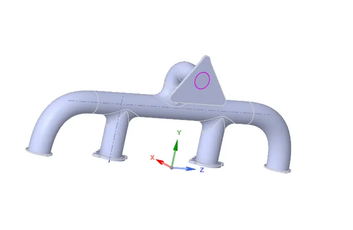
The below geometry of exhaust port with 4 inlets and 1 outlet is used to simulate the process of exchanging heat as the flow occurs. We assume that the inlet fluid is hot which heats the pipe. On external surface the heat transfer coefficient is present which depends on the reynolds number.
The fluid volume is extracted and the geometry is seperated to fluid volume and solid volume for convinience. The share topology function is enabled so that the 2 components share the heat transfer smoothly and to ensure continuity(no physical gap) in the mesh between 2 seperate components.
For the conservation of the fluid momentum
at time t, the Navier-Stokes equations in the three dimensions xi, i ∈ {1, 2, 3} are solved,
`∂(ρui)/ ∂t + ∂(ρuiuj) /∂xj = − ∂ps /∂xi + ∂σi j/ ∂xj ,`
where ρ is the fluid density, u is velocity, ps is static pressure, and σ is the viscous stress tensor.
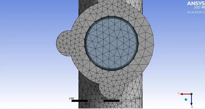
A conformal mesh with the convection boundary conditions is used for meshing.The outer wall,inlets and outlets are named and all those which are not named falls to adiabatic condition by default.The refined mesh cell count is 238815 and the element quality is 18 percent. The element size is reduced to 10mm for more refined mesh within the liscence.
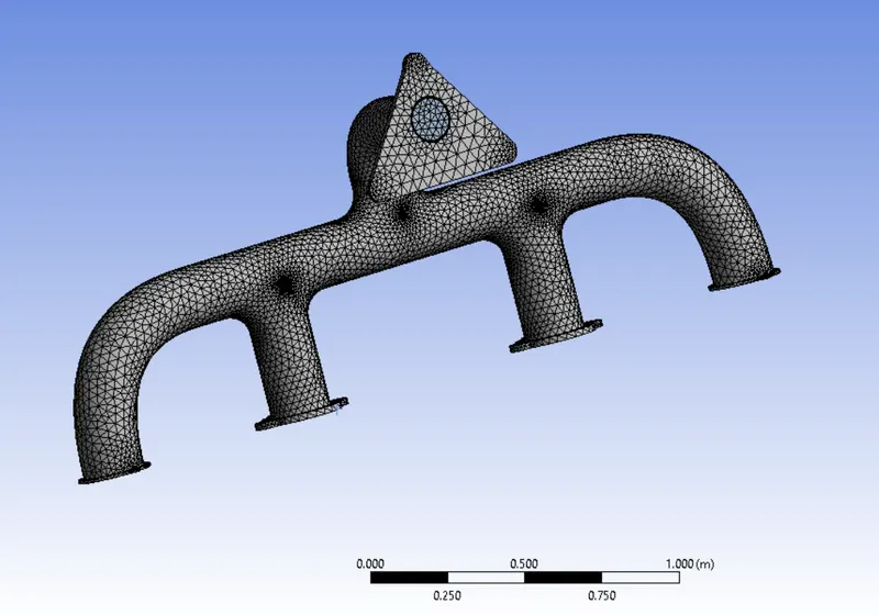
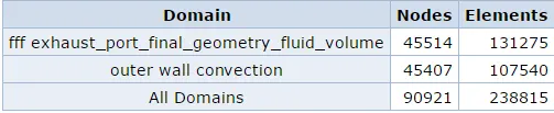
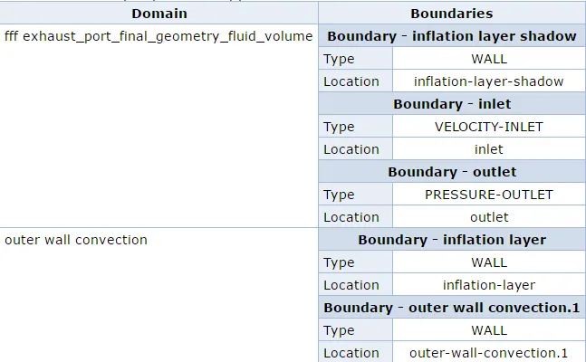
The refined mesh consider more details like the inflation layer. The Y plus value is maintained between 0-5 which corresponds to very high reynolds number. The inlet velocity is 5m/s and the wall spacing is 0.000125^3m. The reynolds number is R=273834.804
SOLVER SETTING
A pressure based steady state simulation is run. The boundary condition of inlet velocity is set to 5m/s with temperature 700K. The thermal condition is set to convection with heat transfer of 20W/m^2 K.Hybrid initialization with 150 iterations are done to get the temperature and velocity contours.
RESULTS
The static temperature contours are obtained for the exhaust port. The temperature,velocity,heat tranfer is found at the throat of the pipe. The total pressure losses over the exhaust port is divided into sections.
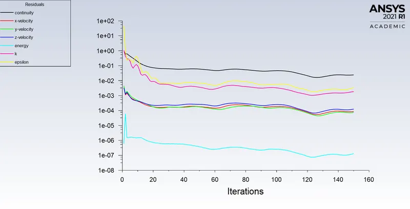
1.Residuals from the simulations
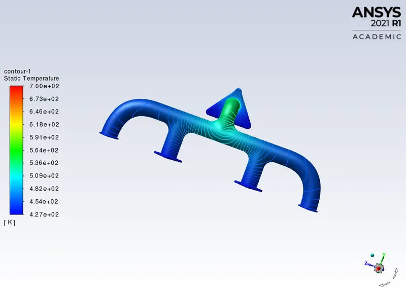
2.a.Temperature contours from non refined mesh of exhaust port
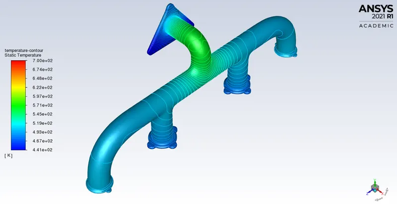
2.b. Temperature contours from refined mesh of exhaust port
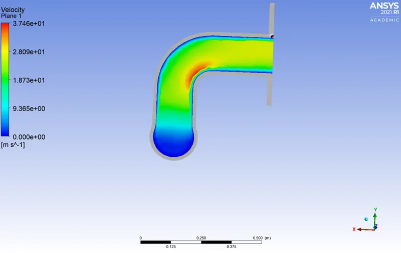
3.a.Velocity contour at the throat of non refined exhaust port
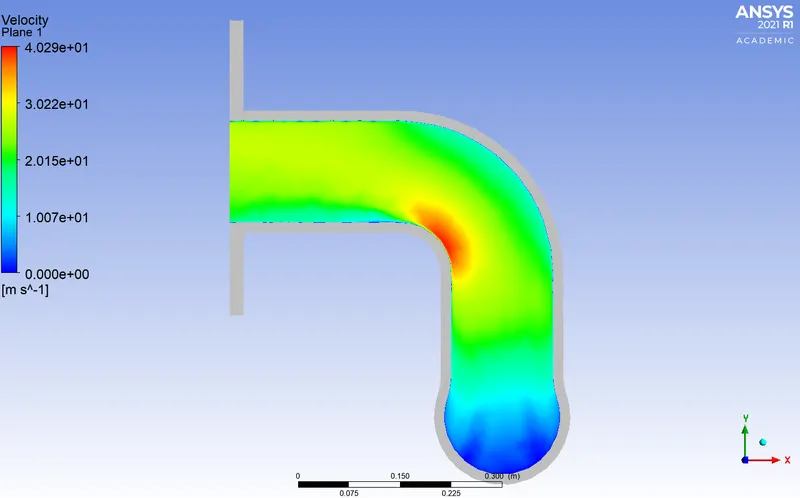
3.b. Velocity contour at the throat of refined exhaust port
The maximum heat transfer from fluid to solid takes place at the higher temperature which is in the middle of the figure towards the lower wall.
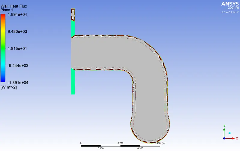
4.Heat transfer flux in refined exhaust port throat.
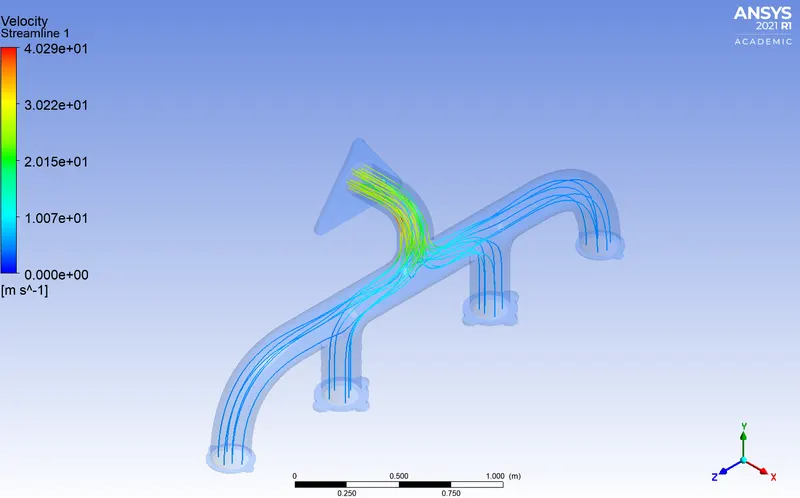
5.Velocity Stremlines starting from inlets with a velocity of 25m/s.
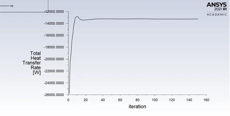
6. Heat transfer rate graph

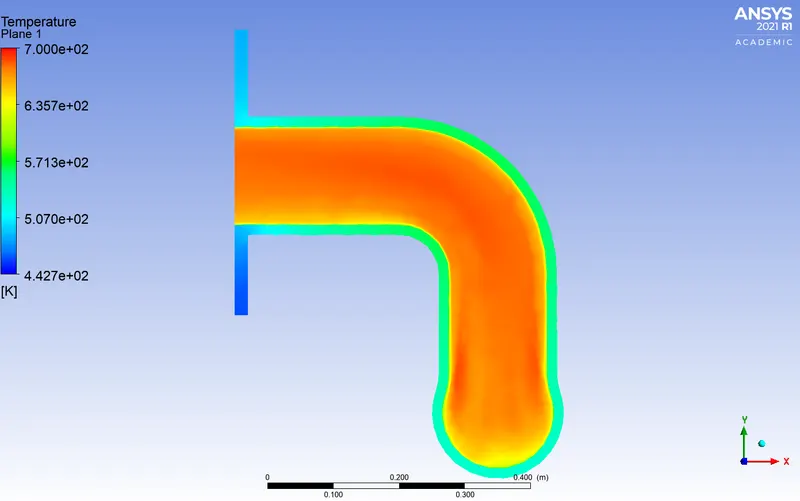
The outlet has higher relative velocity because of mass conservation. At the outlet, higher velocity corresponds to higher reynolds number and thus higher heat transfer from fluid to solid.
CONCLUSION
- The velocity contour at the throat of the exhaust port and the velocity streamlines show that the velocity of the flow is increased at the middle of the throat towards the lower wall. This is in agreement with mass conservation.
- The exhaust port losses heat towards the outlet of the throat since the heat transfer coefficient is dependent on the Reynolds number. Hence the temperature decreases abruptly towards the outer throat. The negetive sign of heat transfer indicated that the heat is lost.
- According to newtons law of cooling,wall heat transfer coefficient = wall heat flux /(wall temperature- wall adjecent temperature or bulk temperature), then the heat transfer coefiicient is hight at the middle of the throat at the lower wall due to high velocity in that region.The heat transfer rate is -12598W and the average temperature at outlet is 780K, Area weighted average of temperature =511 K, wall temperature at the throat =776K.