Week 4 - CHT Analysis on Exhaust port
CHT ANALYSIS ON EXHAUST PORT
AIM: To simulate Conjugate Heat Transfer Analysis on the Exhaust port by using Ansys.
OBJECTIVE:
- Give a brief description of why and where a CHT analysis is used.
- Maintain the y+ value according to the turbulence model and justify the results.
- Calculate the wall/surface heat transfer coefficient on the internal solid surface & show the velocity & temperature contours in appropriate areas.
- How would you verify if the HTC predictions from the simulations are right? On what factors does the accuracy of the prediction depend?
THEORY
Conjugate Heat Transfer:
WHAT?
Conjugate Heat Transfer (CHT) refers to the coupling of conduction in solids with the convective and radiative heat transfer in the surrounding fluids. In other words, CHT corresponds with the combination of heat transfer in solids and heat transfer in fluids. In solids, conduction often dominates whereas, in fluids, convection usually dominates. Efficiently combining heat transfer in fluids and solids is the key to designing effective heaters, coolers, or heat exchangers. Heat transfer in solids and heat transfer in fluids are combined in the majority of applications. This is because fluids flow around the solids, or between solid walls, and because solids are usually immersed in a fluid.
WHY?
- Understanding of the complex heat transfer mechanisms and the interactions between those mechanisms to improve the performance and increase the lifespan of the components to be analyzed.
- Conjugate Heat Transfer analysis provides the temperature distribution in solids and fluids, and clear insight on velocity distribution and mechanism of heat transfer of fluid, like in engines.
- It is more accurate and fast to simulate the problem.
- Can be used in complex scenarios like in automotive components or in power plant components.
- Multiple numbers of regions can be simulated.
- All types of region combinations can be simulated like solid-fluid,fluid-fluid, etc.
WHERE?
- Analysis of Heat transfer mechanism in the turbocharger.
- HVAC systems
- Burners, combusters, electronic devices.
- Automotive, power plants, and various other applications.
- Heat transfer in ribbed passages
- Heat transfer in micro-channels
- Heat transfer in fin arrays
- Heat transfer in mobile phones
- Drying of a porous flat plate
How would you verify if the HTC predictions from the simulations are right? On what factors does the accuracy of the prediction depend?
Nusselt's number is given by:-
`h= (Nu*K)/L`
where h= Heat Transfer Coefficient
Nu= Nusselt's Number Nu = 0.023Re Pr ( Pr is the Prandtl number)
K= Thermal conductivity coefficient
L= Characteristic Length
Where Pr = (CP* μ)/k
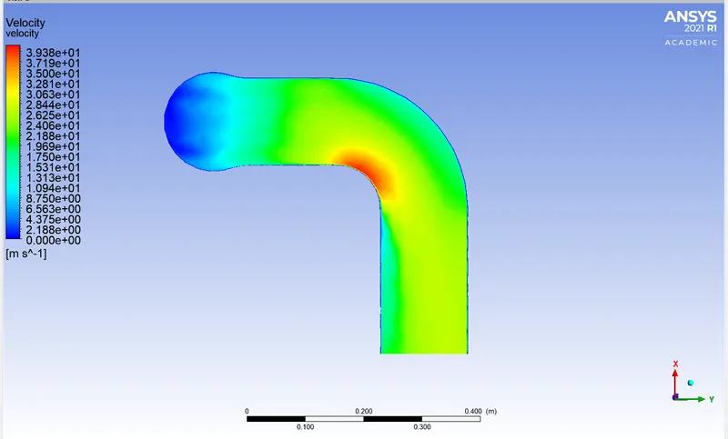
We know that Nusselt's number is a function of Reynold's number, which in turn is a function of flow velocity. Therefore, HTC is directly proportional to flow velocity. We can see from the images above that both the HTC and velocity are maximum near the outlet. Hence, the HTC predictions from the simulations are correct.
Factors affecting the prediction are as follows:-
- Element Size and Quality = The finer the mesh, the accurate the results.
- Inflation Layer = It increases the quality of mesh near the boundary interface and helps to capture smooth plots of different quantities.
- Mesh at the solid-fluid interface = The mesh at the solid-fluid interface must be conformal.
SOLUTION AND RESULTS
In this project, we discuss the CHT analysis of the exhaust port by the following steps
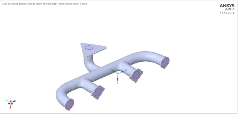
GEOMETRY
- Our base geometry is given, to which we change it according to our requirements.
- First, we check for any duplicate edges and clear them.
- Then we extract the fluid volume by the volume extract option.
- Renaming and moving them to a single head 'final geometry'
- then we enable the sharing and share the topology which is used for a perfect intersection between solid volume and fluid volume.
The Second step
MESHING
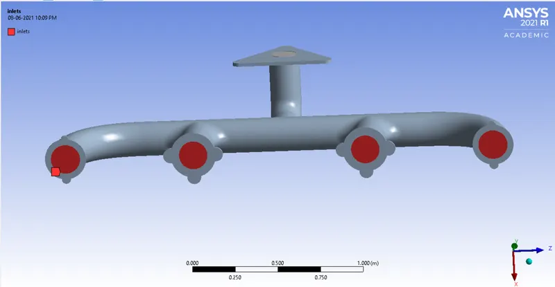
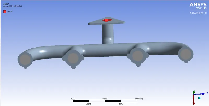
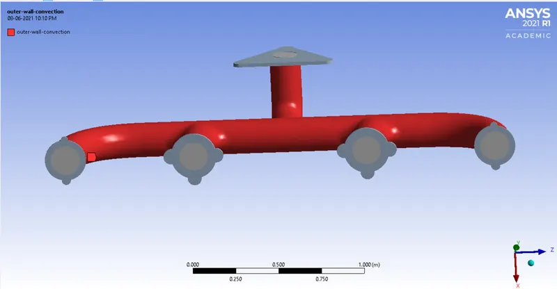
- We start the meshing by naming all the outer surfaces, inlets, outlet, outer-wall-convection, and the inflation layer.
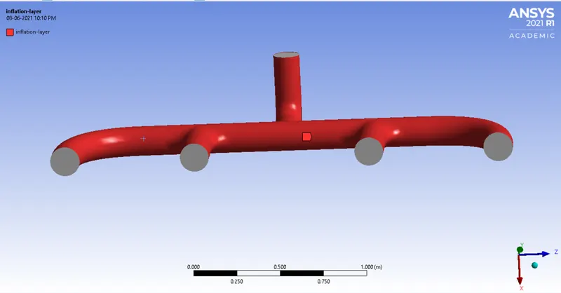
- Then we use body sizing for the solid part and reduce the size to 0.005
- Then for the inflation layer, we select the named selection 'inflation-layer' and the total thickness of 0.005 mm for 5 layers and a 1.2 growth rate, activating the mesh through curvature
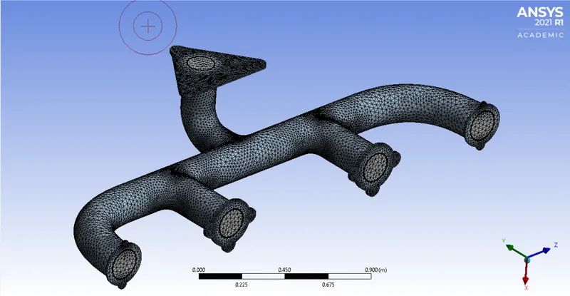
The final mesh with a 373281 number of elements and 112638 number of nodes.
Moving on to the next step
SETUP AND RESULTS
|
SETUP |
||
|
Solver Type |
Pressure-Based |
|
|
Velocity Formulation |
Absolute |
|
|
Time |
|
|
|
Viscous Model |
K-epsilon | |
|
Material |
Fluid type: Air Solid-type: Aluminium |
|
|
Cell zones |
Fluid type: Air | |
|
Boundaries |
Inlet (velocity inlet) Velocity Magnitude 5m/s Temperature – 700K Outlet x (Pressure outlet) Gauge Pressure – 0 pas. Outer-wall-convection -Wall with the thermal condition being convection and heat transfer coefficient All other walls - adiabatic |
|
|
Reference values |
Area = 1 Density = 1.225 Enthalpy = 0 Pressure = 0 Temperature = 700K Velocity = 5m/s Viscoity = 1.7894e-05 |
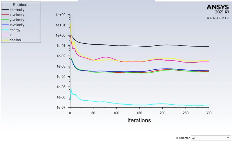
After running the simulations for 300 iterations
The Residual Plot:
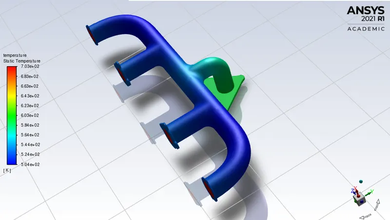
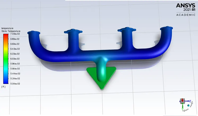
Temperature Contour from the simulation:
Then from the post-processing
Velocity Contour:
Temperature Contour: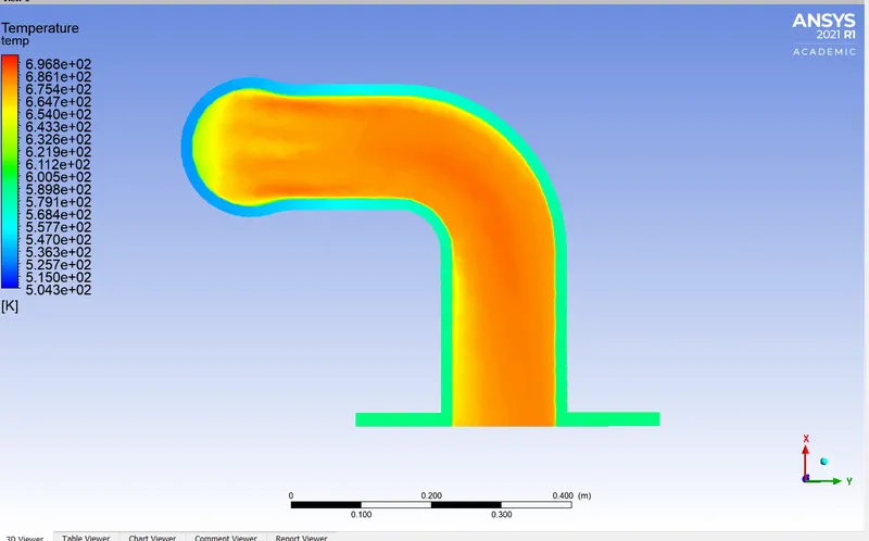
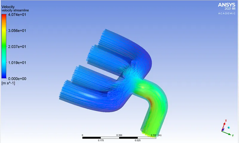
The streamlines through the outer-convection-wall
And the Wall Heat Transfer Coefficient
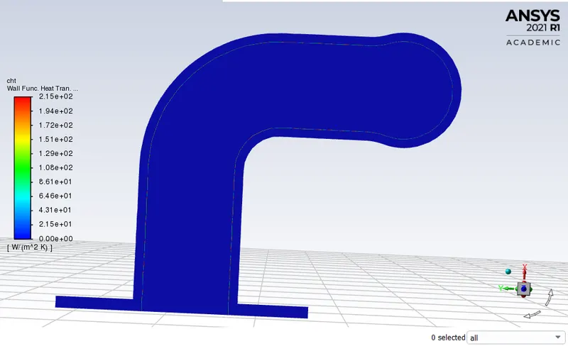
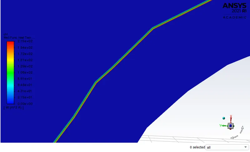
This is the view of the interior layer of solid volume
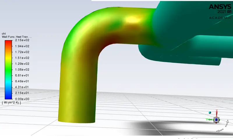
Describing the wall function heat transfer coefficient creating a plane in z-axis.
CONCLUSION
- Increasing the refinement and adding inflation layers to the mesh increases the accuracy of the results.
-
Two factors influence the performance simultaneously: one being Flow is developing along the length and the heat transfer coefficients tend to decrease along with the flow and two being Turbulence.
-
At the same time, turbulence is developing with tube rows at the bent, which would increase heat transfer coefficients.
-
The maximum heat transfer results at the Bent of exit port, It is because to ensure the conservation of mass at exit port velocity should more, which results in higher velocity and increase in velocity attain a Reynolds number that is sufficient to make flow turbulent and higher Nusselt number at pipe bent at the exit, which increses Heat transfer co-efficient at that location.