Week 4 - CHT Analysis on Exhaust port
CHT ANNALYSIS OF EXHAUST PORT
AIM-To check the CHT analysis of the exhaust port used in the engines
OBJECTIVE
The objective of the simulation is to analyse
*Simulation of Conjugate heat transfer on exhaust manifold in the required cut sections
*Calculation of wall heat transfer coefficient on internal solid surface on the inlet outlet and the curves present on the ports
*Maintaining appropriate y+ value for the turbulence model
The Conjugate Heat Transfer (CHT) analysis type allows for the simulation of heat transfer between solid and fluid domains by exchanging thermal energy at the interference between them. A typical application of this analysis type exists as but is not limited to the simulation of heat exchangers, cooling of electronic equipment, and general-purpose cooling and heating systems.
The contemporary conjugate convective heat transfer model was developed after computers came into wide use in order to substitute the empirical relations of proportionality of heat flux to temperature difference with heat transfer coefficient which was the only tool in theoretical heat convection since the times of Newton. This model based on a strictly mathematically stated problem describes the heat transfer between a body and fluid flowing over or inside it as a result of the interaction of two objects. The physical processes and solutions of the governing equations are considered separately for each object in two subdomains. Matching conditions for these solutions at the interface provide the distributions of temperature and heat flux along with the body flow interface, eliminating the need for a heat transfer coefficient.
Why CHT analysis is used:
CFD and more specifically CHT analysis can accurately predict heat transfer by simultaneously solving all the relevant solid and flow field heat transfer processes, for e.g, conduction through solids, free and forced convection in the gases/fluids, and thermal radiation.
The CHT approach has an advantage over Finite element thermal analysis in that wall heat transfer coefficients and their local variations on surfaces are directly calculated within the model rather than based on simplified empirical calculations. The CHT approach, therefore, has benefits for these applications where heat transfer is either non-uniform or difficult to calculate empirically.
Where is CHT analysis used:
Starting from simple examples in the 1960s, the CHT method has become a more powerful tool for modelling and investigating natural phenomenon and engineering systems in different areas ranging from aerospace and nuclear reactions to thermal goods treatment and food processing, from the complex procedure in medicine to atmosphere/ocean thermal interaction in metrology, and from relatively simple units to multistage, nonlinear processes.
STEPS FOR THE ANNALYSIS
- 1.Geometry
- 2.Meshing
- 3.Setup
- 4.Solution
- 5.Results and analysis
GEOMETRY
*For this assessment we are using the exhaust valve setup of a 4 cylinder engine which was downloaded for the assessment.
*design will be analysed for any duplicate surface by using extra edges to remove the duplicate surface .
*after the edges are repaired we will then develop internal volume for the fluid by using volume extract command
*after that we will name the new volume and shift the two volumes to a new volume and name it final volume
*We will then merge both the volumes together and give share topology to the volumes followed which we will go to MESHING
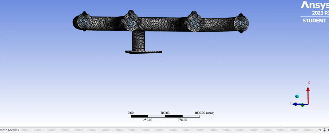
- we will name the inlet and outlet and outervolume of the exhaust valve
- we will generate mesh with element size of 50mm
- we will save the mesh and move to setup
SETUP
-
- Equation used-K-epsilon
- medium of fluid=air
- medium of solid=aluminium
- inlet velocity =10 m/s
- inlet temperature=700 K
- steady state pressure based solve with hybrid initialization is used
- outer surface has conductive heat transfer with thermal conductivity of 20
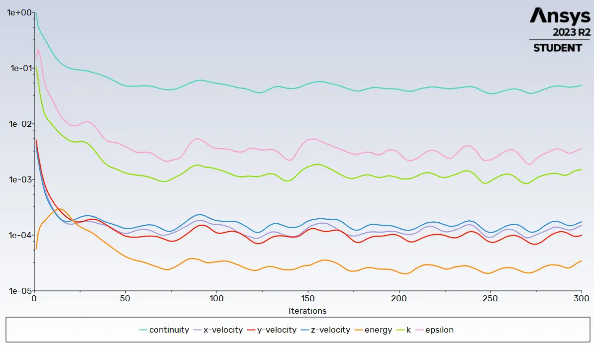
- Based on the results 300 iteration was generated
RESULTS
Velocity
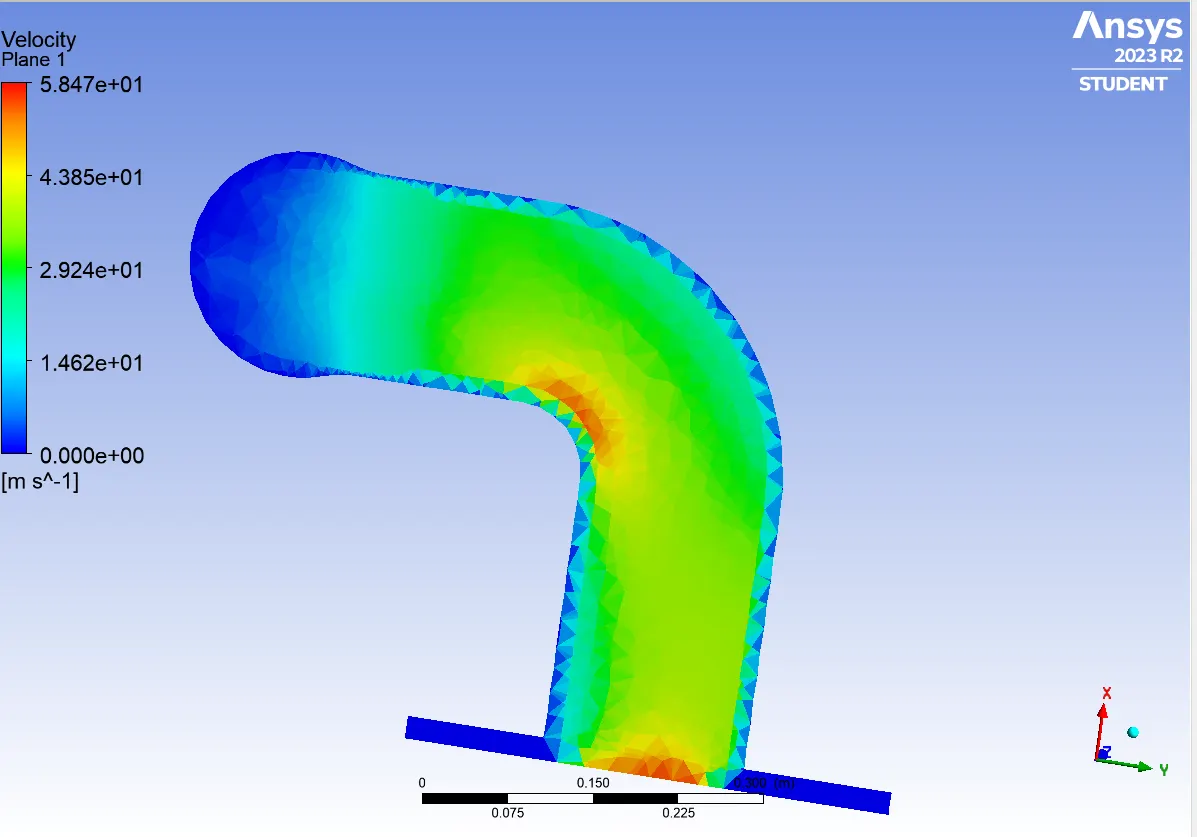
maximum velocity =58.4729 at outlet and the curve
Temperature
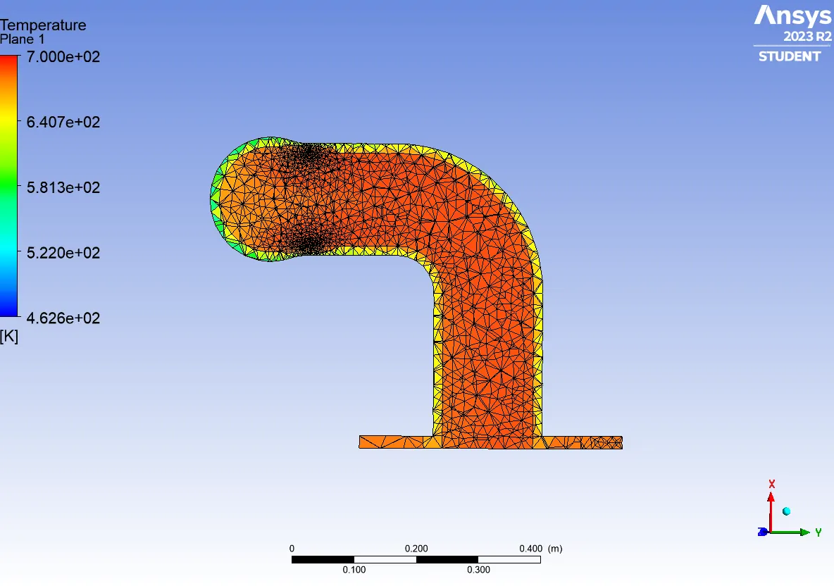
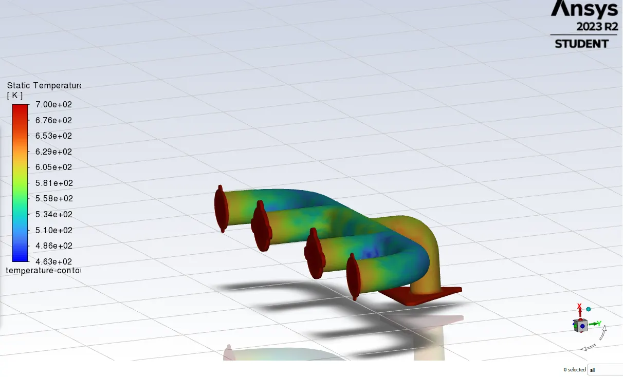
Wall adjacent tempreture max is 693.229 K at the curve near the exhaust
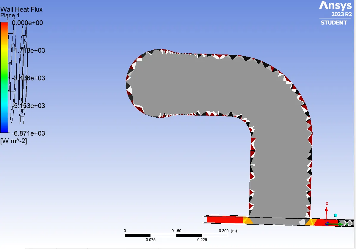
Wall heat flux is maximum 6871.15 W/m^2 at the cuve near the outlet 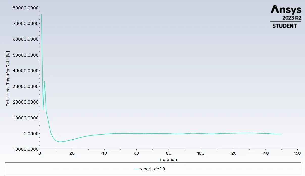
Heat transfer rate=338 W
CONCLUSION
According to Bernoulli's mass conservation principle mass is conserved in our model which is clearly explained below;
Let us assume the flow rate from each inlet as Q1, Q2, Q3, Q4 respectively, and Q5 be the flow rate from the exhaust manifold.
As mass is neither created nor destroyed, mass flow rates are also balanced as below;
Q1+Q2+Q3+Q4=Q5 ...........(1)
we have Q= ρ⋅A⋅V�⋅�⋅� ...........(2)
Now equation 1 becomes
A1V1+A2V2+A3V3+A4V4=A5*V5
As it is an incompressible flow to compensate for mass flow, velocity is increased. and the overall mass flow rate is conserved.
As velocities are high, the Reynolds number at the outlet manifold will be high.
Nu=f(Re,Pr) for forced convection application.
Nu= hDkℎ��
from above formula Nudirectly∝��������∝ Re. Hence Nu∝∝h, therefore, Re∝∝h.
From our simulation, we have observed velocities are high at bend section of outlet manifold hence higher Reynolds number which was at high heat transfer coefficient. Therefore predictions from our simulations can be considered correct.
Factors that influence accuracy of predictions:
- Mesh quality greatly impacts the accuracy of prediction value in our simulations which can be observed from above contours and maximum values of related parameters like velocity and heat transfer coefficient.
- An appropriate turbulence model has to be used in accordance with the y+ value which is very important.
- Appropriate y+ value helps in calculating total layer thickness from the wall for the better capturing of effects near wall, which is Heat transfer coefficient in our case.
- REFERENCE
- TRANSIENT THERMAL ANALYSIS OF IC ENGINE EXHAUST VALVE USING ANSYS BY Kartik Karambelkar