Week 4 - CHT Analysis on Exhaust port
CFD / CONJUGATE HEAT TRANSFER ANALYSIS
The CHT approach has an advantage over FE thermal analyses in that wall heat transfer coefficients and their local variations on surfaces are directly calculated within the model rather than based on simplified empirical calculations. The CHT approach therefore has benefits for those applications where heat transfer is either non-uniform or difficult to calculate empirically.
aerodynamic and hydrodynamic industrial applications but projects typically had objectives such as:
- Temperature distribution analysis.
- Heat flux rate analysis – calculation of wall heat flux rates or heat transfer coefficients.
- Visualisation of heat transfer features for improved understanding of system flow phenomena.
- Identification of localised ‘hot spots’ or heat sinks in checking against specified requirements.
- Evaluating variation in temperature peaks for different operating conditions/ failure modes.
- Assessing insulation or heat shield effectiveness and optimising of material selections.
- Coupling CHT with FE analysis to evaluate thermally induced stresses, expansion or fatigue.
- Temperature field analysis
- CFD thermal analysis.
- Heat transfer coefficient analysis.
- Heat transfer rate analysis
Conjugate Heat Transfer analysis allows for the simulation of heat transfer between solid and fluid domains by exchanging thermal energy at the interfaces between them and transported via conduction within solids and adiditionally via convection within fluid domains.
- Conduction of Heat: Heat conduction is a process in which heat is transferred from the hotter part to the colder part in a body without involving any actual movement of the molecules of the body. Heat transfer takes place from one molecule to another molecule as a result of the vibratory motion of the molecules.
Lows involves:
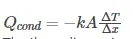
Fourier’s Law
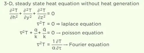
Fourier’s law states that the negative gradient of temperature and the time rate of heat transfer is proportional to the area at right angles of that gradient through which the heat flows. Fourier’s law is the other name of the law of heat conduction.
And
- Convection of Heat:In this process, heat is transferred in the liquid and gases from a region of higher temperature to a region of lower temperature. Convection heat transfer occurs partly due to the actual movement of molecules or due to the mass transfer.
Lows involves:
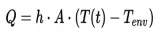
Newton's law of cooling:
The rate of heat loss of a body is directly proportional to the difference in the temperatures between the body and its environment.
CONTINUITY EQUATION IN THREE DIMENSIONS

- NS equation
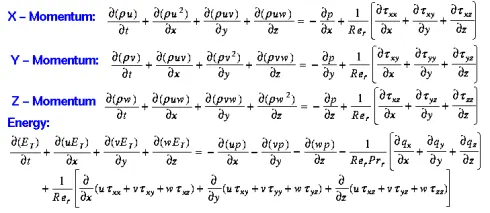
Above continuity equation is about the Mass conservation and momentum equation is about conservation of momentum.
Above 4 equation we found u,v,w,Rho and energy equation we found temperature(T).
heat transfer coefficient :
- Heat transfer coefficient depends on both the thermal properties of a medium, the hydrodynamic characteristics of its flow, and the hydrodynamic and thermal boundary conditions.
- Convective heat transfer coefficient on cold fluid side (Which in turn depends on flow velocity, turbulence, fluid viscosity, geometry of the surface etc.)
- Convective heat transfer coefficient on hot fluid side (Which in turn depends on flow velocity, turbulence, fluid viscosity, geometry of the surface etc.).
Post processing:
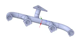
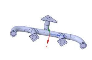
Here We Extract the volume to simulate a fluid (exhaust gas)was flowing inside the Exhaust manifold and name them as solid and fluid volume, In the solid volume conduction heat transfer was take place and through the fluid convective heat transfer take place.At the interference point CHT(Conjunctive heat transfer) take place ,That was the aria of analysis.

Here We we found Non-conformal Mash that shows the there is a physical gap in between the solid and fluid volume, but this create a problem to analyse the CHT in that surface so we re arrange the mash again.
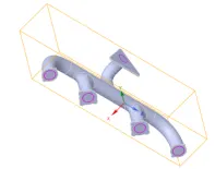
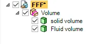

To Resolve This problem We should do the property shearing between the solid and fluid volume at the interference aria.To do so we have to Enable the shear topology and take the solid and fluid volume in one component. The pink circules are showing the shear topology.
These are the syntax:
to Enable the shear
Geometry>>FFF>> Enable the shear
Shear the property
Workbench>>shear prop
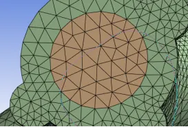
Now we get perfect-mash with proper arrangement mash without any Non-conformal Mash.
Setup
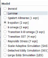
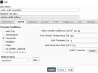
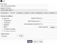
Now we set the solution in pressure based,steady,absolute and setup the physics in energy equation and K-epsilon turbulent model. Set the material in fluid is air and in solid is aluminium.
Then set the boundaries
- inlet velocity 5m/s
- Inlet tempreture 700K
- Outlet pressure 0 gauge pressure.
- In Outer wall convection set the thermal condition at convection and heat transfer co-efficient at 20W/m2K
- Other walls are adiabatic so we set the boundaries in heat flux at 0.
Solution
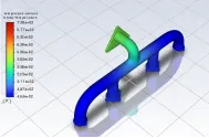
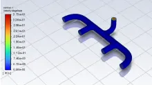
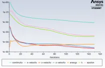
After done the all setup we create a tempreture couture and velocity couture to analyse the convective heat transfer and and the velocity of the exhaust gas. Here outer was heat rejection at the exhaust pipe is maximum but tempreture at inlet is maximum,this is due to the velocity of the exhaust gas , from velocity couture we found velocity of the outlet is maximum at the outlet because mass flow rate is maximum at the outlet .the above thick can be analyse properly by CFD POST and it can properly explain by the heat transfer co-efficient of the inner wall .
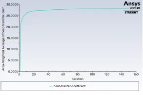

Now check Average heat transfer co-efficient of exhaust port is 28.102 W/M^2 K , Now found the highest value of the heat transfer co-efficient can check through CFD post
CFD POST
To transfer the date of the heat transfer co-efficient from Fluent to the CFD post we have to follow the following process.
Syntax:
Fluent>>file >>solution data ,then set file type in CDAT-Fluent post & Ensight, then select needed data.
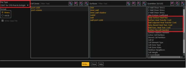
Then click on Write and save in the require location.
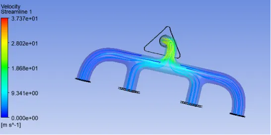
Here it shows that Heat rejection near the output is maximum and the the velocity was also maximum. The velocity of the output is maximum is due to the conservation of the mass. The outlet aria is nearly four time smaller then the inlet aria.
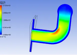
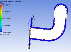
Now create a plane to analyze the heat transfer coefficient, then check the wall heat transfer coefficient is maximum at the inside curved region. The same we check in velocity plane we found velocity was maximum at that point.Due to higher velocity we found Reynolds no was high and due to higher Reynolds no Heat transfer co-efficient also higher.


Y+ region:
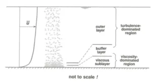
In turbulent boundary layer there is creating different sub-layer these are:
- Viscous sub-layer
- Buffer layer
- Overlapping layer
these are very small in the size, so to capture the data in that region,we have to create the small size mash. Here the viscous sub layer thickness was very small and upper layers are is in increasing in nature.
These layer are represent the y+ region and to capture the y+ region we create the influence layer.
Increases mash quality:


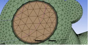
Now to increase the mash quality to analyze the values properly and now create the influence layer to analyze the heat transfer co-efficient in the interference aria .
Setup:
To create the inflation layer we name the inside wall as inflation layer so the there is a mismatch in the set up ,so match the two name in match zone pair. Then run the set up in previous boundary conditions.

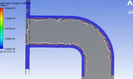
Now check the heat transfer co-efficient in the created surface found there is not any major change in heat transfer co-efficient .
Conclusion:
- CHT halp us to analyses the heat dissipation when fluid flowing inside the pipe and it help to find out heat transfer co-efficient fluid flowing inside it.
- The average heat transfer co-efficient of the exhaust gas is 28.102 W/M^2 .
- If we take consideration of the local heat transfer co-efficient, the heat transfer co-efficient is maximum ,where the velocity is maximum.
- So heat transfer coefficient is proportional to velocity.
- To capture the turbulent sub layer y+ region is needed ,because the sub layers near the wall is very small in size.
- Here after creating the inflation layer there is no change in the heat transfer co-efficient.