Week 4 - CHT Analysis on Exhaust port
ITRODUCTION:
Given the model to find the Convective heat tranfer coefficinet analysis on exhust port and also
crate the Contour plots and heat transfer plots
CONVECTIVE HEAT TRANSFER why and where used?
The transfer of heat one place to another by the movement of fluids. convectin usualy the dominent form of heat transfer in liquids and gases.Although often discussed as a distinct method of heat transfer ,convective heat transfer involves the combine processes of conduction(heat diffusion) and advection(heat transfer by bulk fluid flow)
Convection is one of the essential types of hea transfer which involves the movement of hot molecules of qair and liquid in massive portion. Convection occurs when there is both diffusion and advection. It cannot happen in solid matter.The process of convection can occur both naturally and externally.
Example of convection heat transfer Refrigerator,Popcorn maker,Melting of ice,Air conditioner,Hot coffee etc,
CONVECTIVE heat transfer process is of fundamental importance in a variety of pracical application,such as in porous insulation ,cooling of rotating electric winding ,geothermal reservoirs,irrigation systems and the exploration of petroleum and gas fields.
PRE PROCESS:
STEP 1:
GEOMETRY
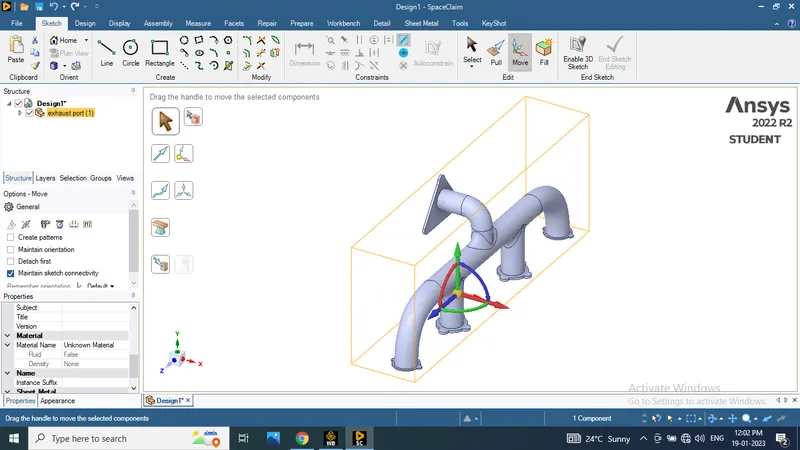
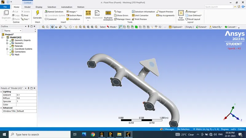
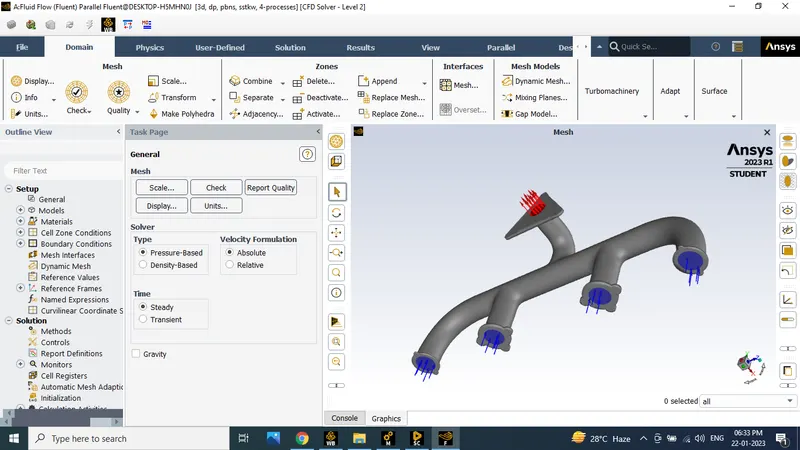
To open the ansys fluint workbench to creat the new fluent flow for fluid then open the geometric to opload the given model.
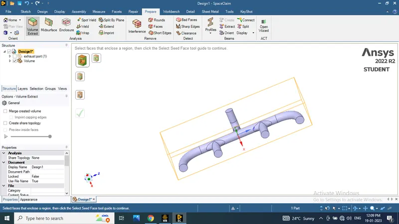
new sapce claim to open the given model using the volume create option to crete the volume in internal surface.
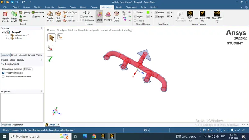
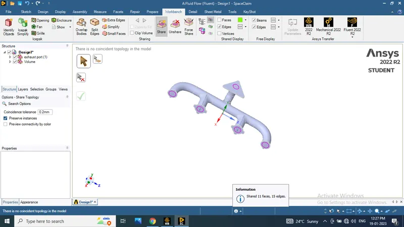
After using the shere topology to merge the all edges and faces
after finishing the share topology goin to the mesh
|
GIVEN MODEL
|
CREATE VOLUME
|
|
SHARE TOPOLOGY:
|
FINISHED GEOMETRY
|
STEP 2
MESH
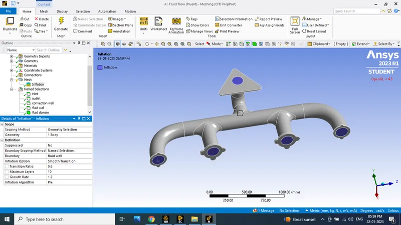
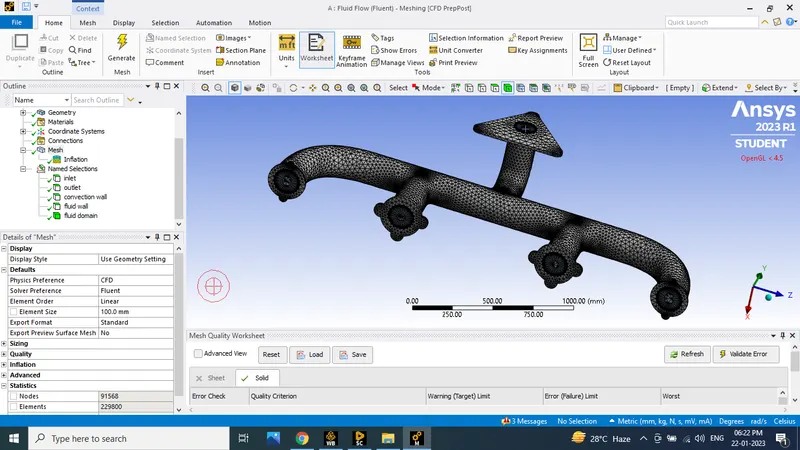
Mesh size is 100 mm and Inflation layer thicknes is 0.6 mm
To calculate the Y+ value in the given model to use the online calculator
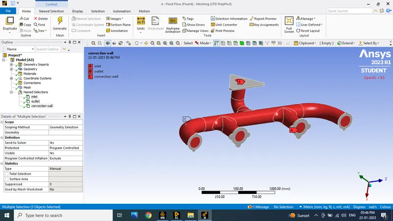
Name selection > mesh > inflation layer > update mesh
 |
NAME SELECTION
|
|
INFLATION
|
FULL MESH
|
STEP 3 :
SETUP
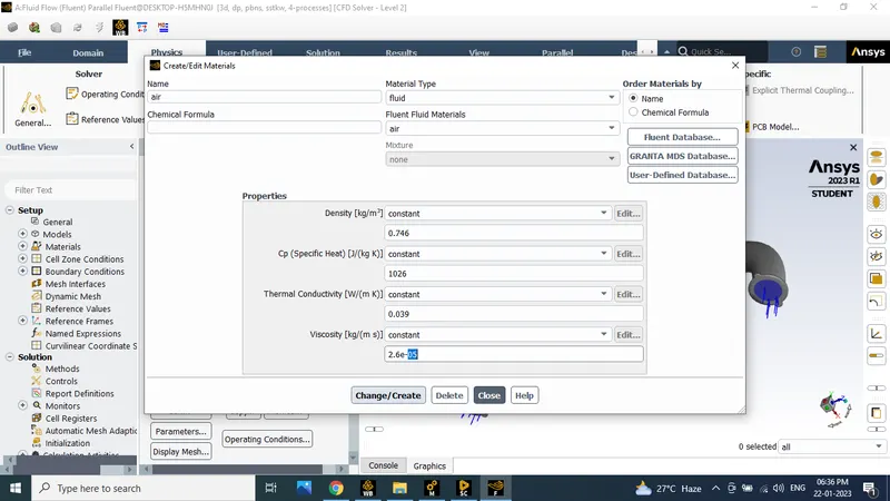
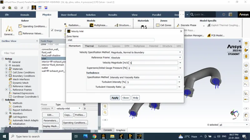
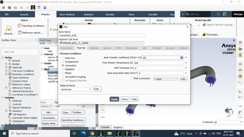
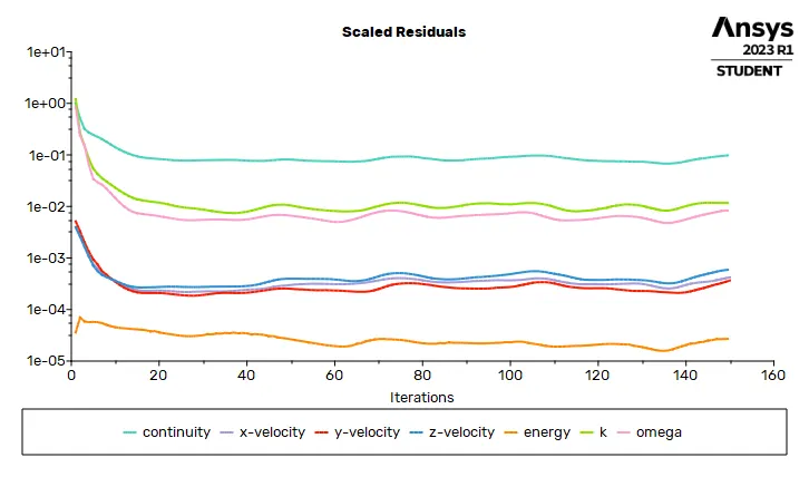
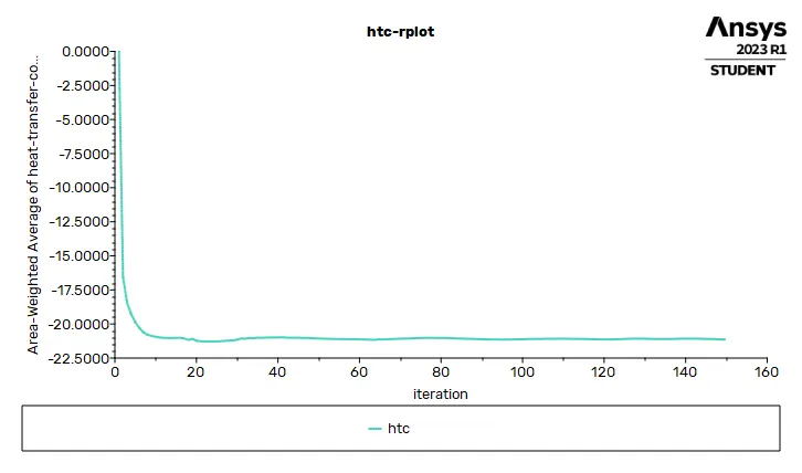
To set the materel properties and boundary layers and inlet outlet parameters values are set and iniialize after run the 150 iteration to create the htc report.
The material in air fluid that properties are
Density 0.746 kg/m^3
Cp(specific heat) 1026 J/kg K
Thermal conductivity 0.039 W/(m K)
Viscosity 2.6e^-5 kg/(m s)
And inlet velocity is 5 m/s and temperature 700 k
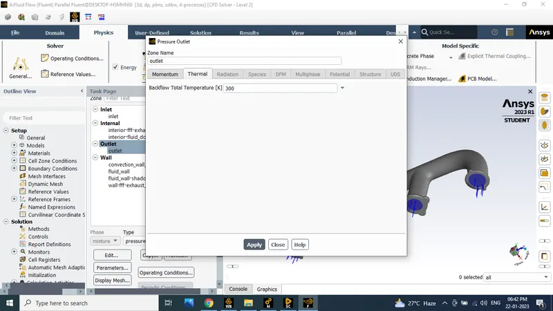
outlet temperature 300 k
heat transfer co efficient is 20 W/(m2 K)
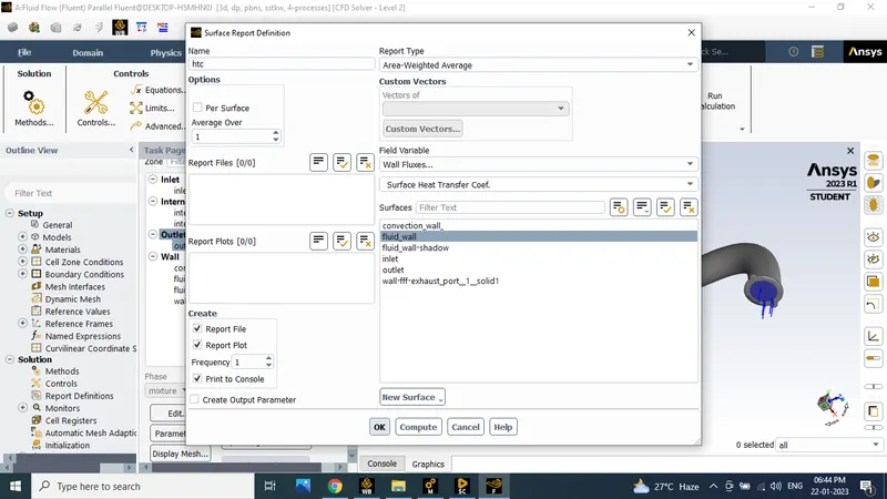
then create the new surfce avg report for heat transfer coefficirnt report
 |
MATERIAL PROPERTIES
|
|
INLET VELOCITY 5 m/s TEMPERATURE 700 K
|
HEAT TRANSFER COEFFICIENT OF COVECTIONAL WALL
|
|
OUTLET TEMPERATURE 300 K
|
SURFACE REPORT
|
|
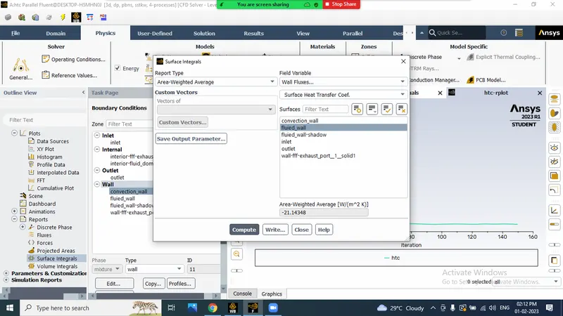
HEAT TRANSFER COEFFICIENT FOR SIMULATION
|
RESIDUAL PLOT
|
|
HTC PLOT FOR 150 ITERATION
|
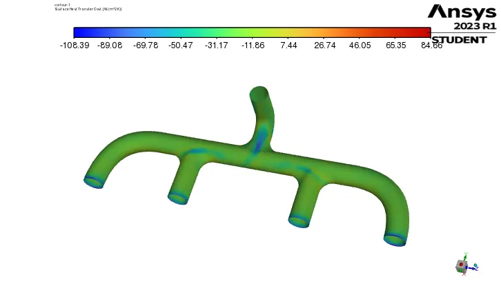
CONTOUR FOR HTC
|
STEP 4
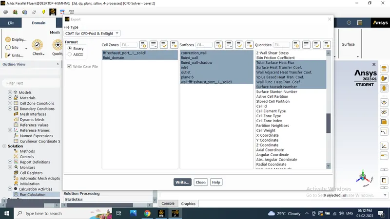
The inlet and outlet full report are make a cdot file in comparison purpose
POST PROCESS
STEP 5
RESULT
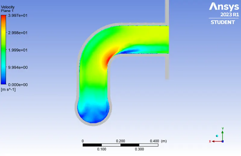
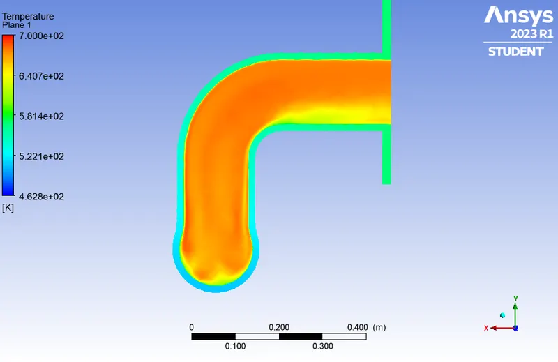
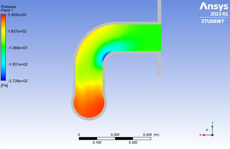
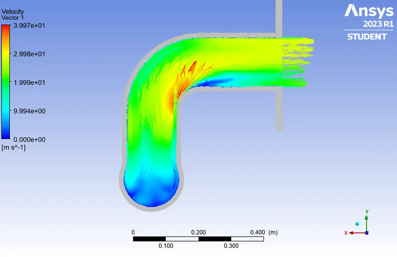
To crete the outlet xy plane cut section and to find the pressure and velocity contours
and alredy save the cdot report are uploat the result time the infaltin HTC contour is viewed
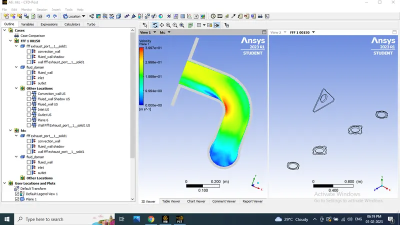 |
VELOCITY CONTOUR FOR OUTLET
|
|
TEMPERATURE CONTOUR
|
PRESSURE CONTOUR
|
|
VECTOR CONTOUR
|
SURFACE HEAT TRANSFER COEFFICIENT
|
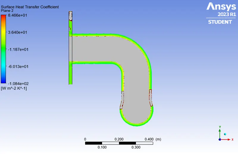
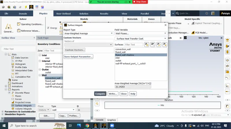
In Simulation time we get the heat transfer coefficient is 21.143 W/m^2 K
COMPARE THE SIMULATION AND ANALYTICAL HTC VALUES :
simulation value
ANALYTICAL METHOD:
Avarage temperature in 200 c
`Re= (rho*v*l)/mu`
`Nu=(h.l/k)`
`Nu=0.023*Re^0.8*Pr^0.33`
rho= 0.746 kg/m^3
mu=25.99*10^-6 Ns/m^3
v=34.85*10^-6 m^2/s
k=0.03931 W/mK
Pr=0.680
l=0.16 m
calculate the Re
`Re=(0.746*34.85*10^-6*0.16)/(25.99*10^-6)`
Re=0.1600
calculate Nu number
`Nu=0.023*0.1600^0.8*0.680^0.33`
Nu=0.0046
`h=0.0046*0.03931/0.16`
h=0.0011
Simulation and analytical value so many difference occured
RESULT:
We give the heat transfer coefficient is 20 W/m2 K after the simulation we get the h value is near but analytical method we found the huge difference fronthe htc.
and all simulation , plots and countours are showed.