Week-4 Challenge WOT Condition Part-2
AIM :-
- To differentiate between mapped and dynamic model of engine, motor and generator in the powertrain blockset. How can the model type be changed?
- To determine how the model calculates miles per gallon and what are the factors that the model takes into consideration for calculations.
- To run the HEV RefernceApplication simulation using the Wide Open Throttle (WOT) drive cycle and changing the gradient and wind speed in the environment block.
- To run the EV ReferenceApplication using the same parameters from HEV ReferenceApplication and compare the results.
THEORY :-
Powertrain Blockset is an add-on developed by MATLAB which provides fully assembled reference application models of automotive powertrains, including gasoline, diesel, hybrid, and electric systems. It includes a component library for simulating engine subsystems, transmission assemblies, traction motors, battery packs, and controller models. Powertrain Blockset also includes a dynamometer model for virtual testing. Powertrain Blockset provides a standard model architecture that can be re-used throughout the development process. It can be used it for design tradeoff analysis and component sizing, control parameter optimization, and hardware-in-the-loop testing. Models can also be customised by parameterizing components in a reference application with one's own data or by replacing a subsystem with one's own model.
The list of applications in powertrain blockset are,
- Reference Applications: Which provide reference simulation models of IC Engines both CI and SI, Hybrid vehicles and pure electric vehicles. The reference application includes plant models, controllers, a longitudinal driver, and drive cycle data.
- Mapped and Dynamic Models: Mapped engines represent macro engine behavior as a set of lookup tables (brake torque, fuel flow, air mass flow, exhaust temperature, efficiency, and emissions) as functions of commanded load and measured engine speed. Dynamic engines decompose engine behavior into individual component models that account for engine dynamics, most notably intake airflow and turbocharger dynamics.
1. DIFFERENCE BETWEEN MAPPED AND DYNAMIC MODEL :-
If the type of SI or CI engine needs to be customised in the reference application models, a user can choose between mapped and dynamic models. These models also exsist for electric motors and generators for HEV and EVs.
Mapped Model: This model uses a set of steady state lookup tables to characterize the engine/motor/generator performance. These tables provide engine/motor/generator characteristics . This model is used if the data is already available or if quasi steady-state engine simulations need to be run.
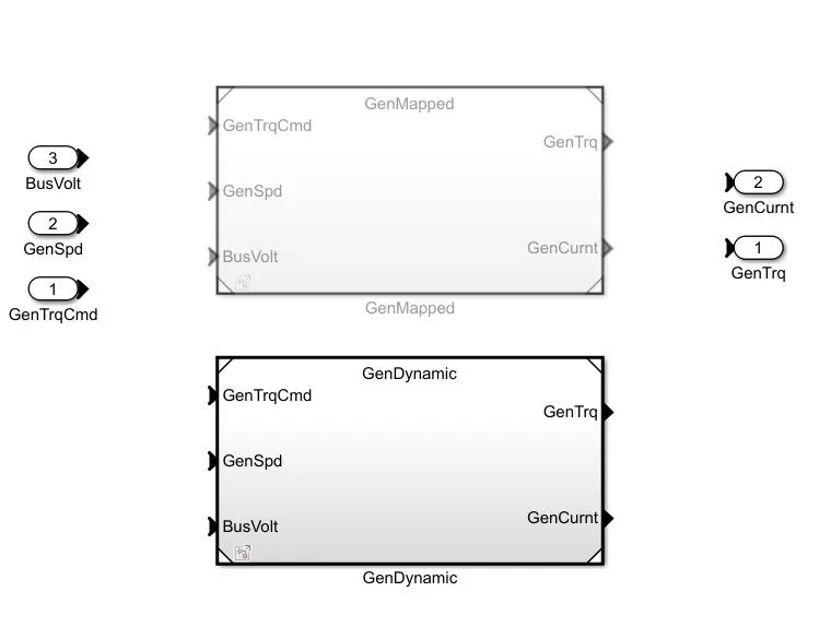
Dynamic Model: This model breaks down the engine/motor/generator characteristics that are separated in lower level components. By combining components in this way, the models capture the dynamic effects. This model is used if the user requires more detailed dynamic and component level data simulations. It is also used to analyze the impact of individual engine/motor/generator components on the overall performance.
How can the user change between Mapped and Dynamic models?
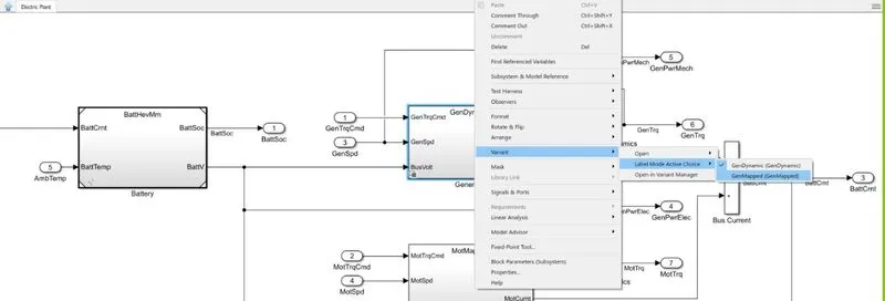
- First the Refernce application model should be opened.
- Then select the passenger car block. Inside this block select the electric plant subsystem.
- Once the electric plant subsystem is opened, the above subsystem appears. The picture above is the generator of a hybrid vehicle.
- Select the Generator block and it will open having the two mapped and dynamic subsystems. By default the Mapped subsystem is used and the Dynamic model is commented out.
- To change the models, go back to the previous subsystem and right click on the generator block.
- Then select the option variant. Under this option choose Label mode active choice and select either mapped or dynamic as shown in the figure above.
- Depending on what the user chooses the other model will get commented out.
2. HOW DOES THE MODEL CALCULATE MILES PER GALLON. WHAT ARE THE FACTORS AFFECTING FUEL FLOW :-

Miles per gallon is calculated in the visualisation block. The subsystem shown above performs the calculations. The subsystem uses a combination of constant, gain and operator blocks to determine the MPG. But in case of hybrid electric vehicles, Miles Per Gallon equivalent (MPGe) is used which indicates the economy of the vehicle when driven in electric mode. It is similar to MPG, but instead of presenting miles per gallon of the vehicle’s fuel type, it represents the number of miles the vehicle can go using a quantity of fuel with the same energy content as a gallon of gasoline.
Characteristics that are taken into consideration for calculation of MPG from the block diagram are,
- 33.7 KW-hrs of electricity is equivalent to 1 gallon of fuel.
- The power of the battery and the speed of the vehicle combined help in calculation MPGe.
- The volume of fuel flow is also considered.
3. HEV RefernceApplication MODEL SIMULATION :-
The HEV ReferenceApplication model is run by changing the following input parameters,
- The Wide Open Throttle (WOT) drive cycle is selected.
- The gradient and wind speed are changed.
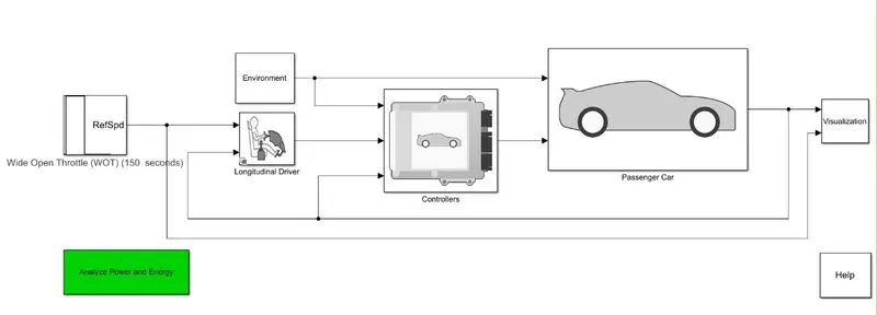
First the HEV RefernceApplication model is opened in simulink. Under the input parameters the drive cycle is selected. Here the WOT cycle is chosen where the nominal reference speed, time to start deceleration and simulation time are determined.
Once the drive cycle input is determined, the environment block is selected. Under the environment block the gradient and wind velocity are changed as shown below to 12% and 5 m/s.
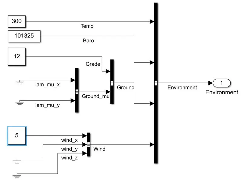
Once these 3 input parameters are defined the simulation is run for the same amout of time defined in drive cycle block.
The plots of the simulation are shown below.
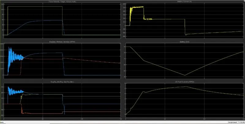
The list of plots obtained are,
- Vehicle velocity.
- Engine, motor and generator speed.
- Engine, motor and generator torque.
- Battery State of Charge (SOC)
- Battery current.
- MPGe.
From the graphs we can see that the speed increases from 0s till 75s and from there the vehicle starts to decelerate till it reaches 0m/s.
The battery state of charge shows that the battery percentage is at 80% before the vehicle starts moving and rapidly decreases by 30% during the wide open acceleration stage. During the deceleration stage, due to the regenerative effect of the generator the battery SoC increases by 20% from 55 to 75%.
It is also observed that the MPG increases slowly with some fluctuations over the duration.
4. EV ReferenceApplication MODEL SIMULATION :-
The EV ReferenceApplication model is run with the same input conditions of the HEV model where the drive cycle, gradient and wind velocity are changed.
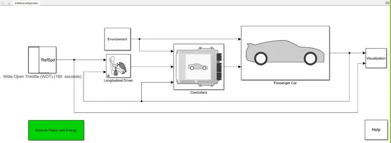
The same speed conditions and simulation time are considered for the simulation and then it is run. The plots of the results are shown below.
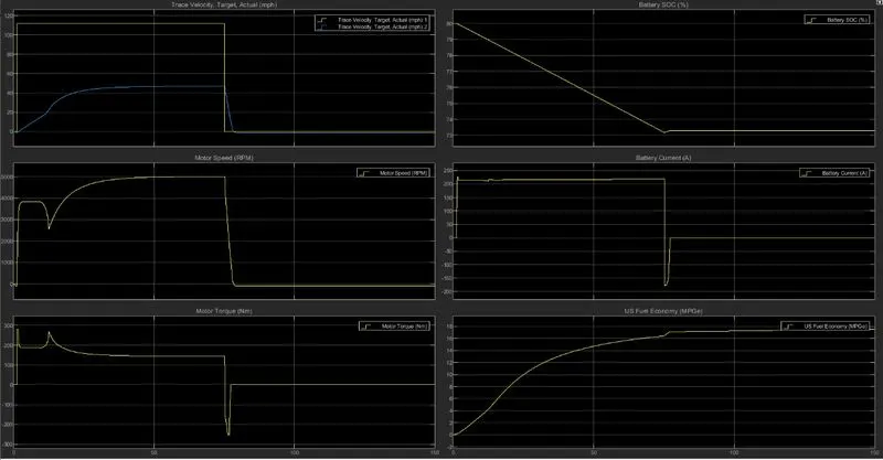
The list of plots obtained are,
- Vehicle velocity.
- Engine speed.
- Engine torque.
- Battery State of Charge (SOC)
- Battery current.
- MPGe.
The vehicle speed can be seen to increase to it's max speed from 0s and maintains it's speed while it decelerates rapidly to 0m/s and remains zero.
The battery SoC starts to decrease as the speed increases from 80 to 75% but receives a mild regenerative effect during deceleration due to the regeneration but it is a nominal increase of about 3%.
CONCLUSION :-
- The differences between Mapped and Dynamic models in powertrain blocksets were differentiated and the procedure to change between the models in the powertrain blockset is determined.
- The Miles Per Gallon (MPG) subsystem and the characteristics that are considered for calculation are explained.
- The HEV ReferenceApplication model is simulated by changing the required parameters and the results were obtained.
- The EV ReferenceApplication model is simulated using the same parameters from the HEV model and the results were obtained.