Week 4 Challenge : CFD Meshing for BMW car
Aim: To perform the CFD mesh on the geometry for the given target length and quality criteria after clearing all the errors in the geometry.
Objective:
- Select the Symmetric half section of the geometry with the lowest errors.
- Solve all the error present in the geometry without affecting the outer body design.
- Name the PID's.
- Mesh the geometry for the given CFD target length and quality criteria.
- Symmetry(mirror) the other half to complete the geometry.
- Creating the wind tunnel.
- Meshing the wind tunnel(Surface and Volumetric Mesh).
Content of the body:
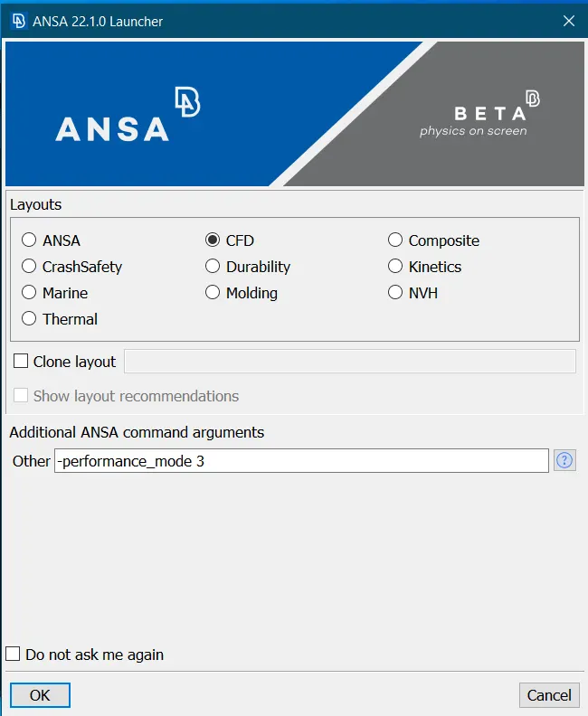
- Open the ANSA with the performance mode 3.
- .
- .
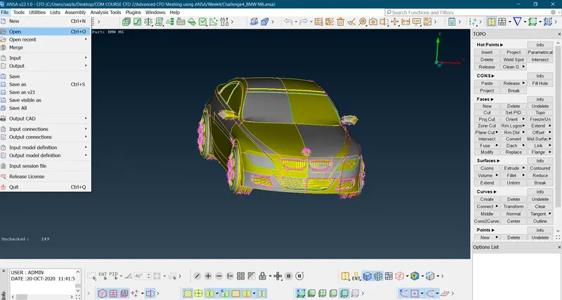
- Then import the geometry using the open command from the file menu:
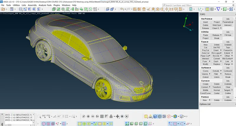
- As the geomety model is symetric we can make use of the one half for reducing the cleaning time and resources used, then after it can be mirrored and the mesh and simulation can be performed.
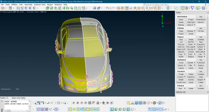
- Selecting the half for the deletion:
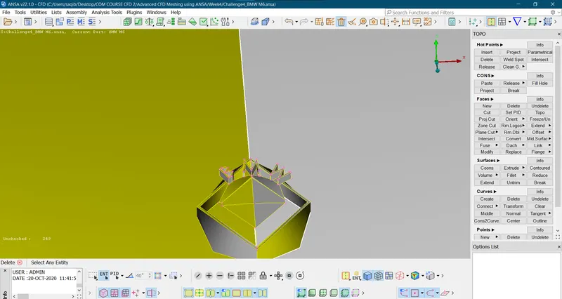
- Deselecting the logo:
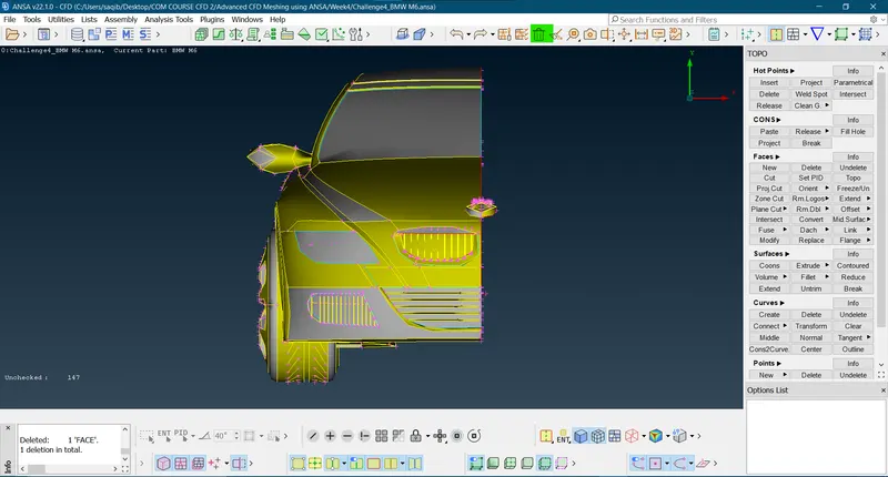
- After deleting the half:
- Now for better prceding we have to increase the resolution as it is very course.
- It can be done by many methods but here we are using the perimeter length to define the length to very fine resolution(1mm).
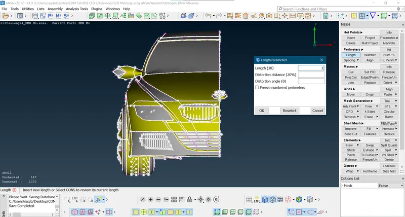
- After defining the length of perimeter:
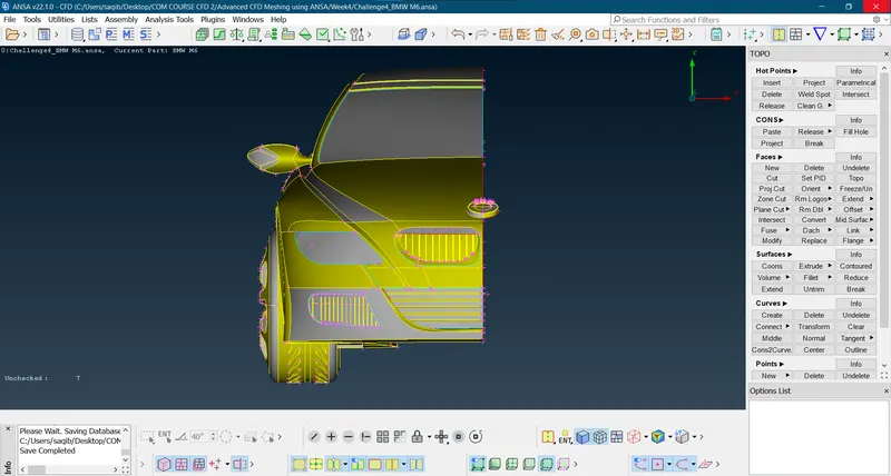
- As we can see the resolution is incresed and is optimum for proceding to next step.
- We are going to proceed in sequential manner:
- Cleaning:
- Head light: We require only the external part of the head light, so we will delete the all un wanted inner parts so to reduce the mesh count and processing time.
- By using the iNOT option dect the head light and click the middle mouse so show only the head light:
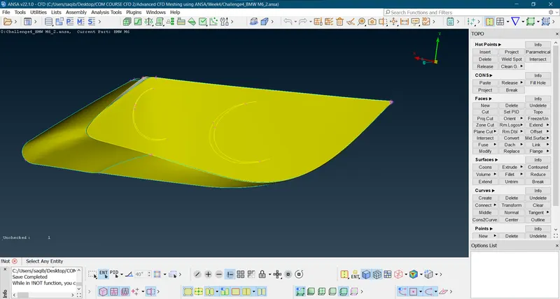
- Now start deleting the all the inner unwanted parts of the head light using delete command:
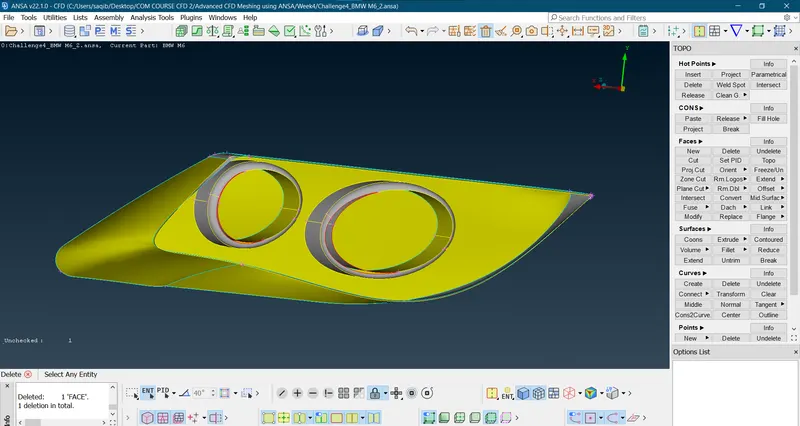
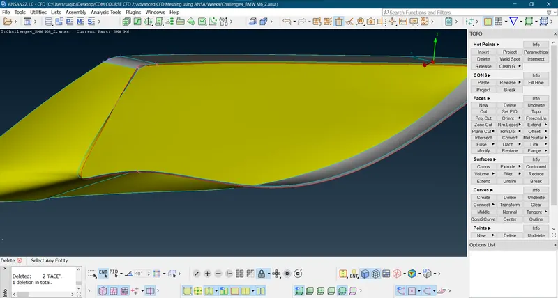
- Now checking which surfaces of the head light are needed by showing all components and deleting the remaing surfaces:
- After deleting all the unwanted surfaces:
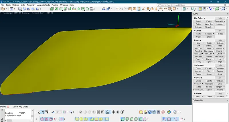
- Now there is an single cons present in the area of head light, so to fix it use the paste cons options:
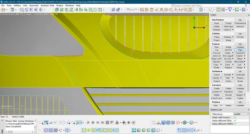
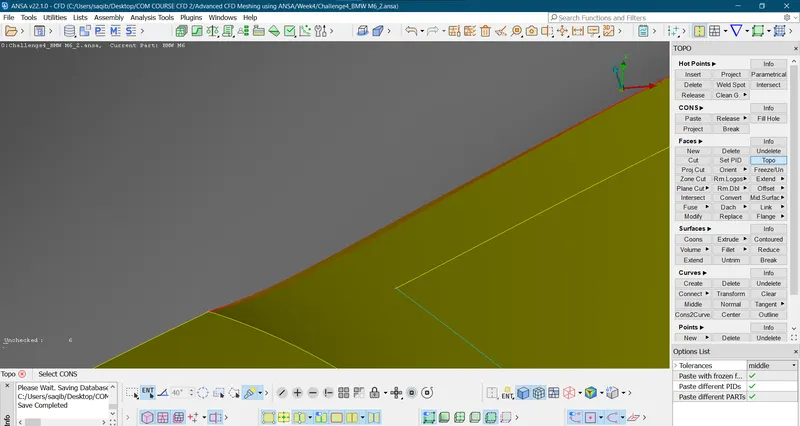
- The paste option creates a small surface which may incure an error so to avoid it we use cut option to create new cons and delete the fault surface and create new surface which has no error/single cons.
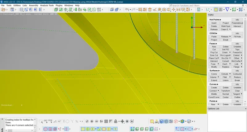
- Now the surface is fixed.
- Optical Rear view mirror:
- First checking the overlapping/double surfaces:
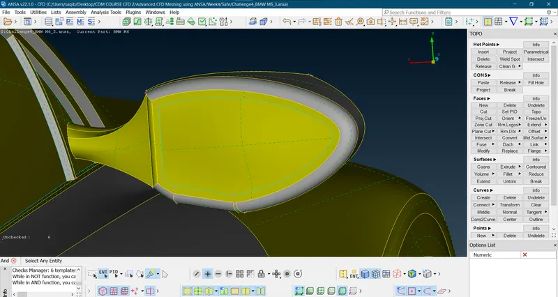
- There are internal surfaces which are not participating in the external airflow:

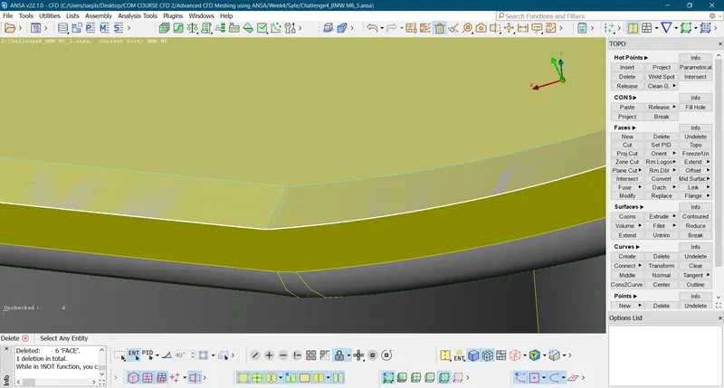
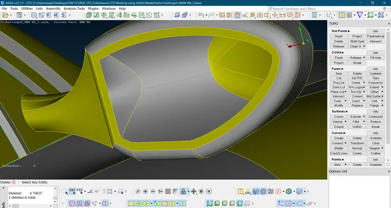
- Now the internal surfaces are deleted.
- Now as it can be seen there are faces which are not intersecting:
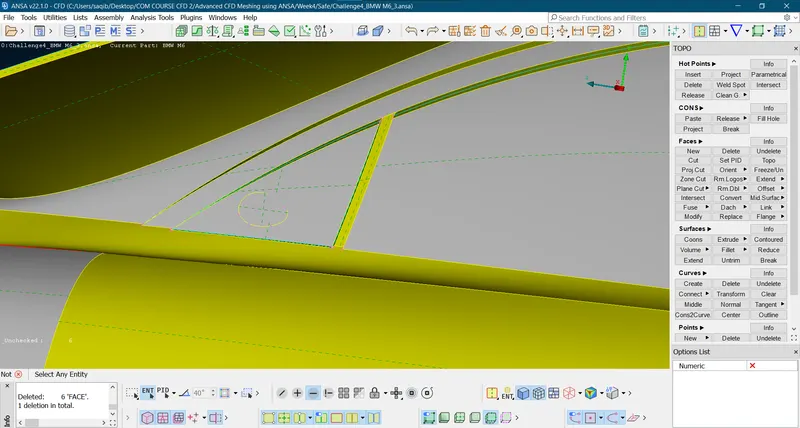
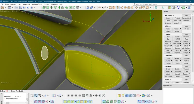
- Deleting this face:
- Now project the cons to the surface:
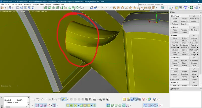
- Doing the topo to join the cons:
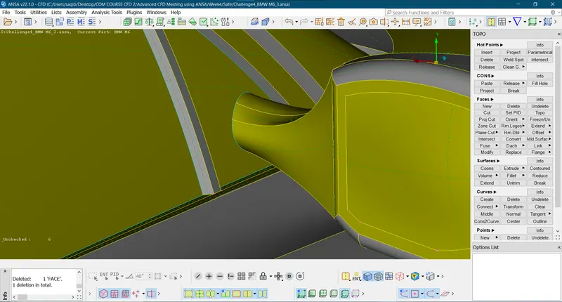
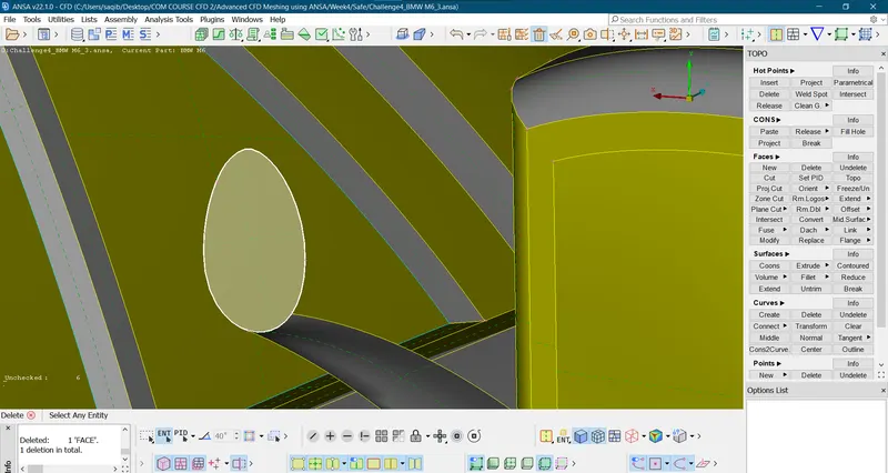
- Now we have double cons:
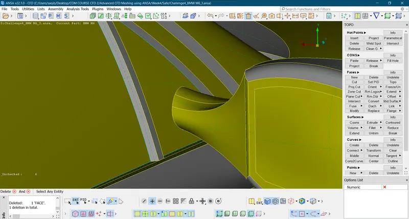
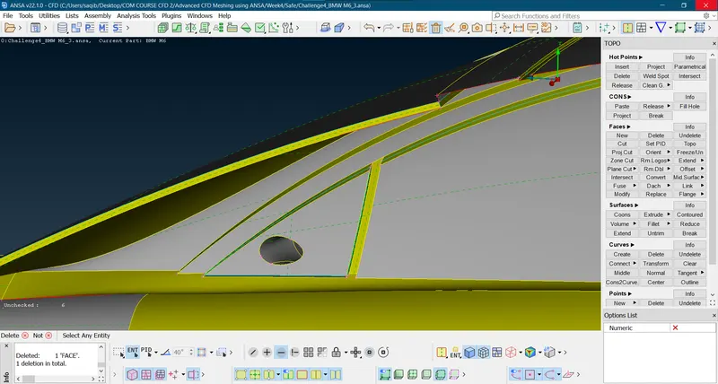
- Now the mirror is in contact with the window surface with no repeating/triple cons.
- Lower Grills:
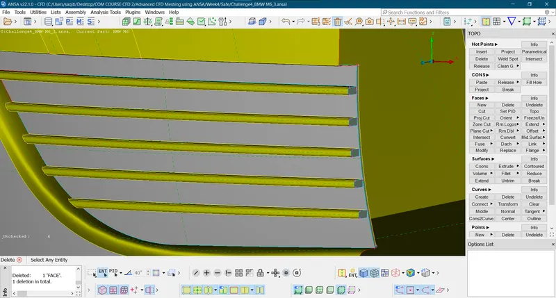
- There are many closed surfaces that do not have any useful outcome in the external airodynamic analysis, so deleting the closed surfaces.
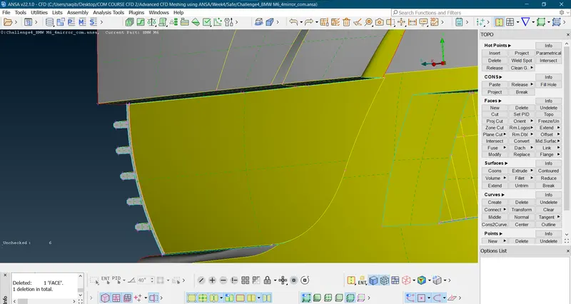
- The back plate is also not needed.
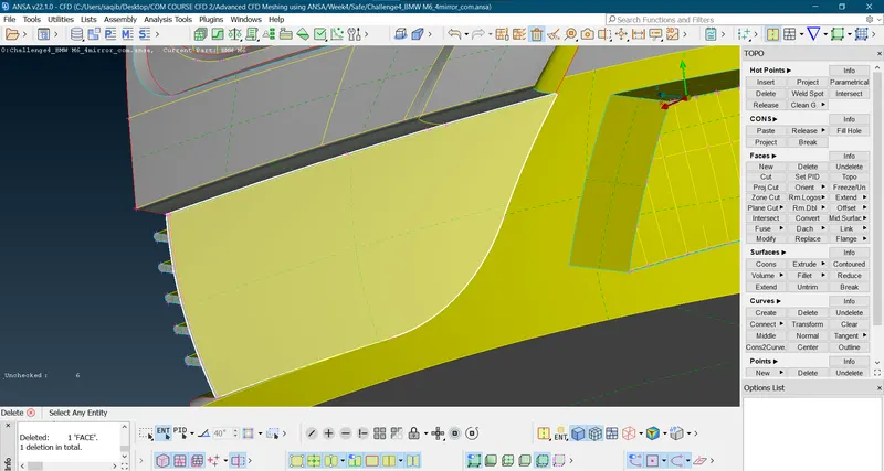
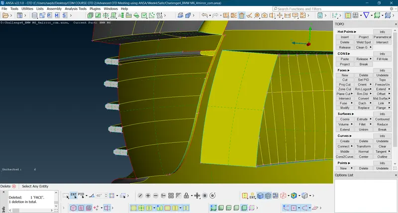
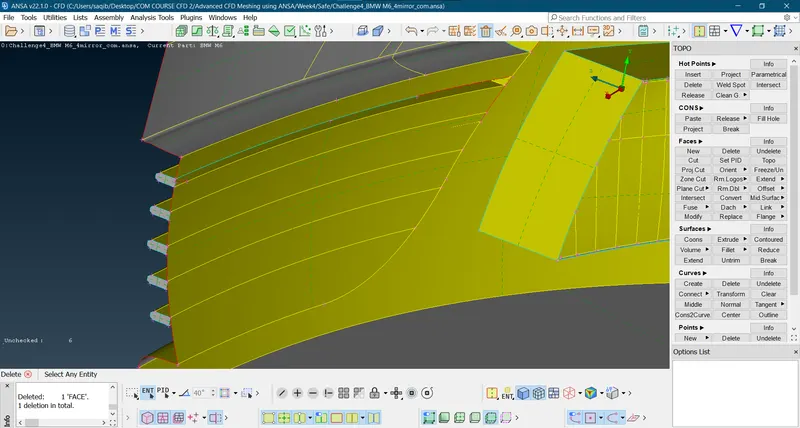
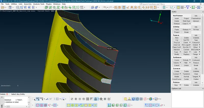
- Clearing the triple cons:
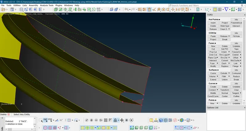
- Now deleting the surface penetrating in the grill:
- Intersecting and deleting the penetrated surface:
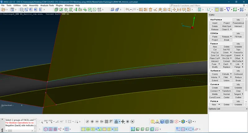
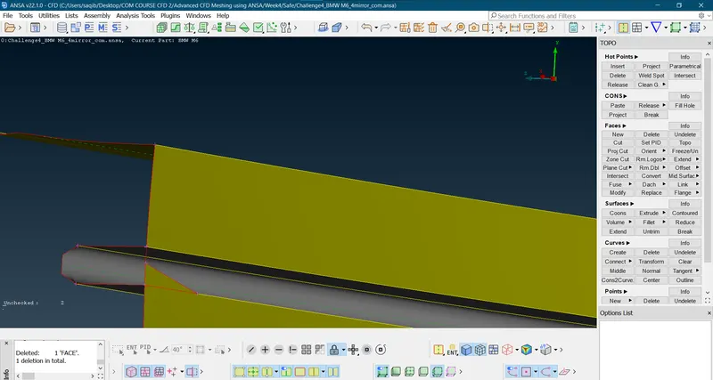
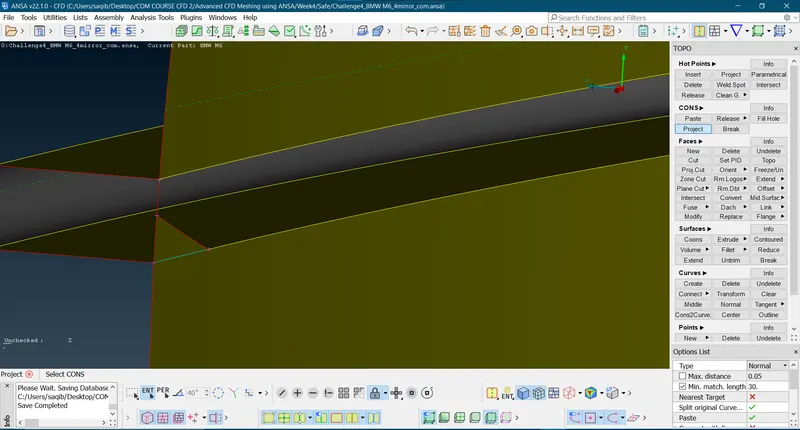
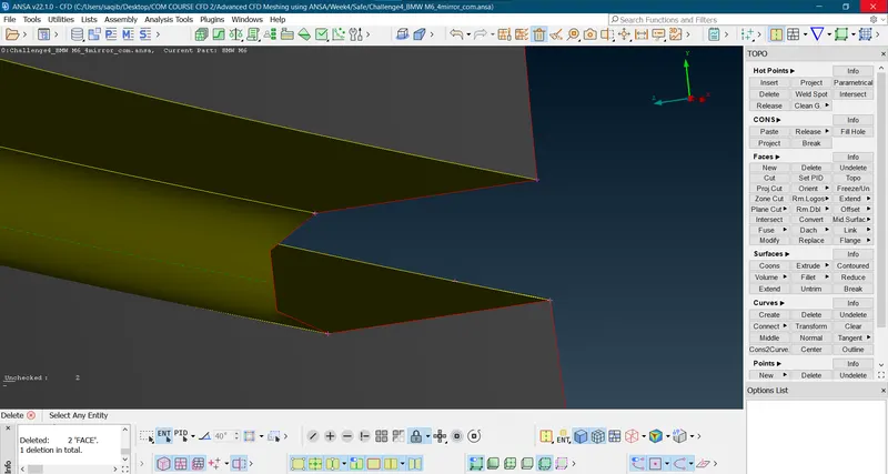
- Using the cut option and deleting the surface gives te following geometry.
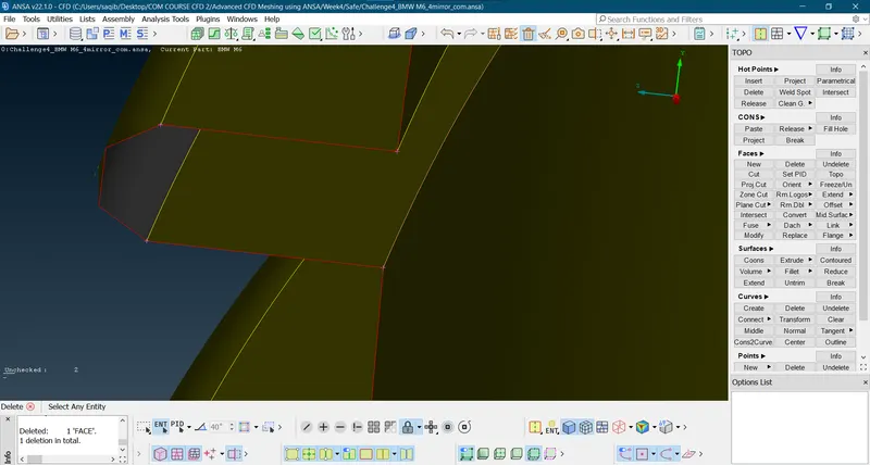
- Now deleting hotpoint by releasing the cons and doing topo again we get the above geometry.
- Clearing the other side of the grill:
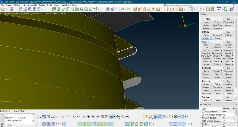
- Intersecting the single cons.
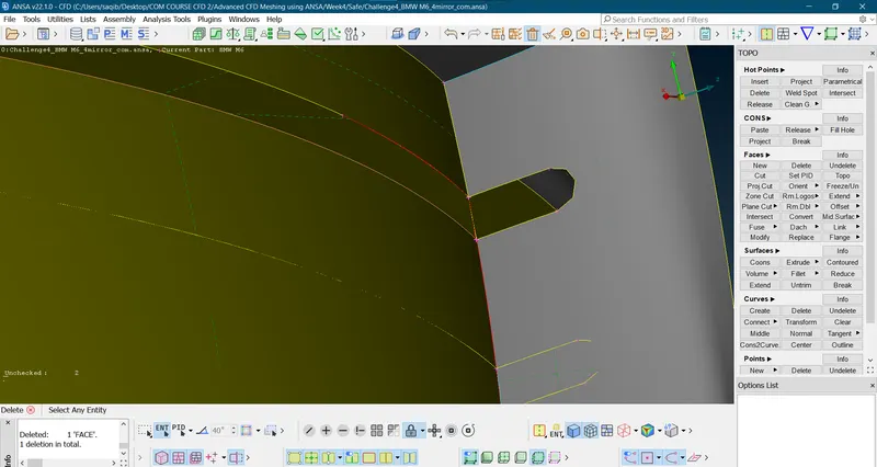
- Deleting the single, triple cons and hot points:
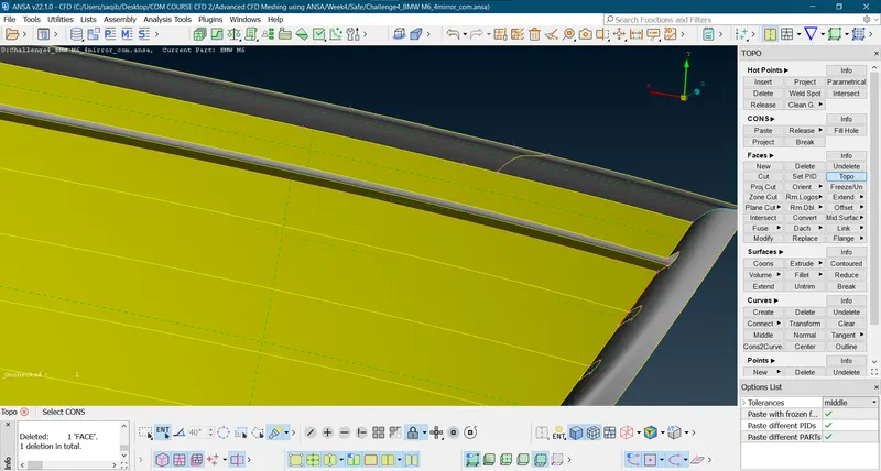
- Now deleting the inner surfaces of the bars of the grills:
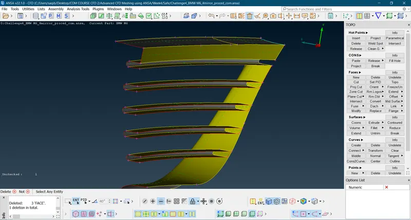
- By projecting and deleting the cons an the surfaces:
- An surface error is encountered:
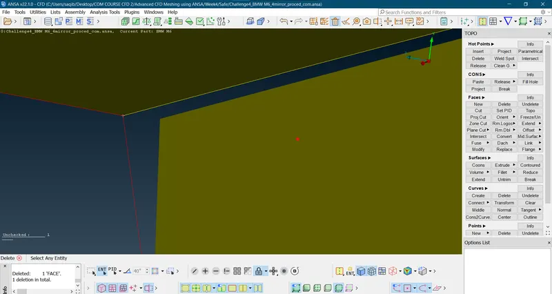
- This can be fixed by deleting the old surface adding a new surface:
- There is the incomplete cons on the either side of the surface so using the cut option to complete the cons.
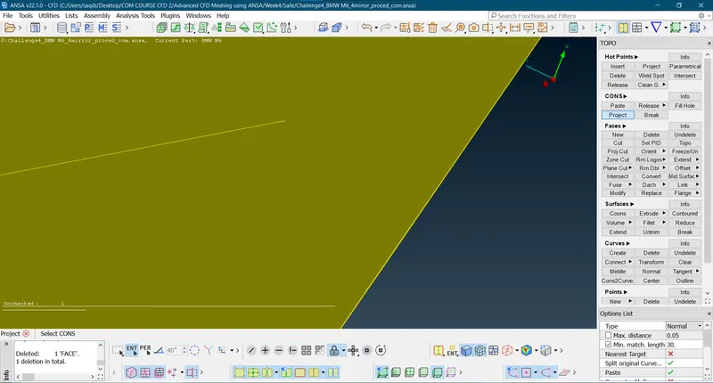
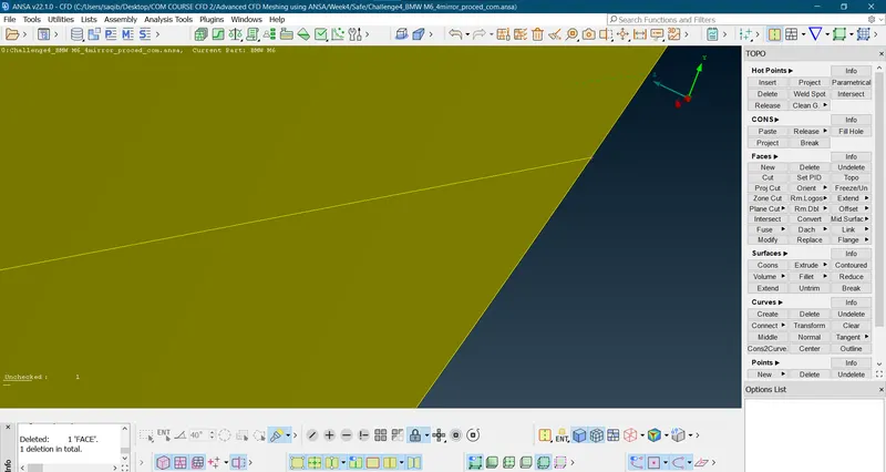
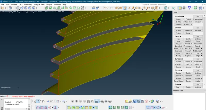
- Following for all the bars in the grill:
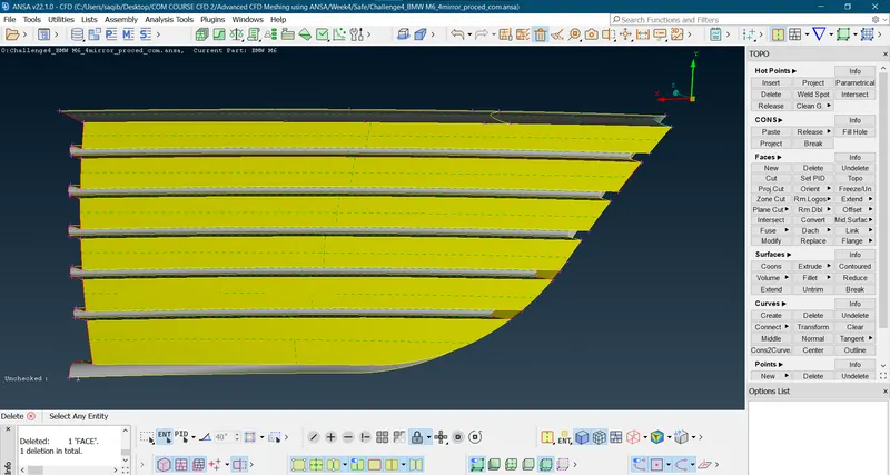
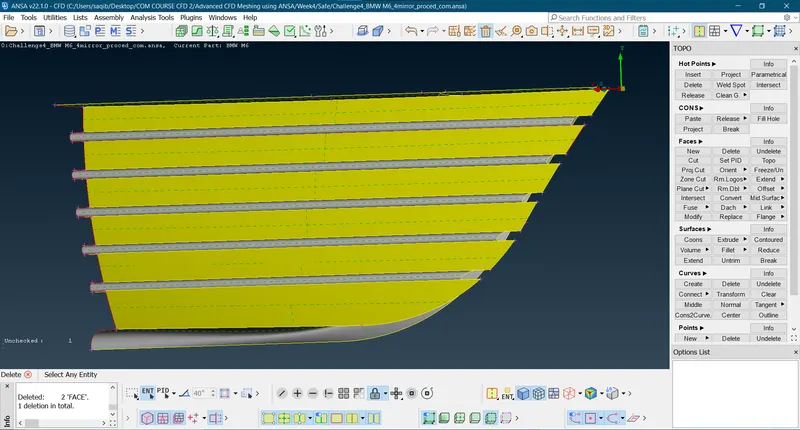
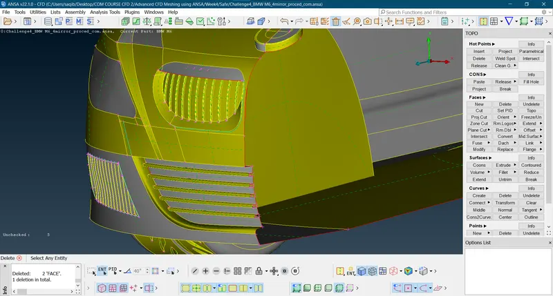
- Small grills:
- Surface of the bars are not intersecting with the back plate:
- Isolating the lower small grill for easy operations:
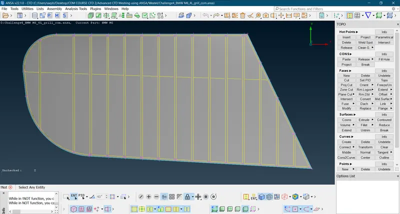
- Using the iNOT option.
- As there is no intersection of the fins of the grills to the back plate:
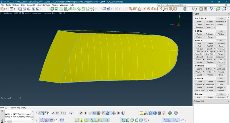
- Deleting the back plate as we will be modelling new more optimized surface:
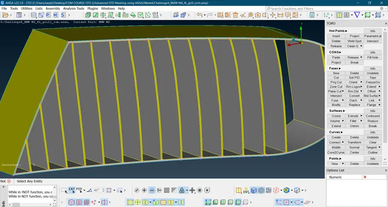
- As the outer edge contains triple cons it means it is directly connected to the outersurface of the car we can delete the surface not in use:
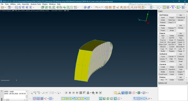
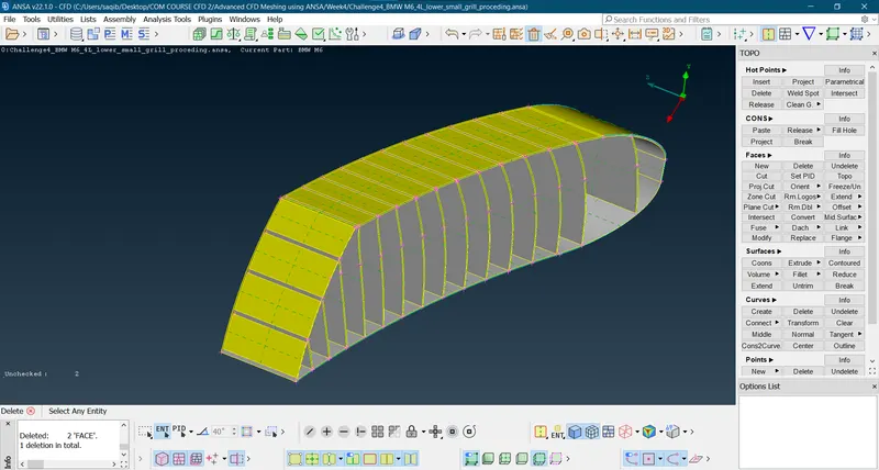
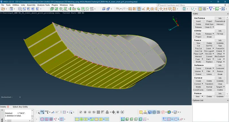
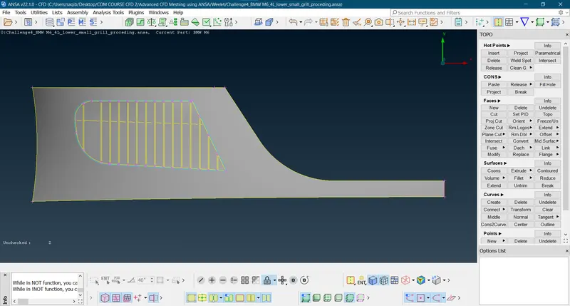
- Seleting the around entities to check the needed surfaces and deleting the not requried ones:
- The triple cons creating surfaces are not requried so delete them(keep the surface which coonects the bumper and the grill):
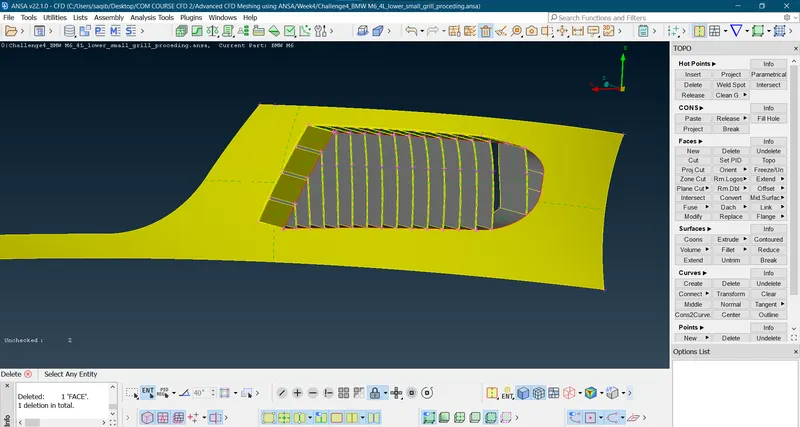
- Deleting the back surface of the fins as the fins are covered from outside:
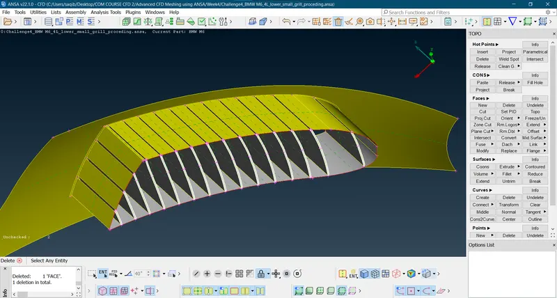
- Uncut the inner fin surfaces:
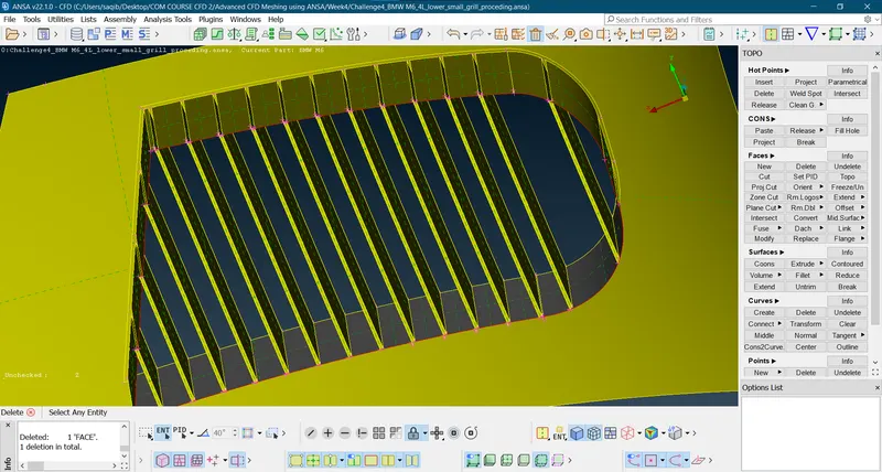
- Deleting the inner fins surfaces:
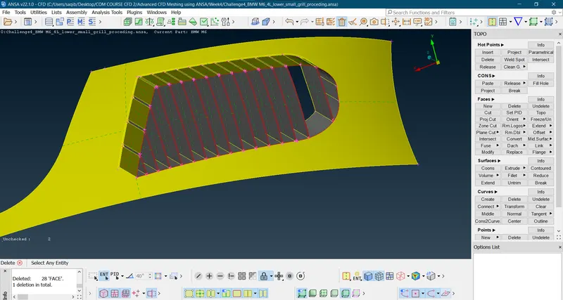
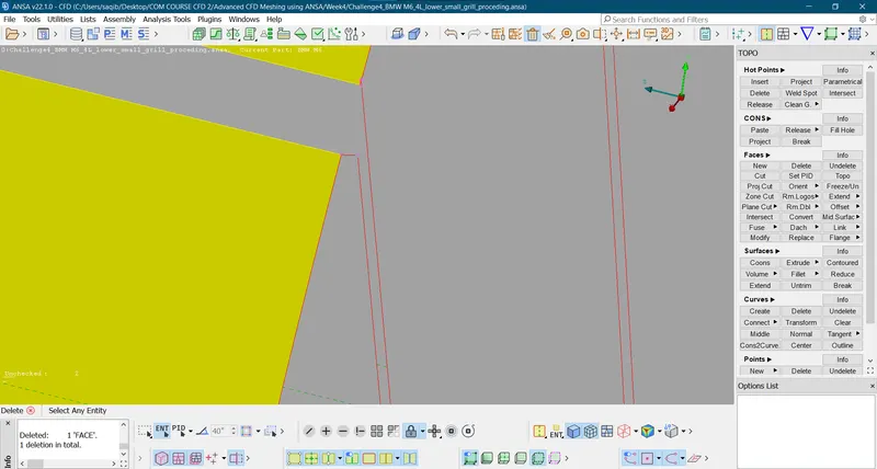
- Deleting the extra coons by using the cut and delete.
- Making new syrface to cover the inner surface and eleminating the extra area:
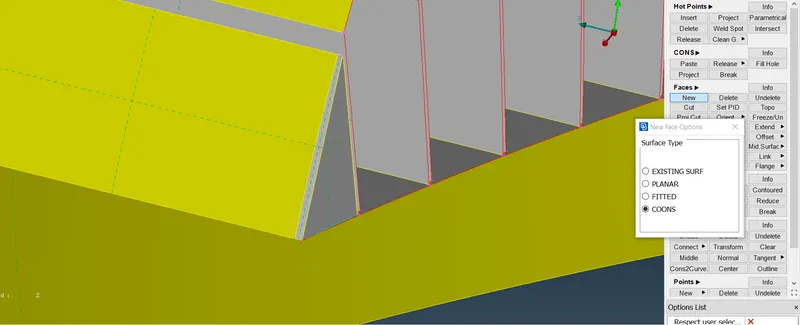
- To the full surface as one delete the surfaces and the unnecessary hotpoint and create a singl new surface:
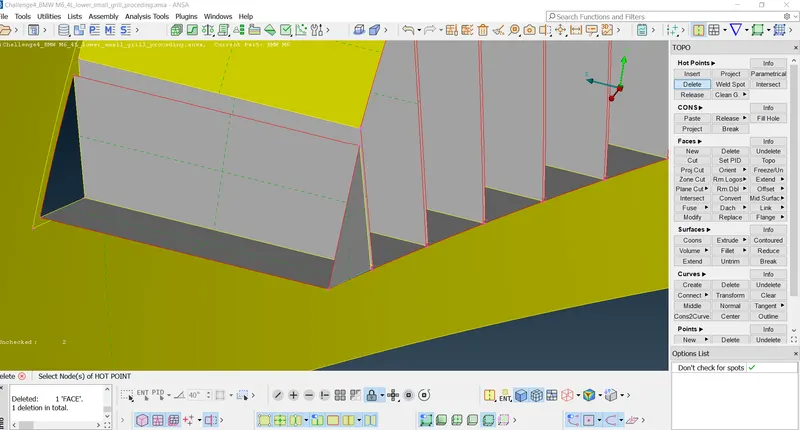
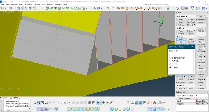
- creating the new surface:
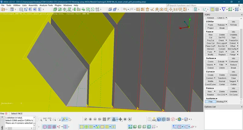
- Following this procedure for all other fins:
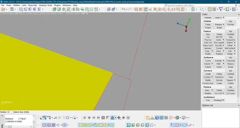
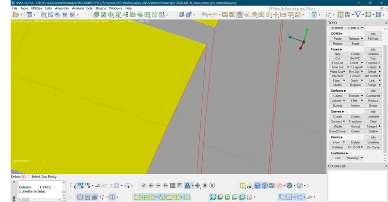
- For some surfaces deleting and creating the new surface is better option:
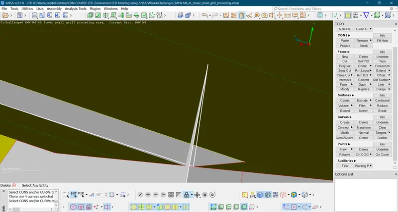
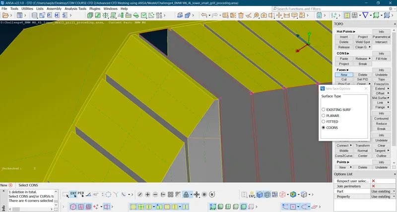
- Deleting the surfaces and creating the new surfaces to avoid errors:
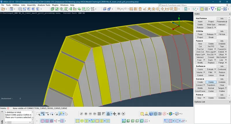
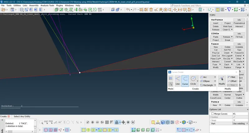
- Here we are able to see there are surfaces which are improperly allinged.
- So fix them:
- Create the curves to the proper point of meet.
- Using the curves2cons command capture the outer profile of the fins.
- Now delete the repective fins surface and create the new surface using the corrected cons.
- As the upper surface has errors which are causing the errors for the new back closing surface to form so deleting the upper surface.
- And create the top cover then the back cover of the fine using new surface command with coons options.
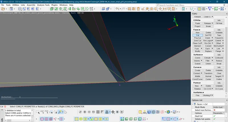
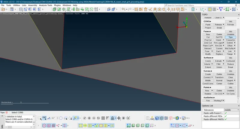
- Now for the last fins there are some errors:
- First create the coons for the inner surfaces of the using the cut option by selecting the relevent area of the surface which is in use for the aerodynamic analysis.
- Create the new surface directly in the upper portion is causing the errors so keep the hotpoint and create the surface.
- Cover the back fin surface using the new coons created for the surface in accord to the analysis.
- Now delete the extra edges causing the tripple coons created by eleminating the surfaces not useful in the analysis.
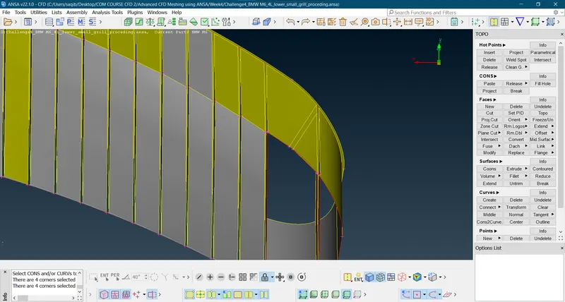
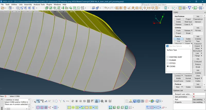
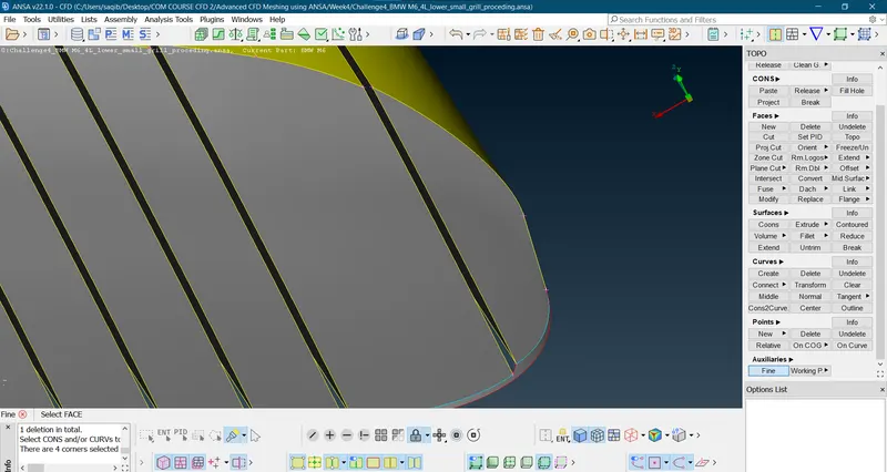
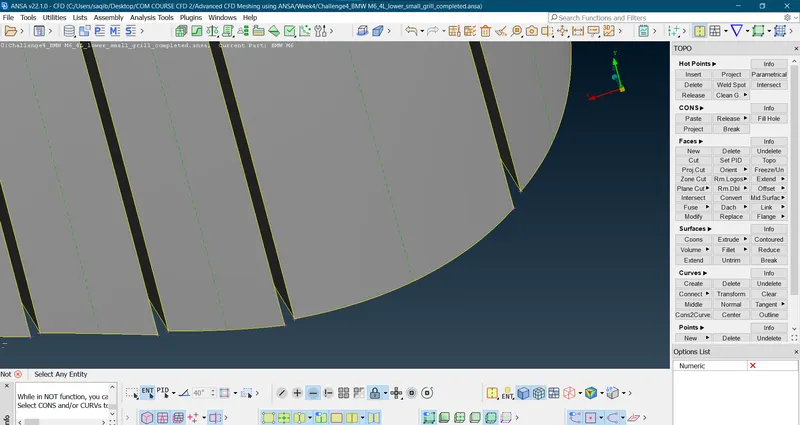
- There are some errors in the right side of the cover surfaces:
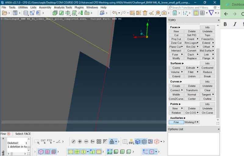
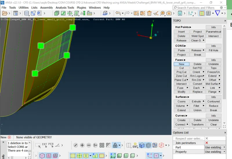
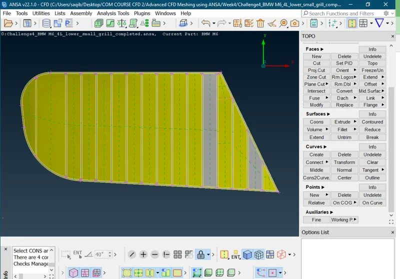
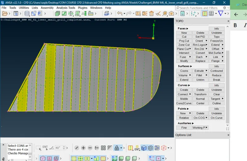
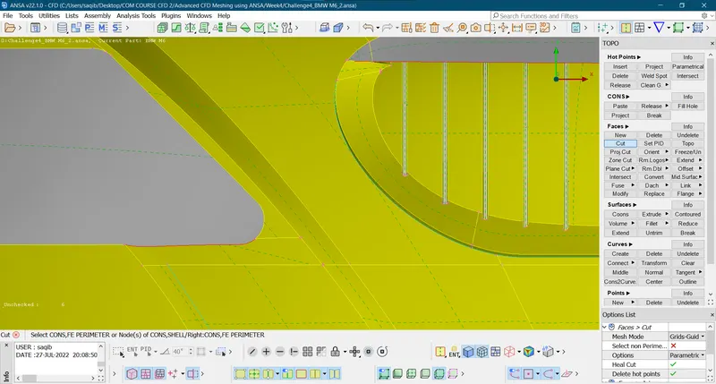
- Surface of the bars are not intersecting with the back plate:
- Upper Grills:
- Create the new surfaces in between the back of the fins:
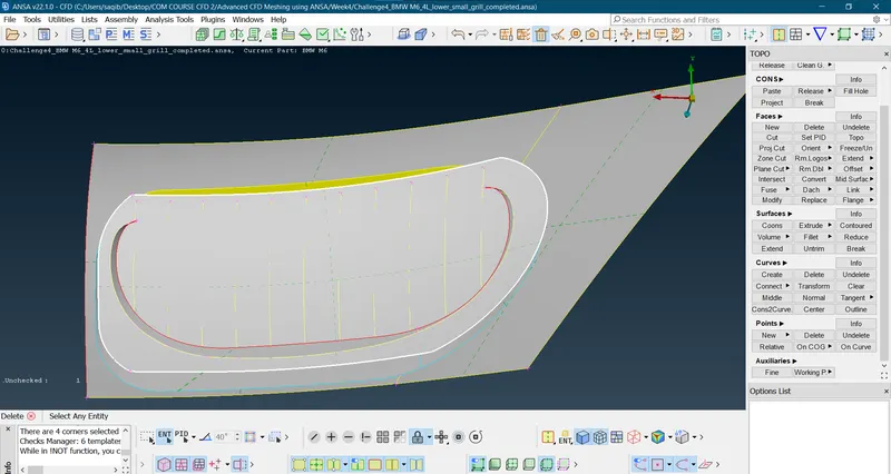
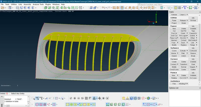
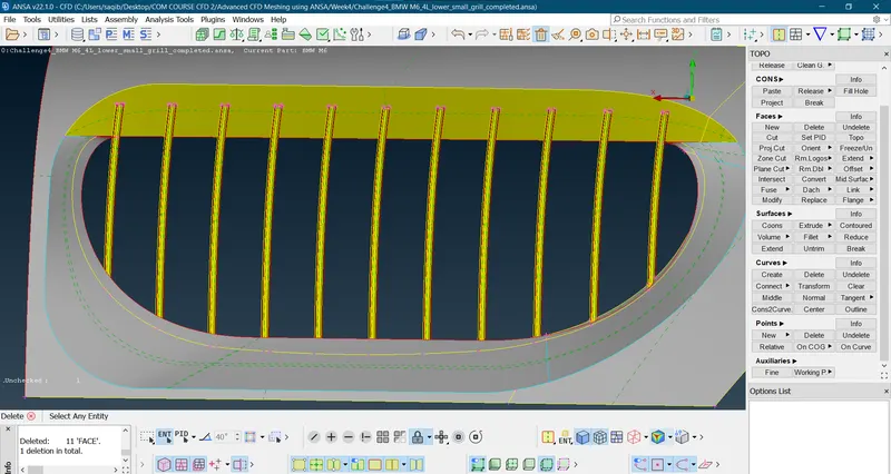
- As there is no need for the plate so deleting it.
- Delete any unwanted surfaces:
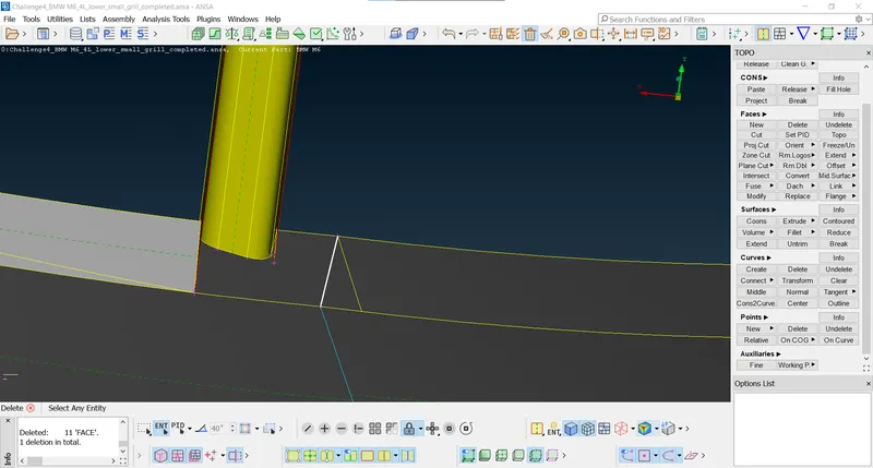
- Perform the cut opteration on the base of the fins to get only the needed surface.
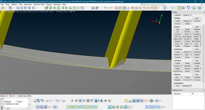
- Delete the surface as interferece in the construction and create the new surface and cut:
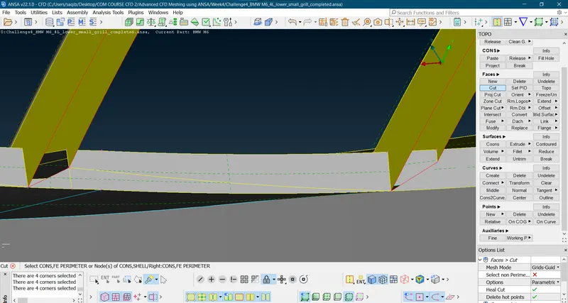
- After deleting the cut surfaces as they are not useful;
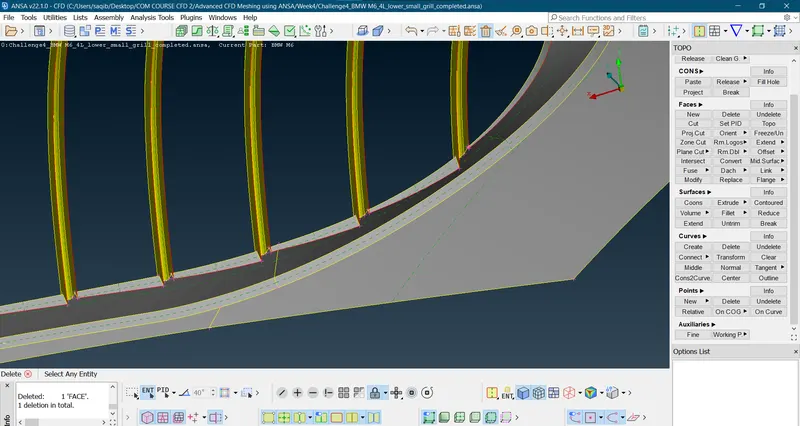
- Now create the surfaces between the fins:
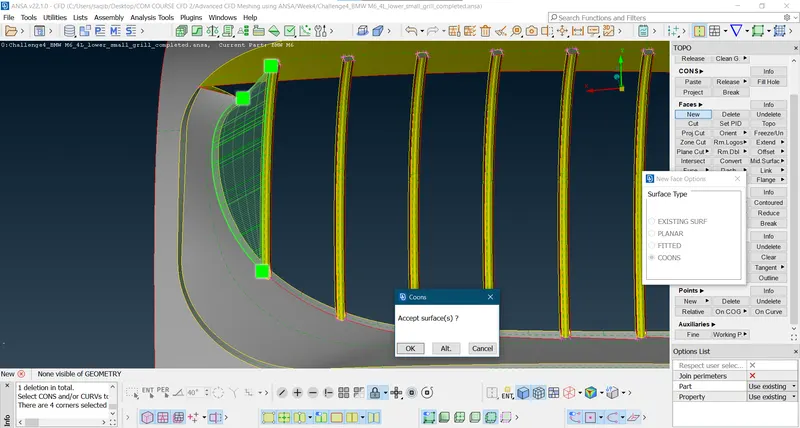
- Eleminating the unneccessory parts of the fins:
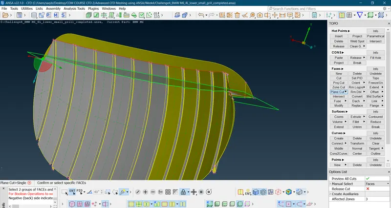
- Use the plane cut and select the three points on which the cut will occur(add a hotpoint in the middle).
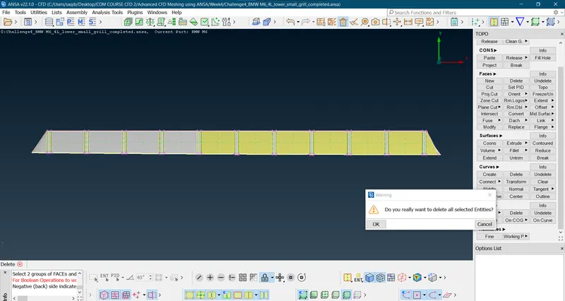
- And delete the unwanted upper surface:
- Now cover the inner open surface:
- Since project hot points command is not giving the desired results hotpoints are inserted manually:
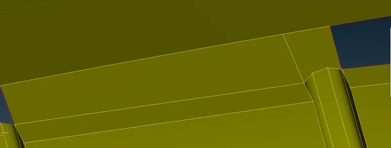
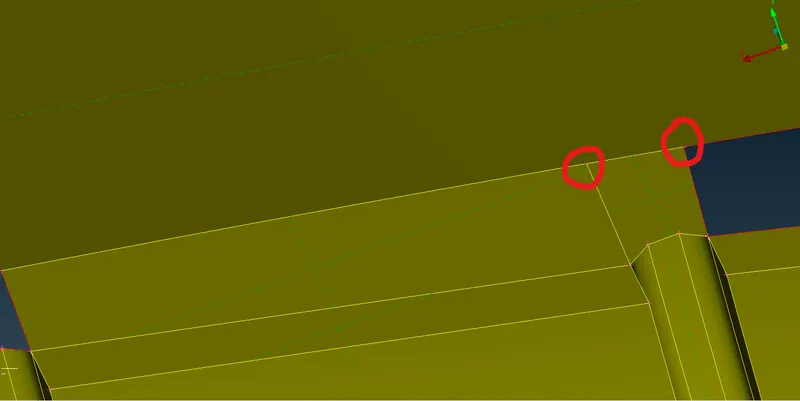
- As this is giving the appropriate results, will continue further.
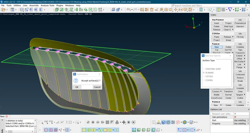
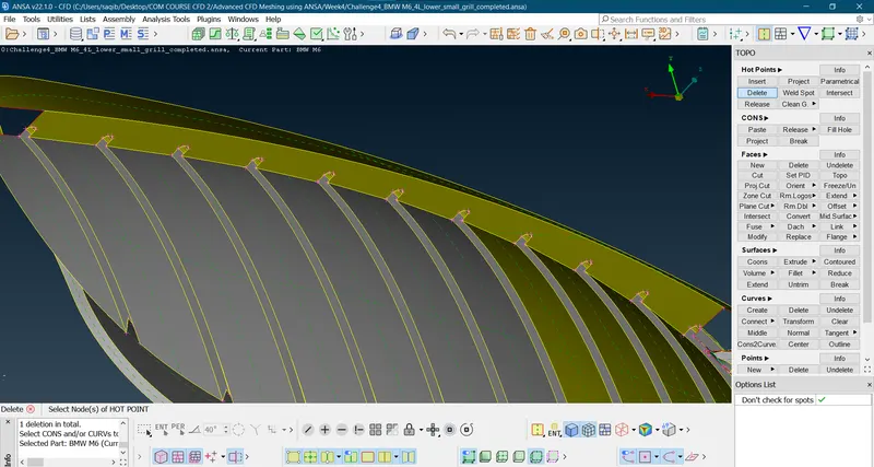
- Deleeting the surface after using intersect command:
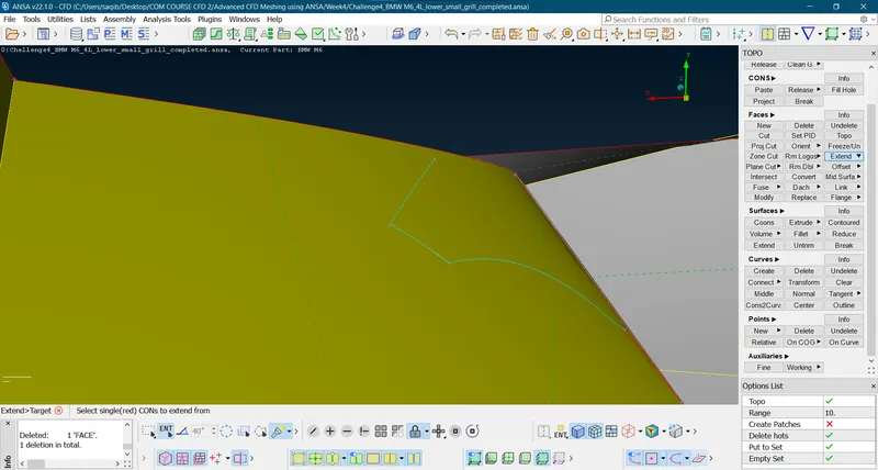
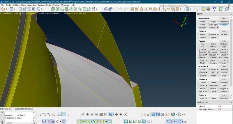
- Here first the intersecting surfaces are deleted and coons2curve command is used to convert the top surface coons to the curve for making new surface.
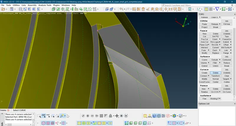
- The surfaces are closed keeping the needle cons to minimum so to avoid any deformation during the meshing.
- Fixing the otherside:
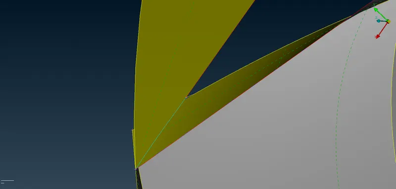
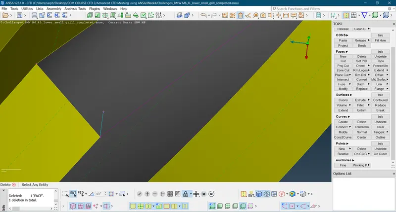

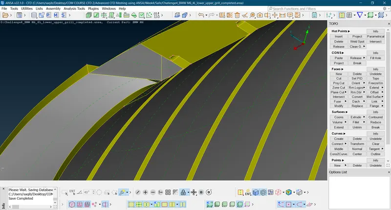
- Closing the surfaces and running he geomety check.
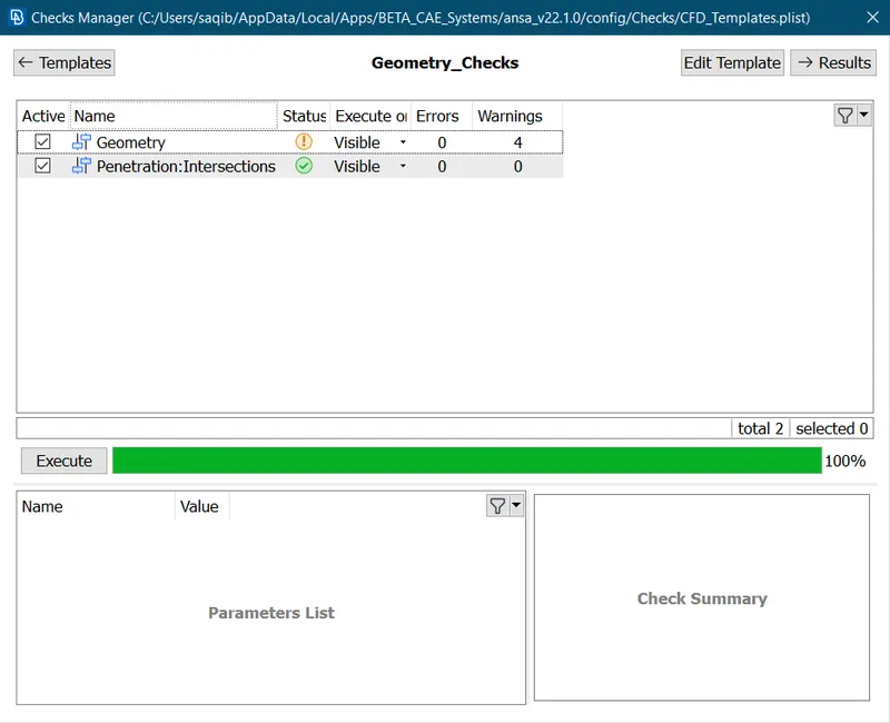
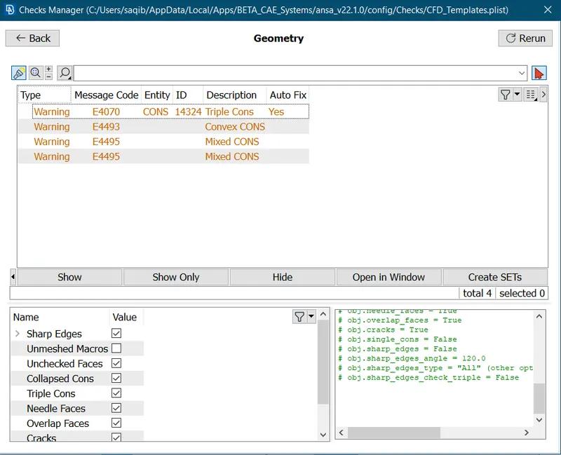
- Head light: We require only the external part of the head light, so we will delete the all un wanted inner parts so to reduce the mesh count and processing time.
- Cleaning:
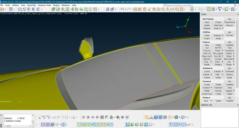
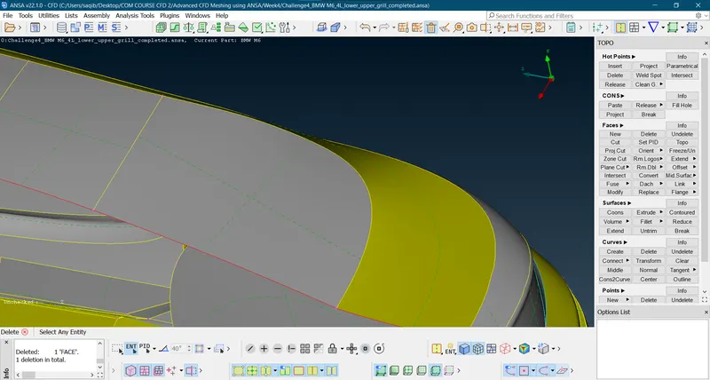
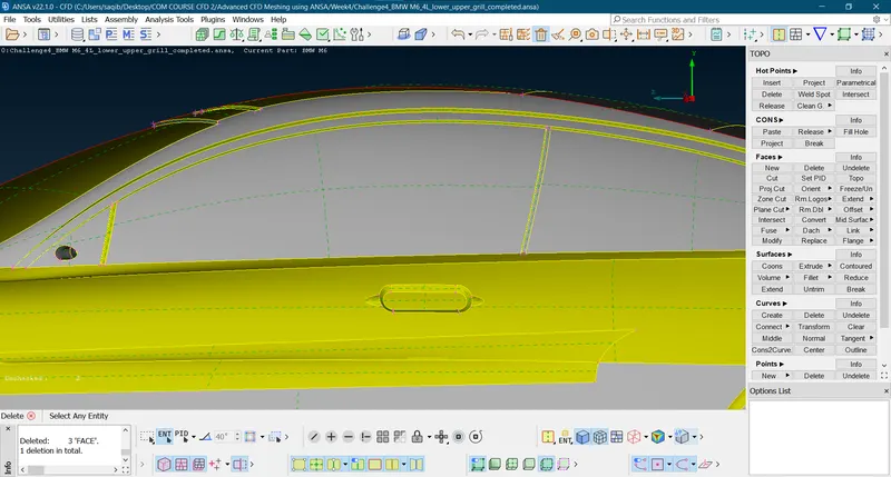
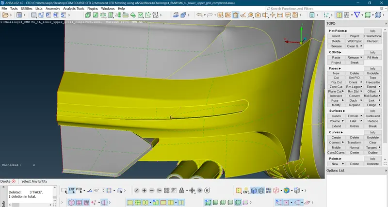
- Deleting the triple coons:
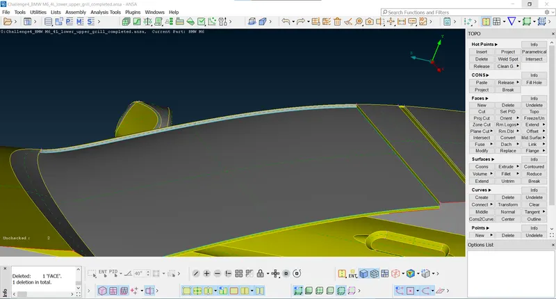
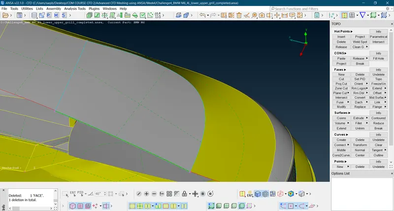
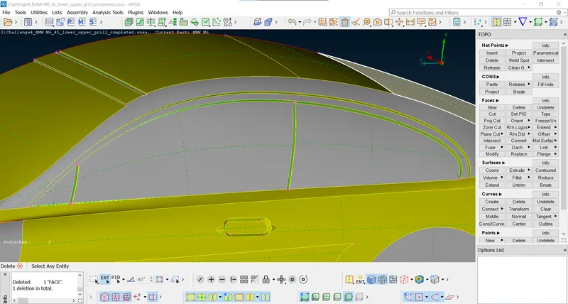
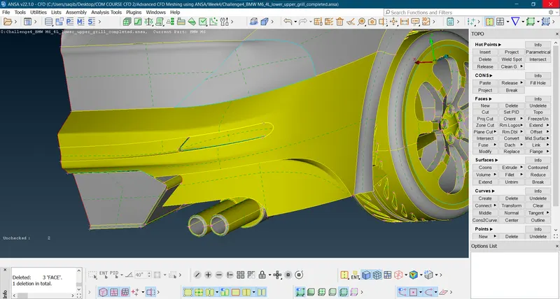
- After clearing:
- Air vents:
- As we can see there are many errors:
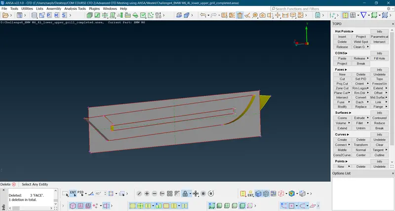
- After Intersecting and deleting the unwanted surfaces:
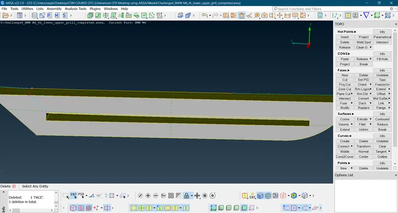
- As we can there are open surfaces that need to be closed as create hotpoints > curves > projecting curves > creating the surfaces.
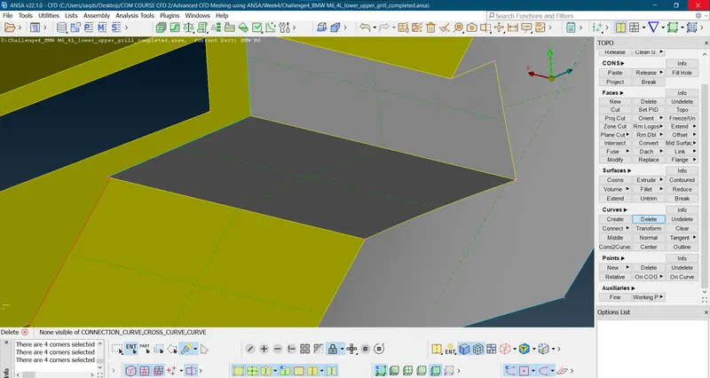
- Fixing the single coons surfaces by using the extend commnad.
- Now deleting the unwanted triple coons:
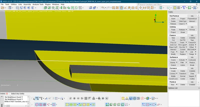
- Outwards extruding surfaces:
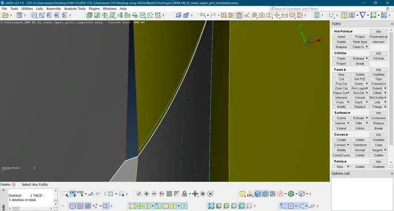
- Creating the cut and forming the new surface;
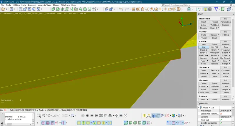
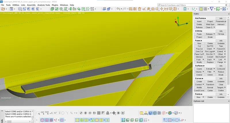
- Deleting the inner surrfaces and forming new error free surface:
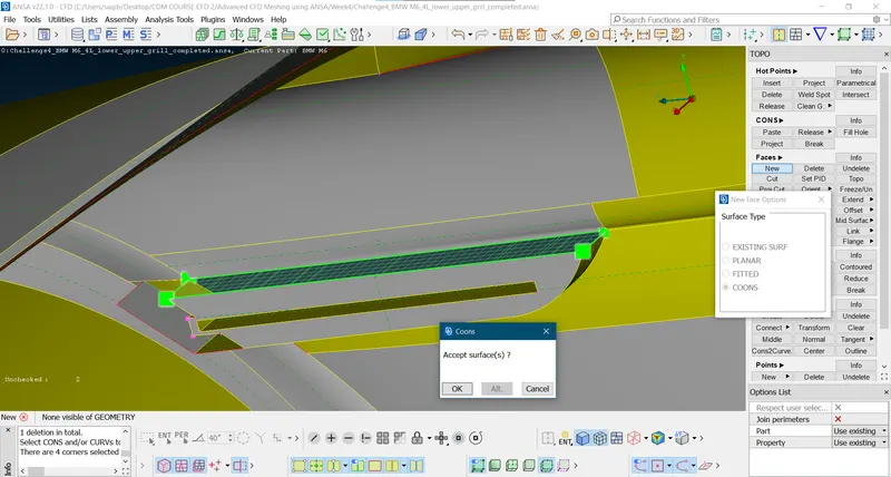
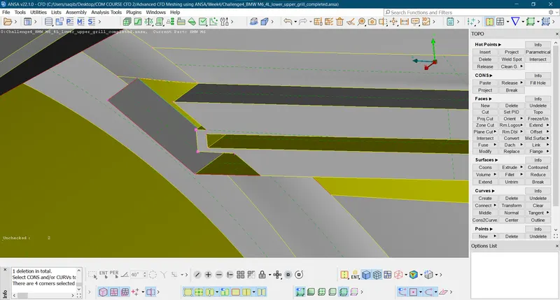
- There is an error in the faces joining so deleting and creating new surfaces to avoid errors:
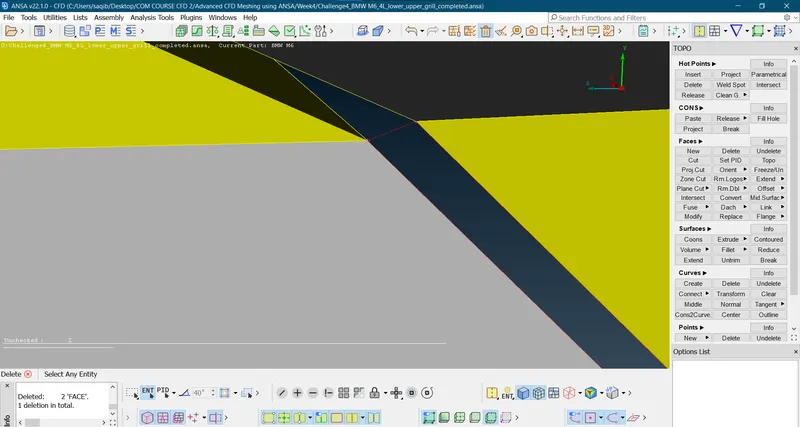
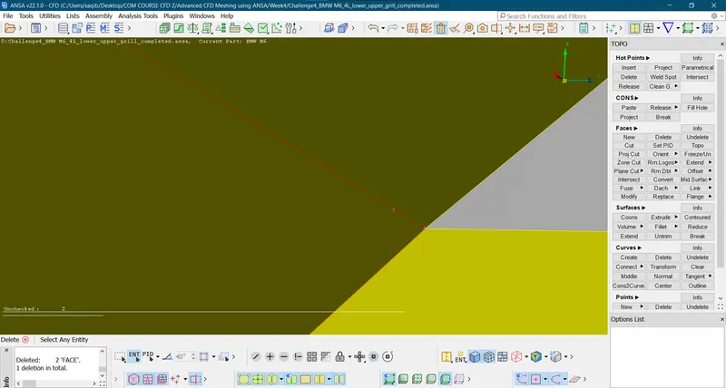
- After fixing by creating new sufaces:
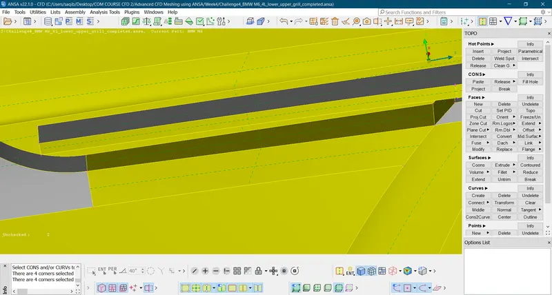
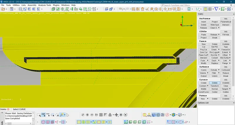
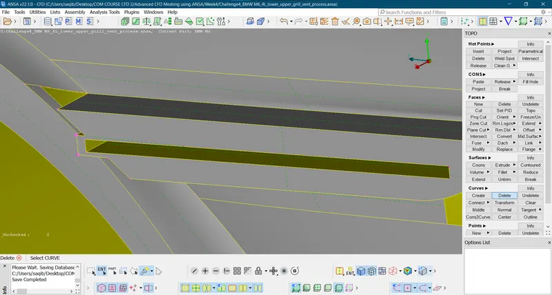
- Mud cover:
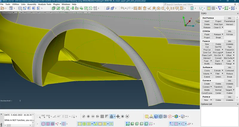
- There are some surfaces protruding in the wheel area which are unuseful surfaces hence need to delete them:
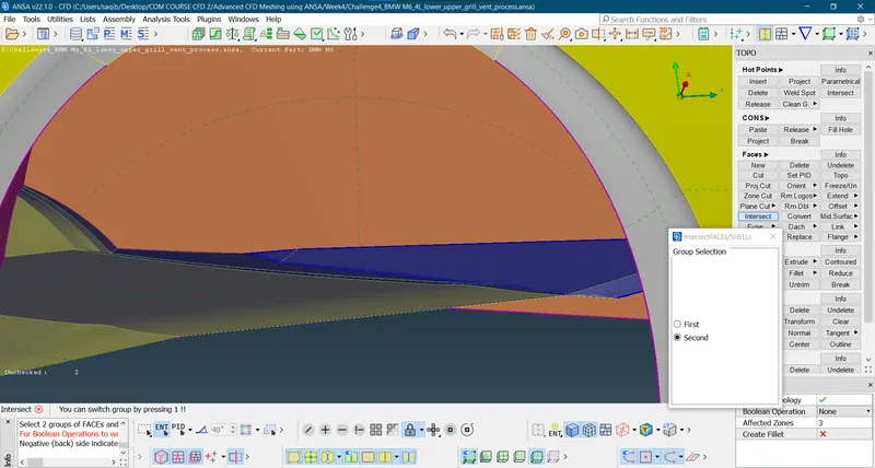
- Intersecting:
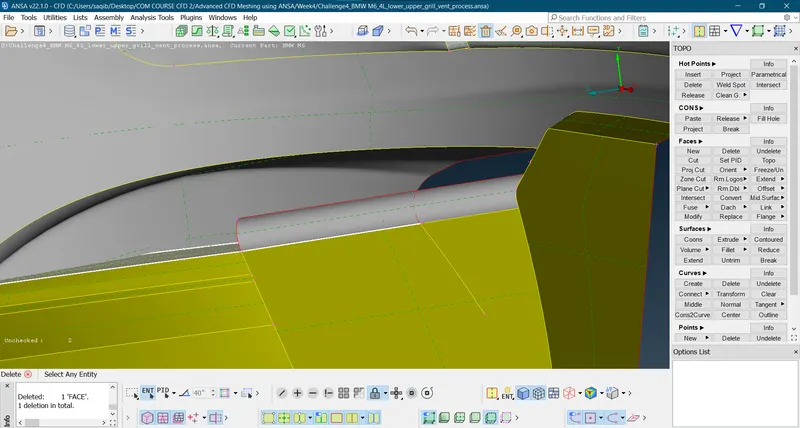
- Back bumper inner area:
- Intersecting the curves and creating the new surface:
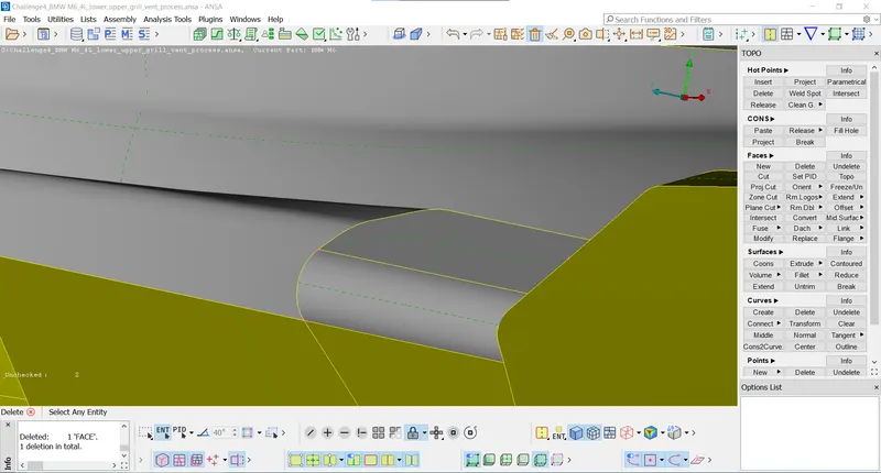
- Projecting the single coons to the surface and deleting the extra surface:
- Wheels:
- There are triple surfaces in the wheels so deleting the extra surfaces and filling the single coons formed:
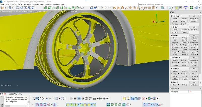
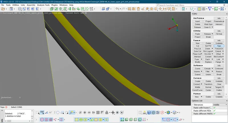
- Forming new surface:
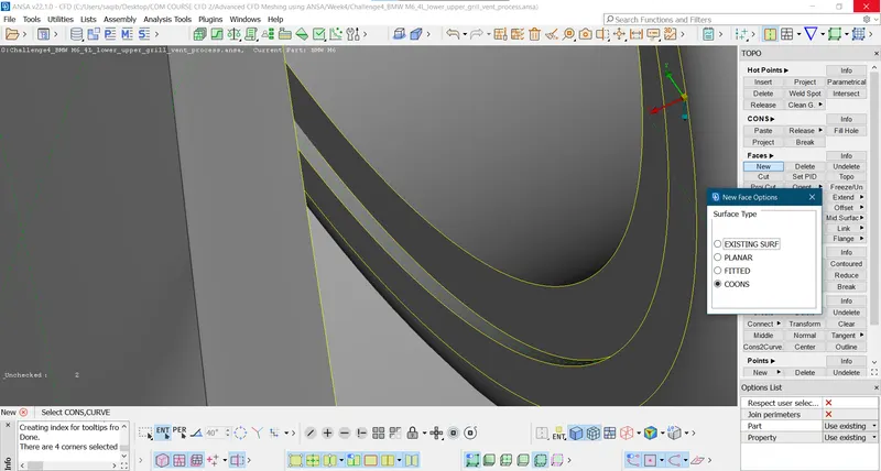
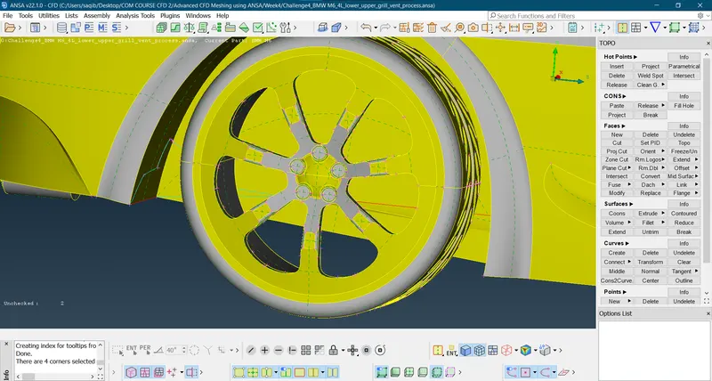
- Proceeding to the other wheel and fixing the issues.
- Clearing the floor:
- As the surface has irregularities and errors it god to delete the surface and create the new surface by capturing the coons of the surfaces using the cons2curve options and intersecting the curves:
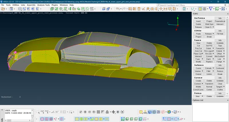
- Deleting the surfaces:
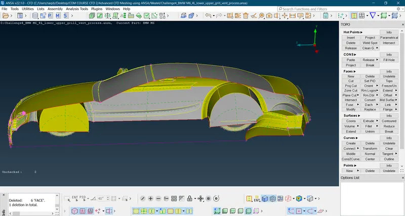
- Creating the necessary curves:
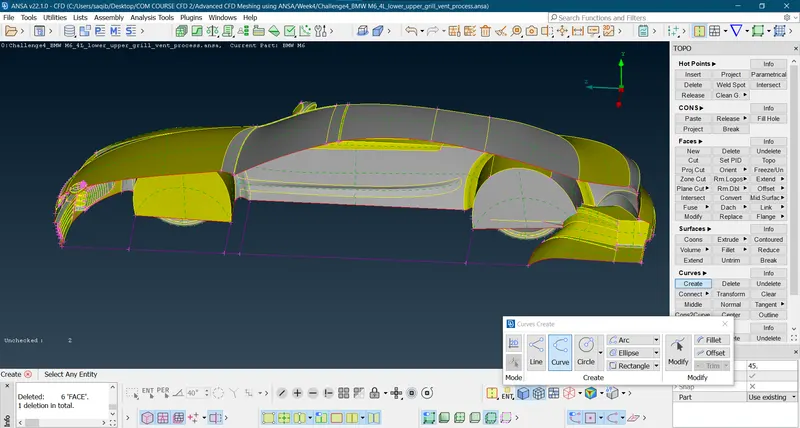
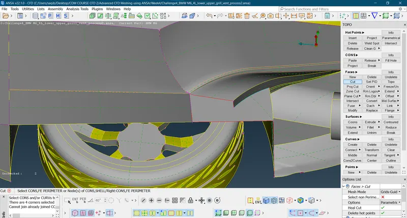
- Extending the surfaces.
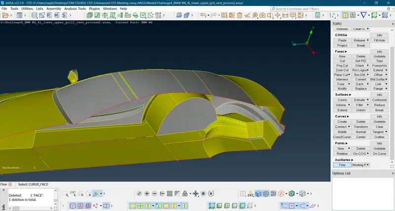
- Deleting the hanging surfaces;
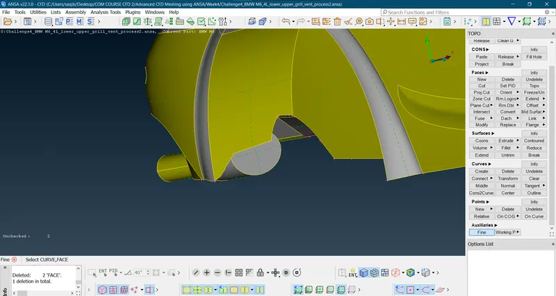
- There are two peetration issues:
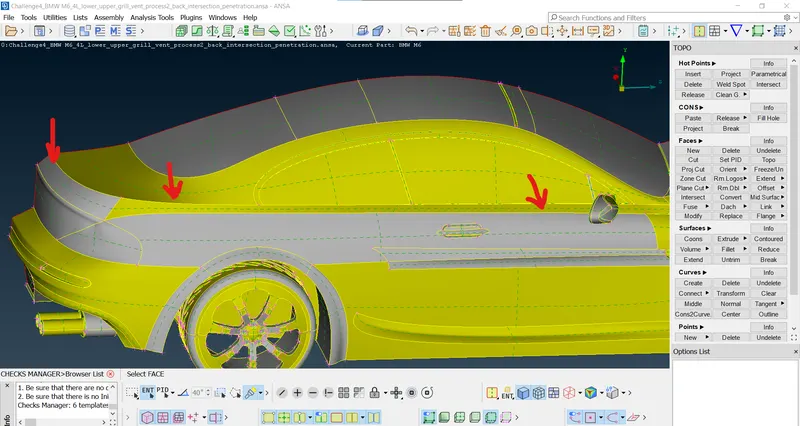
- The line represented had the penetration issue which is solved by recreating the surface.
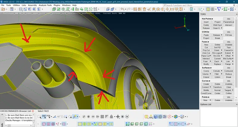
- The peneteration issue and intersection was solved by recreating the similar outer surface by using the con2curve.
- As it can be seen from the figure that all the single coons are for the outer merging body which will be mirrored later.
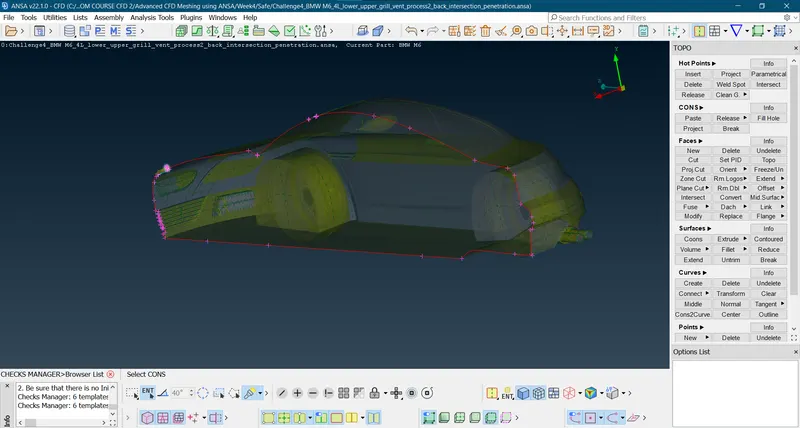
- As it can be seen all the triple coons are from the logo only which will be cleared in further moves:
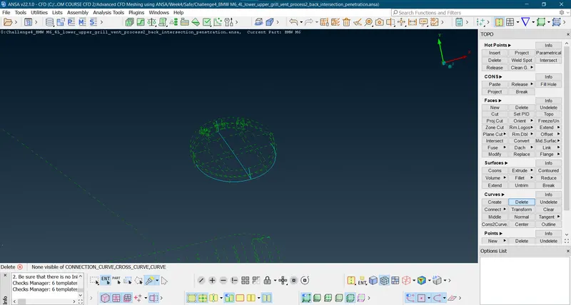
- Logo:
- Isolating the logo:
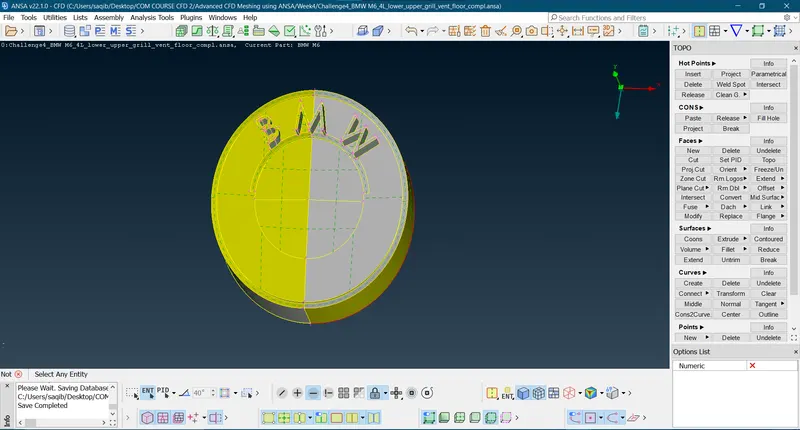
- Deleting the internal unwanted surfaces;
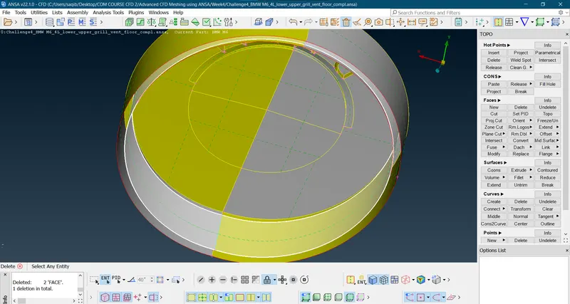
- Creating the new surface by deleting the inclined saurface:
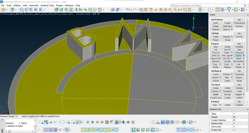
- Extending the surfaces:
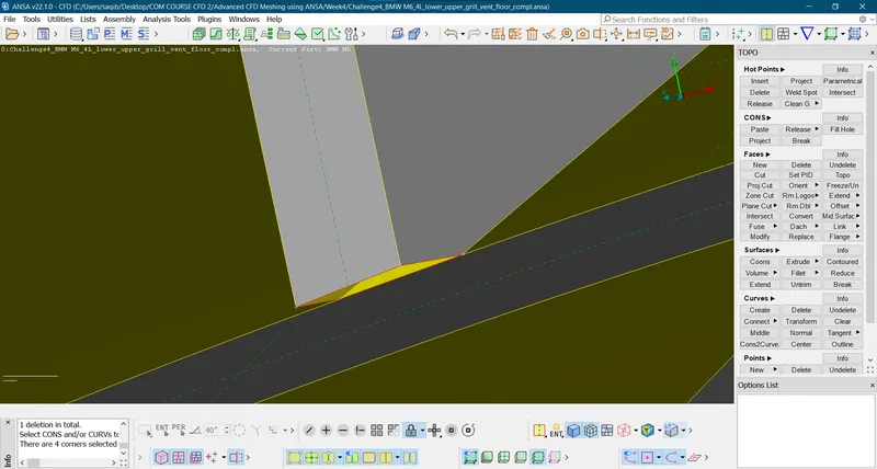
- After clearing the inrtersection parts:
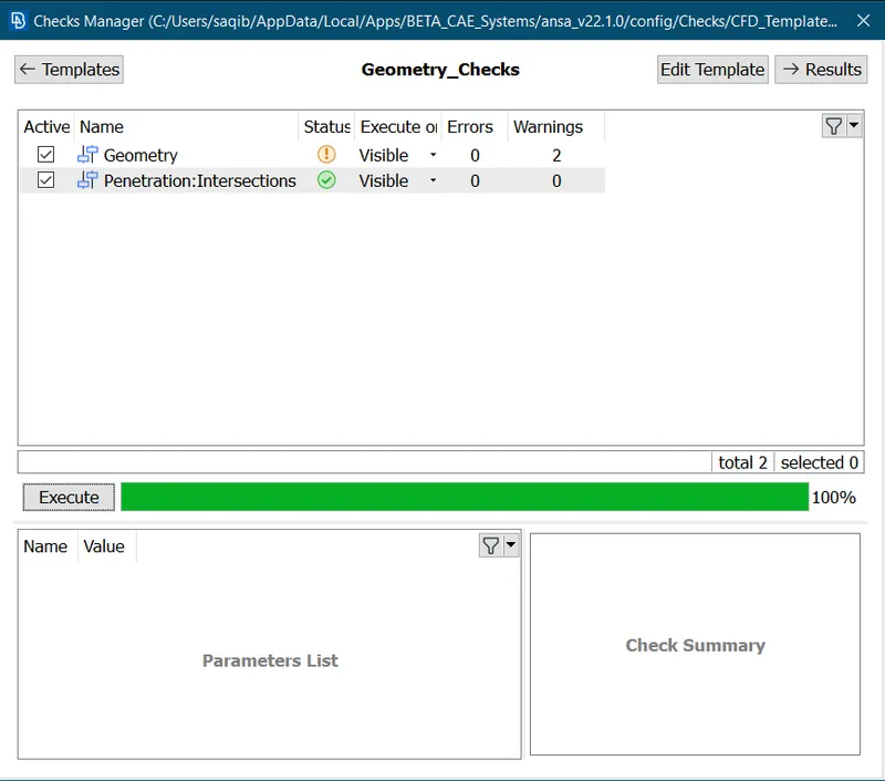
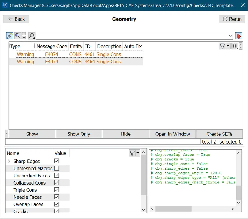
- Here to delete the intersecrtion we created a new surface and using the project command we projected single coons to the surface and deleted the unwanted surfaces.
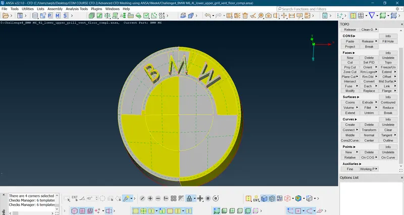
- After clearing the logo just project the coons to the bonnet:
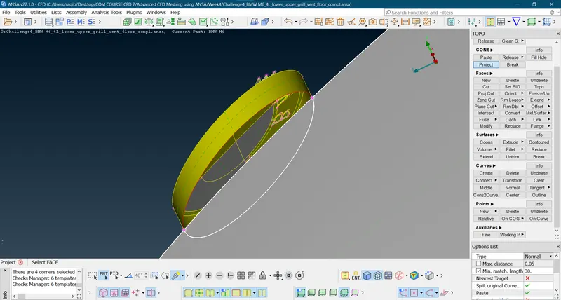
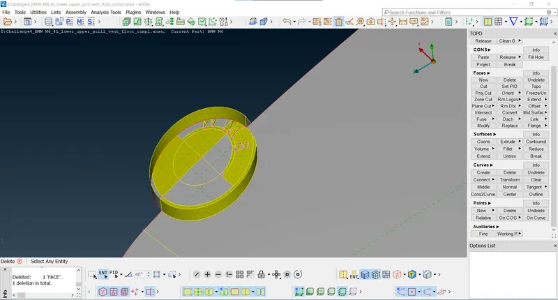
- After cleaning:
- Silencer;
- There are repeating surfaces:
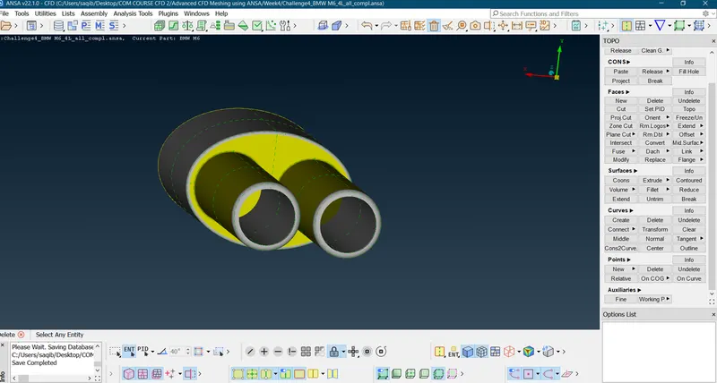
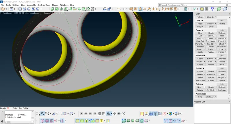
- After cleaning:
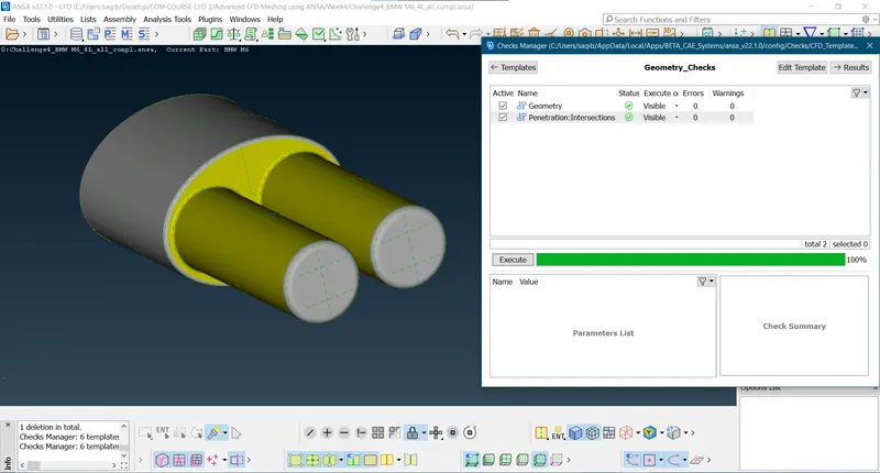
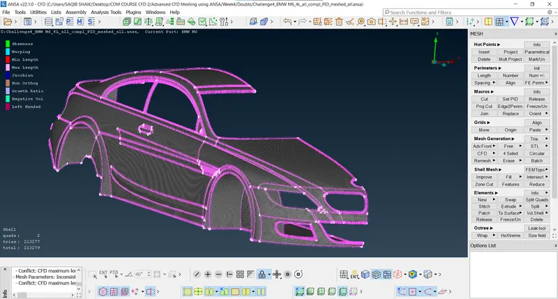
- After cleaning the whole geometry model:
- Single coons present are only of the mirroring side:
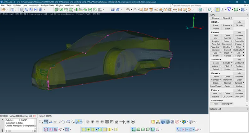
- There are no penetration issues:
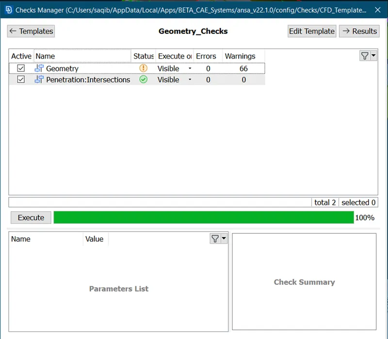
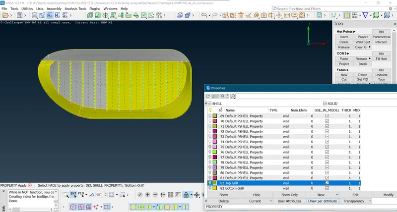
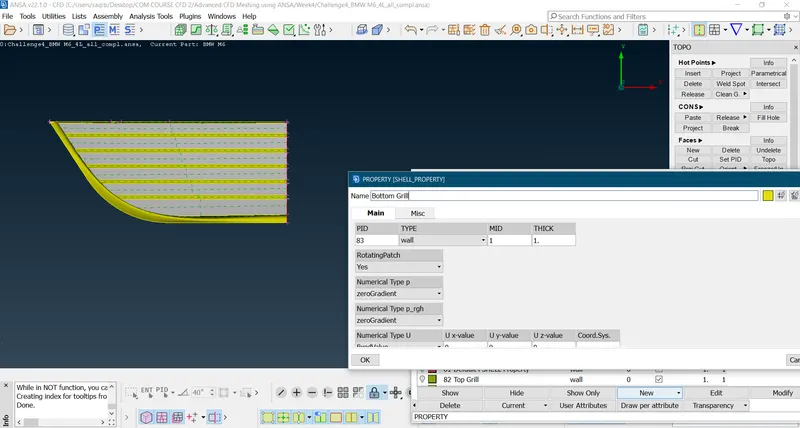
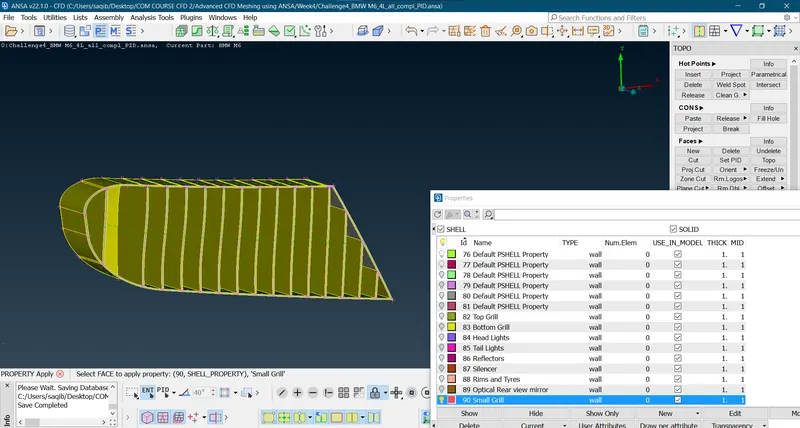
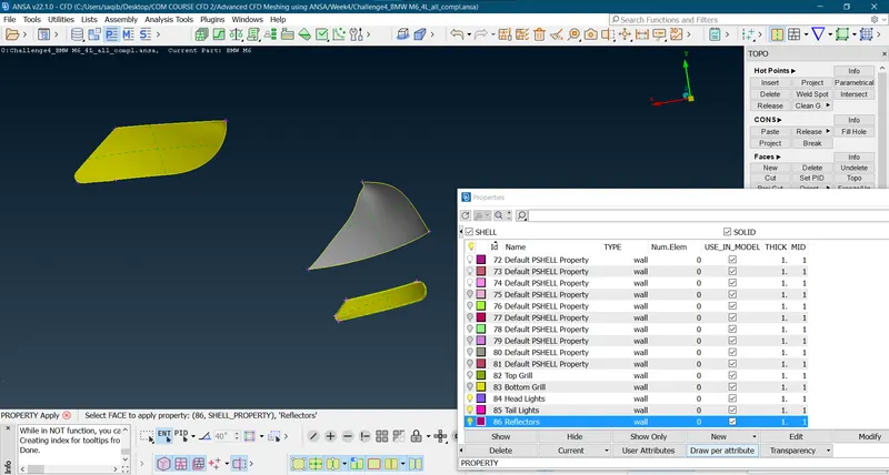
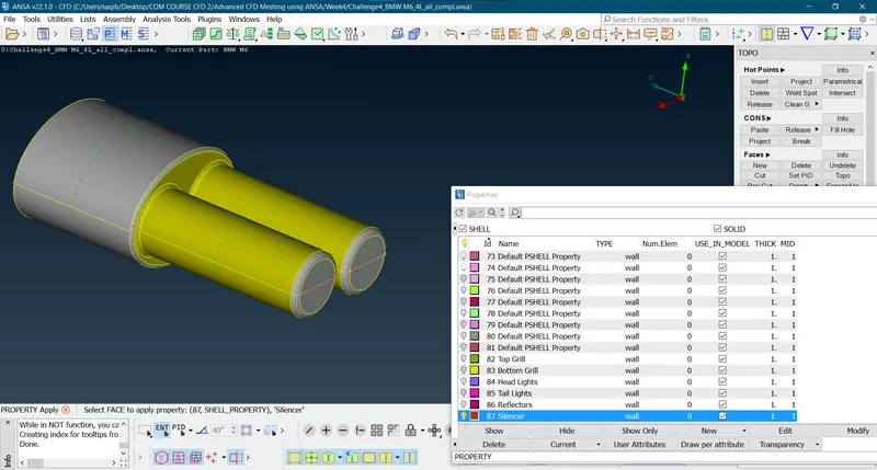
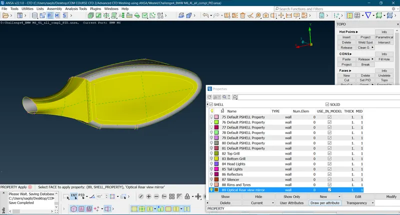
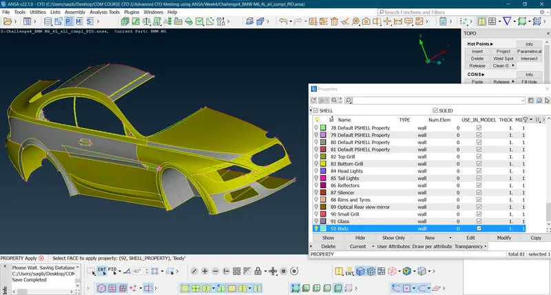
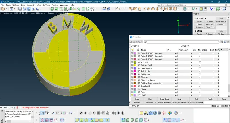
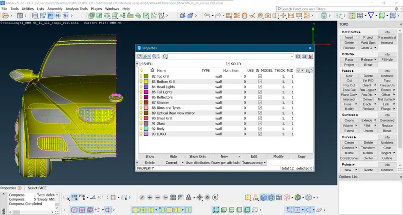
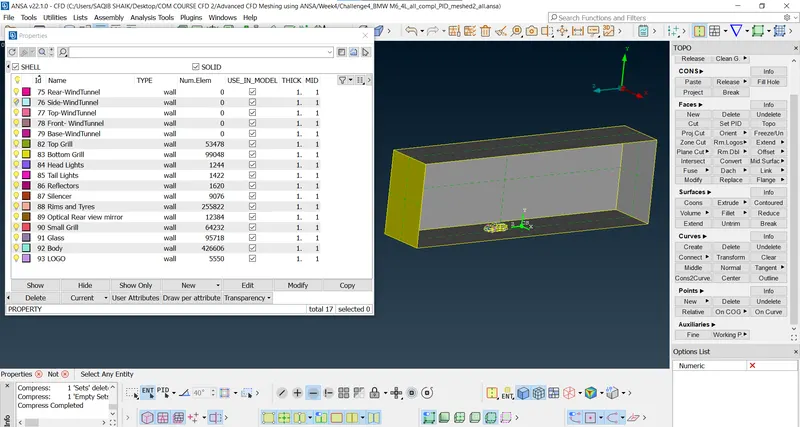
- Now naming the PID's:
- PID's > Create New > Shell Property > Apply > geometry > Middle click.
- Top Grill:
- Bottom Grill:
- Small Grills:
- Head Lights, Tail Lights and Reflectors:
- Silencer:
- Optical Rear View Mirror:
- Body:
- LOGO:
- Top Grill:
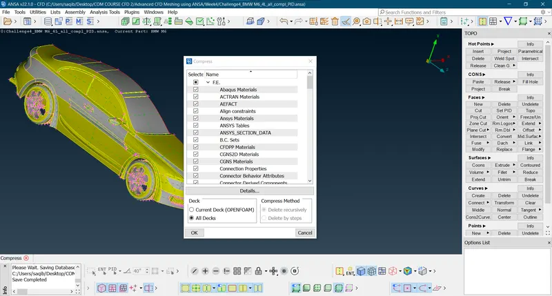
- Now compressiong to remove the unwanted/Repeated PID's:
- Meshing:
- The specifications and quality parameters for the meshing are given in the description:
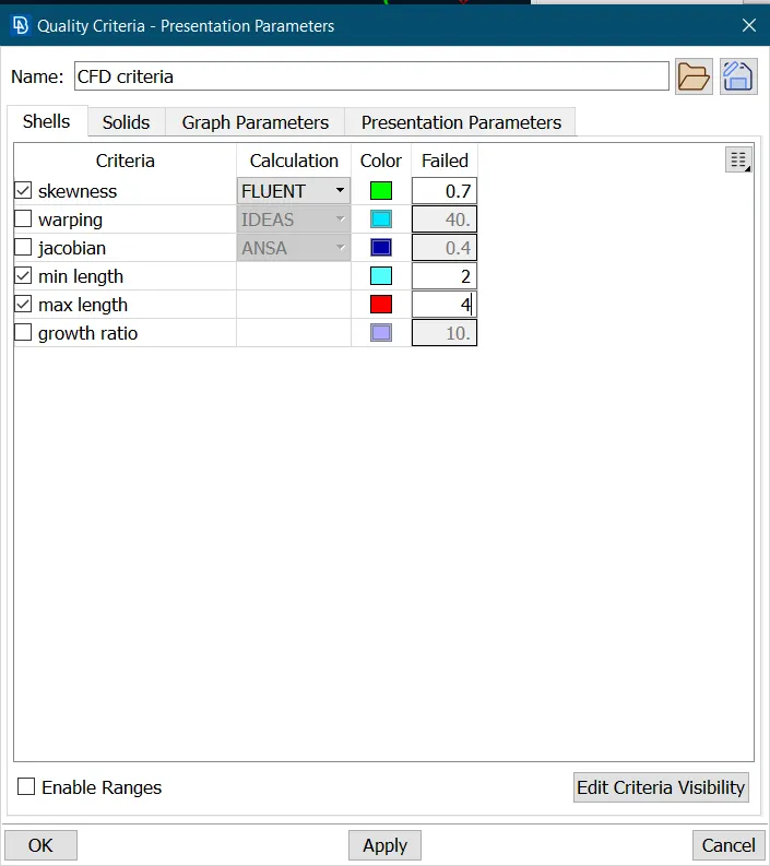
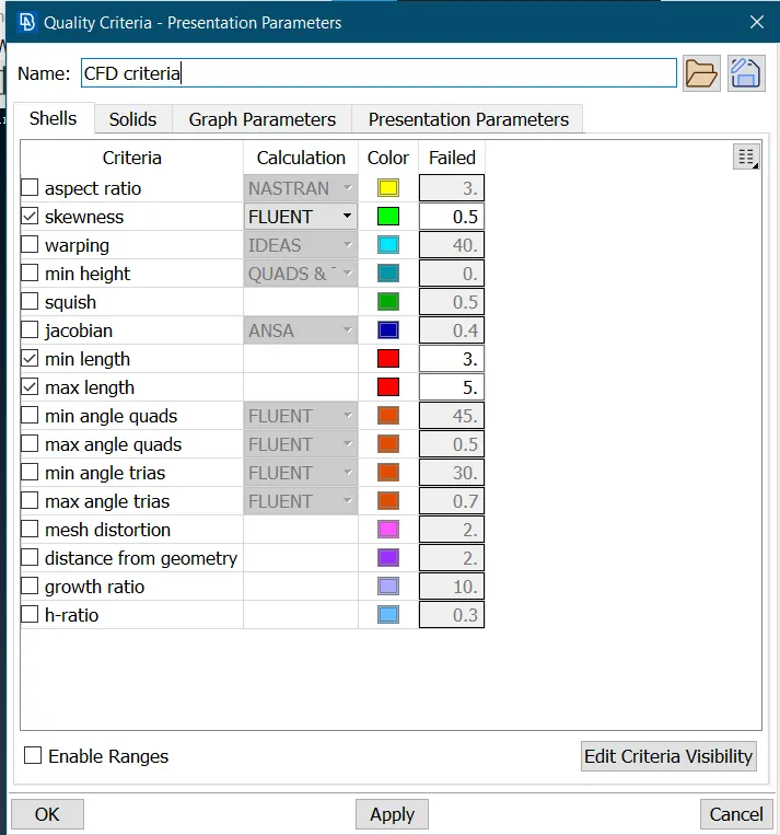
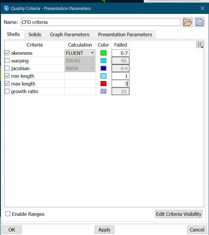
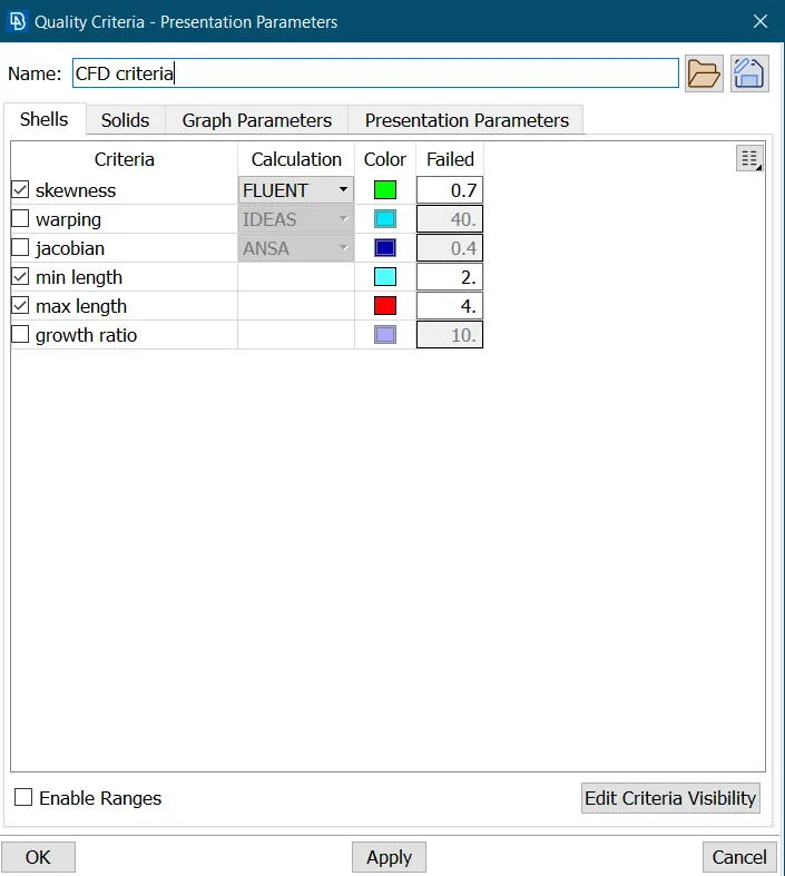
- Selecting the quality criteria, as in CFD meshing done here we are only concerned about the skewness, minimum and maximum length of the node elements, so select that and deselecting all others:
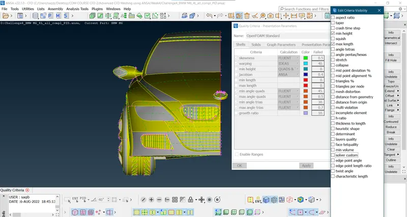
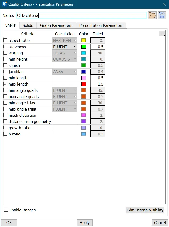
- Selecting the fail parameters, these shows up when the element is not in accordance with the given value:
- These will indicate as fail if the element node length goes below minimum target length or higher than the target length(minimun fail length must be below the minimum target length and maximum fail length should be greater than the maximum target length).
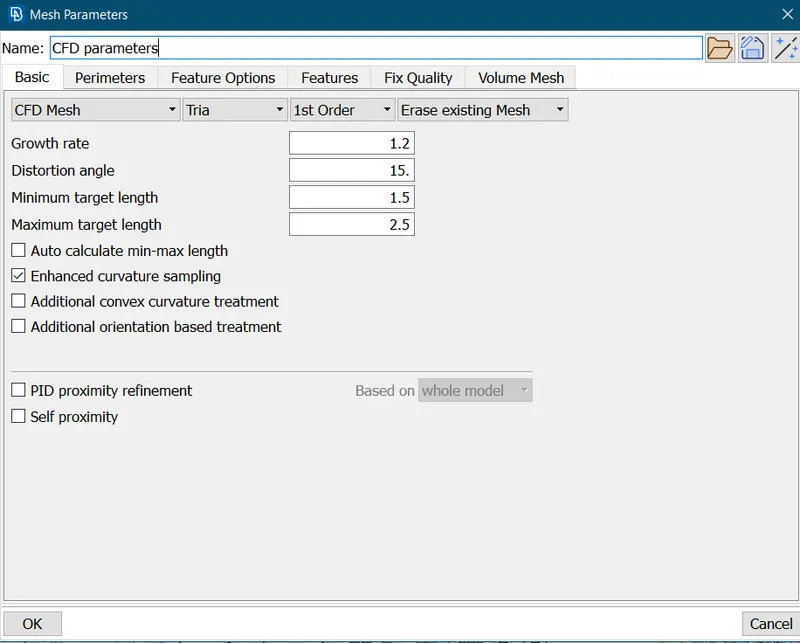
- Growth rate represents the variation or increment of the elments from the minimum to maximum defined target length.
- Target lengths for the different parts of a model and the process are mention below:
- Body - 3 mm:
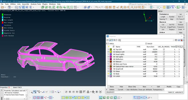
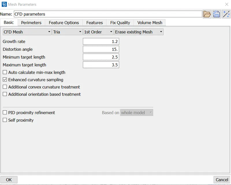
- Defining the minimum and maximum target length:
- Defining the fail criteria:
- After meshing:
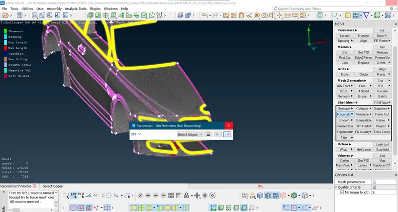
- There are many inconsistencies so doing the spot mesh:
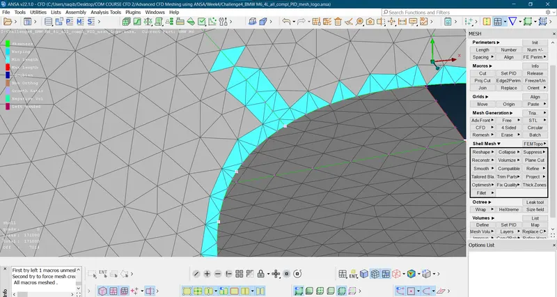
- After meshing:
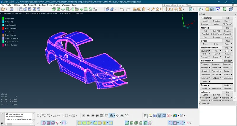
- To clear all the errors we must give the fail criteria as to suit the other PID's perimeters(as the errors are only due to the perimeter defining issues of other PID'S):
- And improve using the reconstruct option to fit the perimeters of other PID's for only the error causing parts of the body:
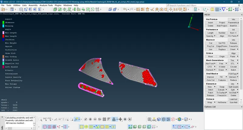
- Lights - 4 mm:
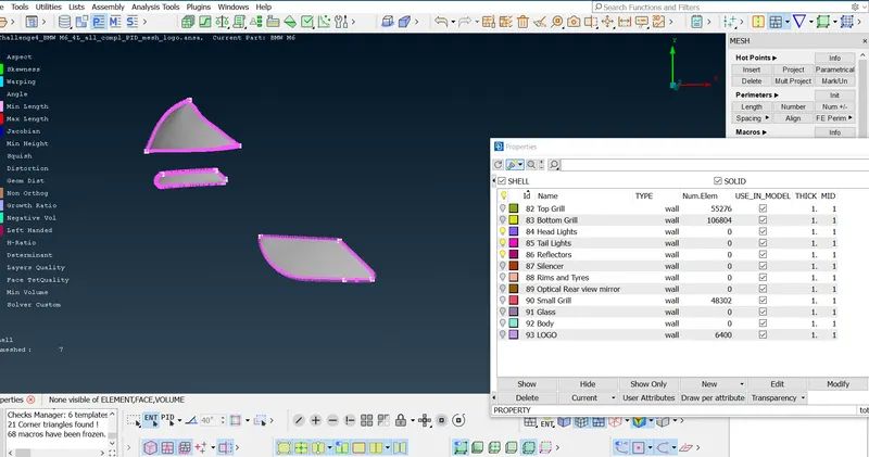
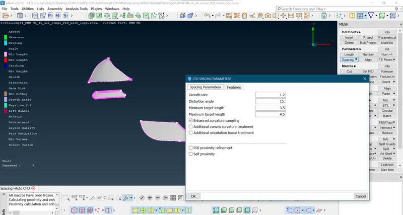
- Perimeters and Macros defining(3.5-4.5mm):
- Defining the fail conditions(3-5mm):
- After meshing there are errors so fixing them reconstruction and move command:
- Tail Light:
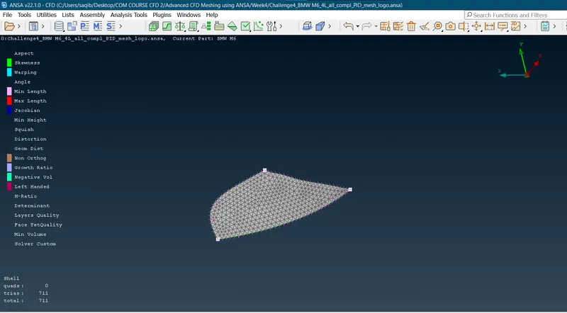
- Headlight:
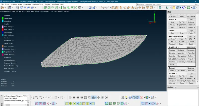
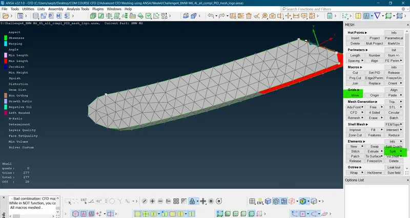
- Using the split option some of the maximim length errors are fixed:
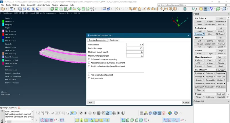
- Here for the reflector defining the parameters and macros in sizing from 2 - 3mm:
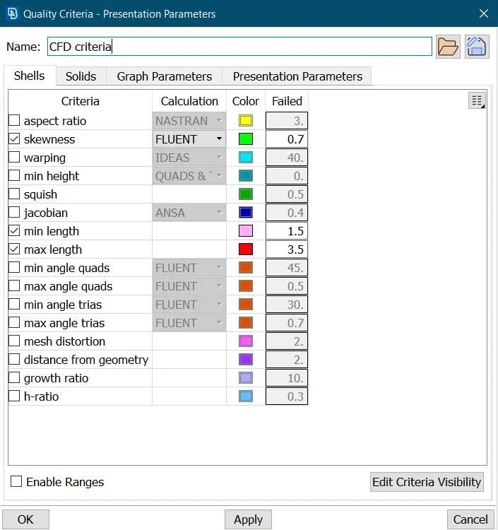
- Redefining the failed conditions.
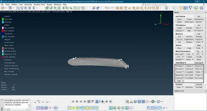
- Frezing the PID's.
- Grills - 1 mm:
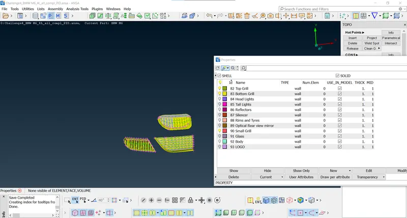
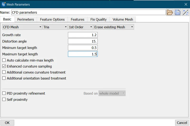
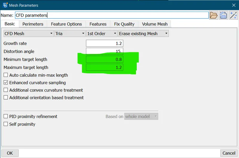
- Defining the min and max target length.
- Selecting min and max length as 0.5 and 1.5 mm resprectively.
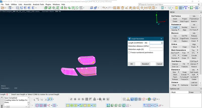
- Perimeter defining 1mm:
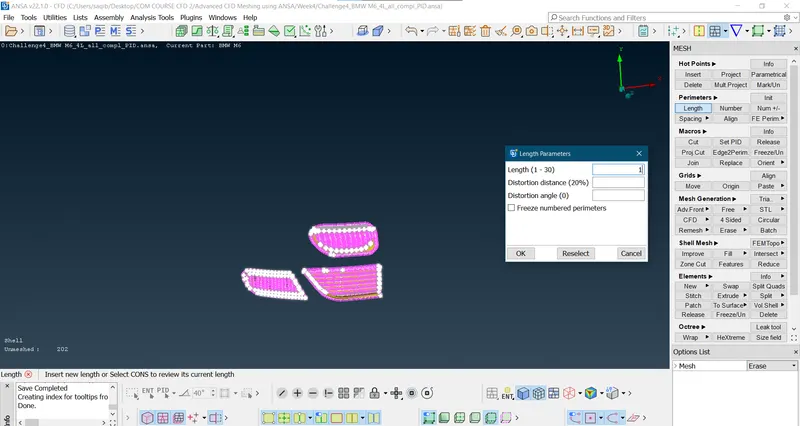
- Defining the macros 1 mm:
- Reconstructing the shell mesh:
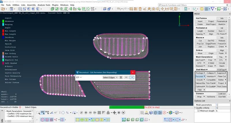
- After defining the min and max length and reconstruction shell mesh:
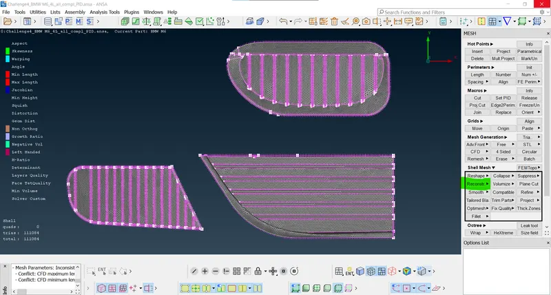
- As the mesh failed and our objective is for external aerodynamic analysis we move to the CFD mesh:
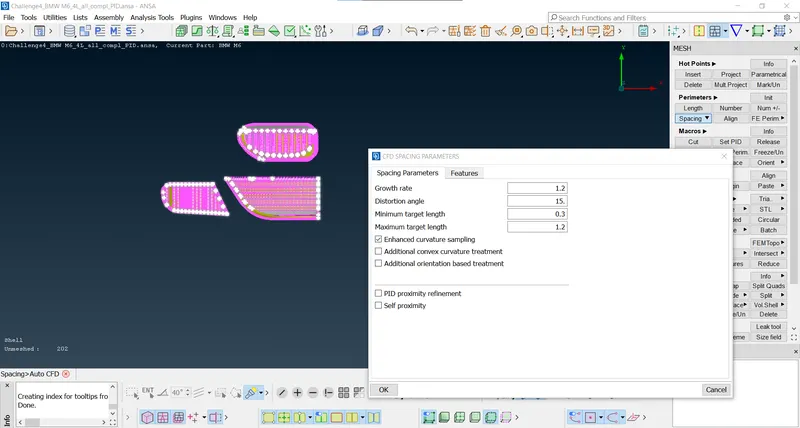
- Spacing > Auto CFD > Perimeter(define) > Macros(define).
- Perimeter define(0.3-1.2):
- Macros defining(0.3-1.2):
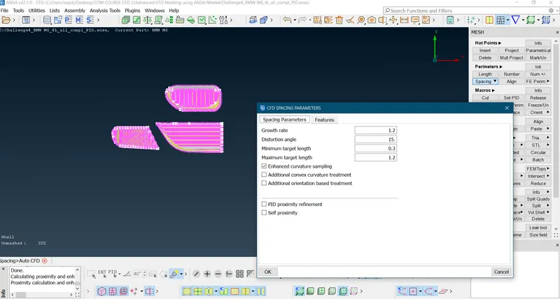
- Now mesh using the CFD in mesh tool bar for the visible parts.
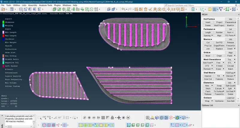
- After reconstructing the 92 OFF elements are fixed:
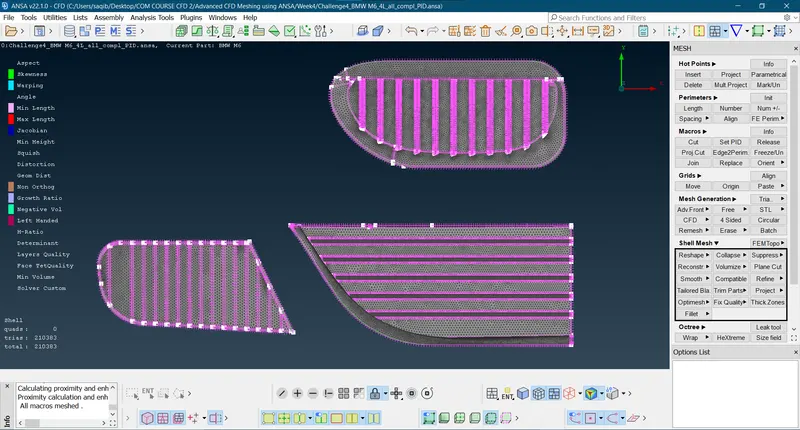
- Now freezing the meshed components:
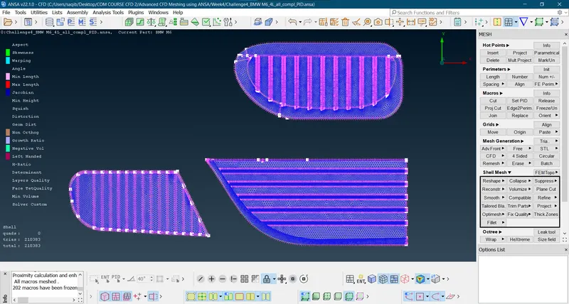
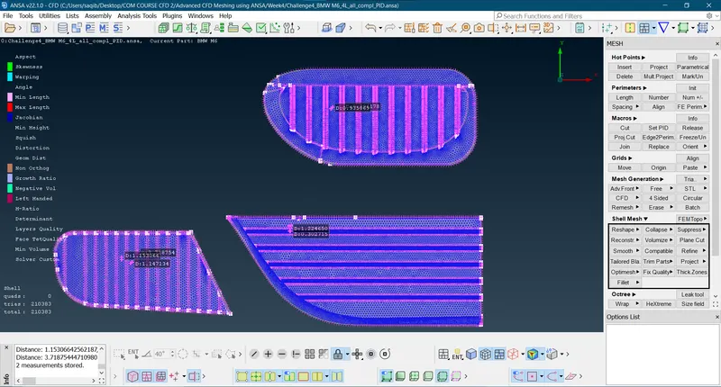
- The elements are within the target length specified.
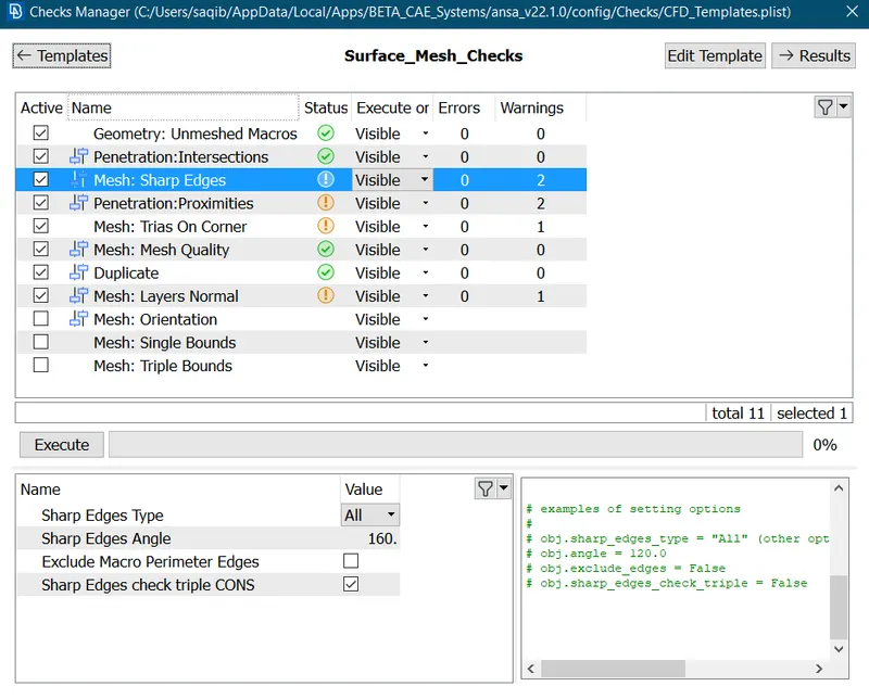
- As surface mesh checks show no errors we can proceed to the next PID.
- Rims and Tyres - 2 mm:
- Isolating the Tyre and Rims PID:
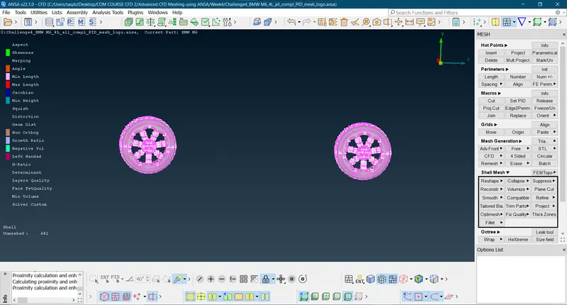
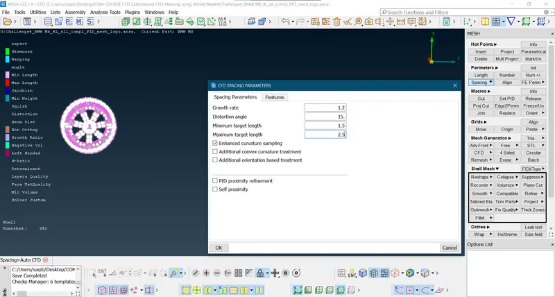
- Defining the parameters and macros in the spacing from 1.5 - 2.5mm:
- Defining the fail conditions(1mm-3mm):
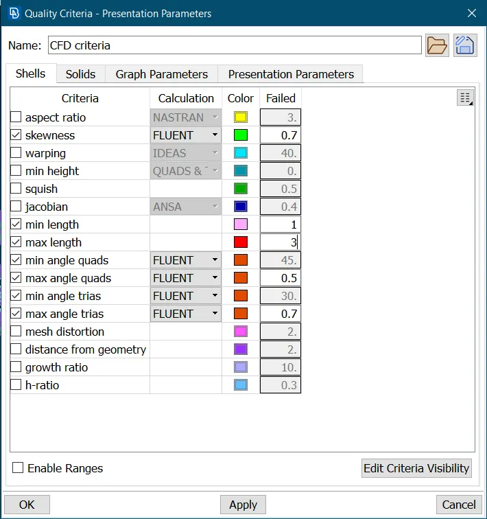
- As the element target length is specified for 2 mm it is higher or sometimes double the area/length of the elements so there will be some error for the criteria:
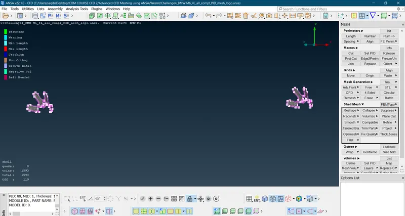
- It is OK as they are small length errors caused due to small areas in the rim, if we try to correct them the outline geometry is disrupted so keeping them as it is as instructed.
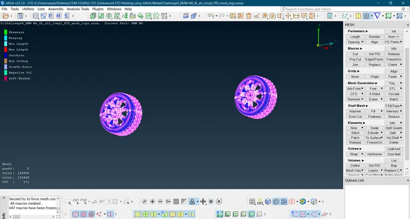
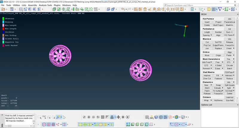
- The results are obtained after fixing the issues and stoping when the geometry gets detoriated by solving the issues.
- Any further fail solving will result in the geometry detoriation:
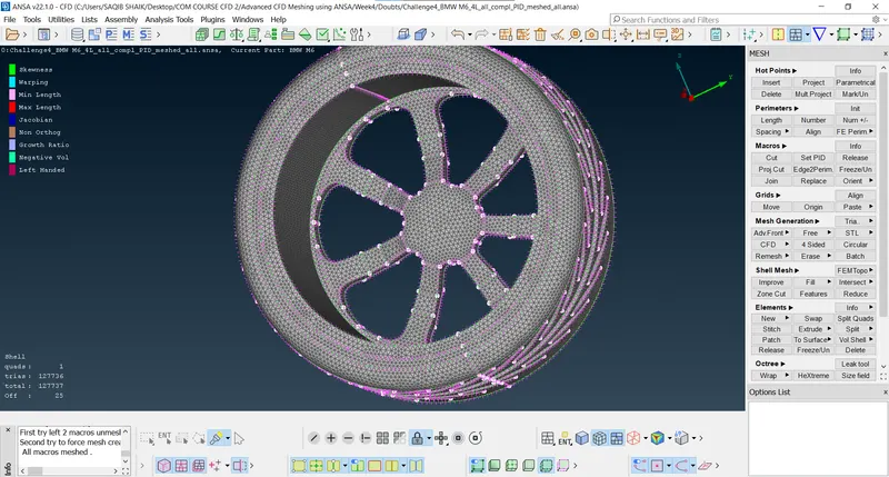
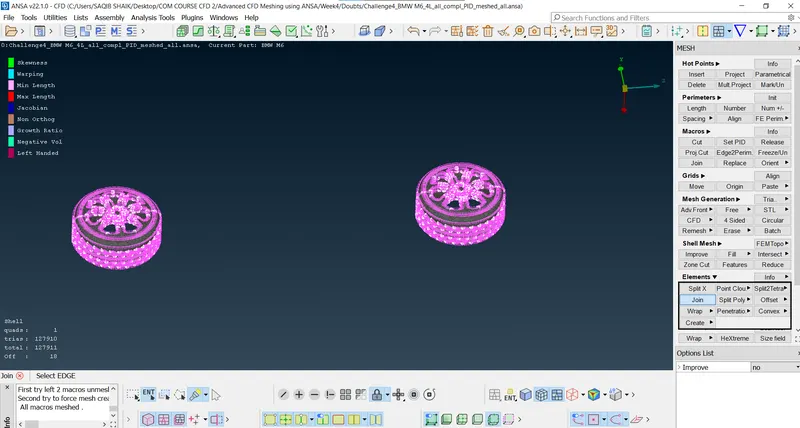
- The fail alerts are confined to 18.
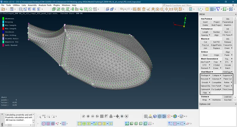
- Optical Rear view mirror - 2 mm:
- Slecting the PID:
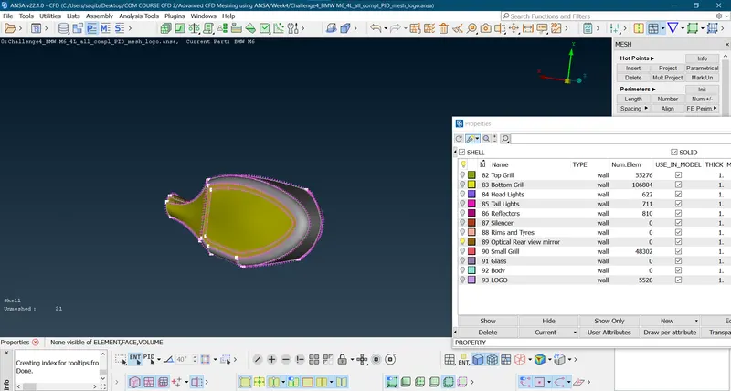
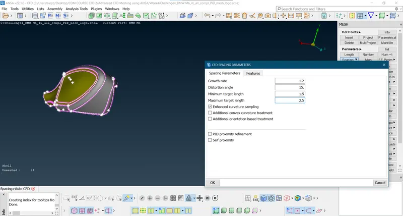
- Defining the parameters and macros from the spacing for CFD(1.5mm-2.5mm):
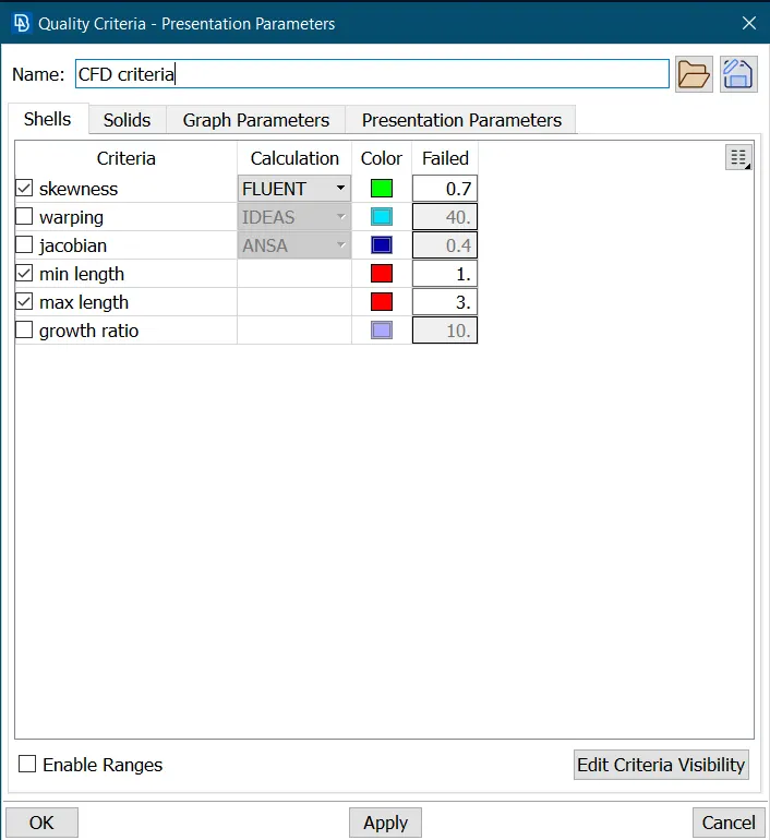
- Selecting the fail criteria conditions and defining(1mm - 3mm):
- After meshing and reconstructing:
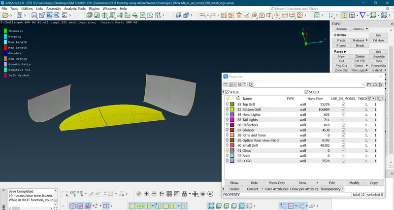
- Window - 2 mm:
- Defining the fail criteria:
- Defining the minimum and maximum target length:
- After meshing:
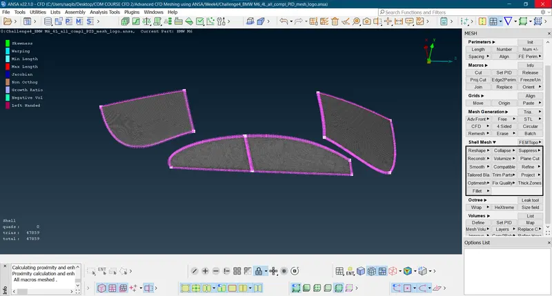
- After the meshing freezing is done.
- Silencer - 3 mm:
- Defining the target length:
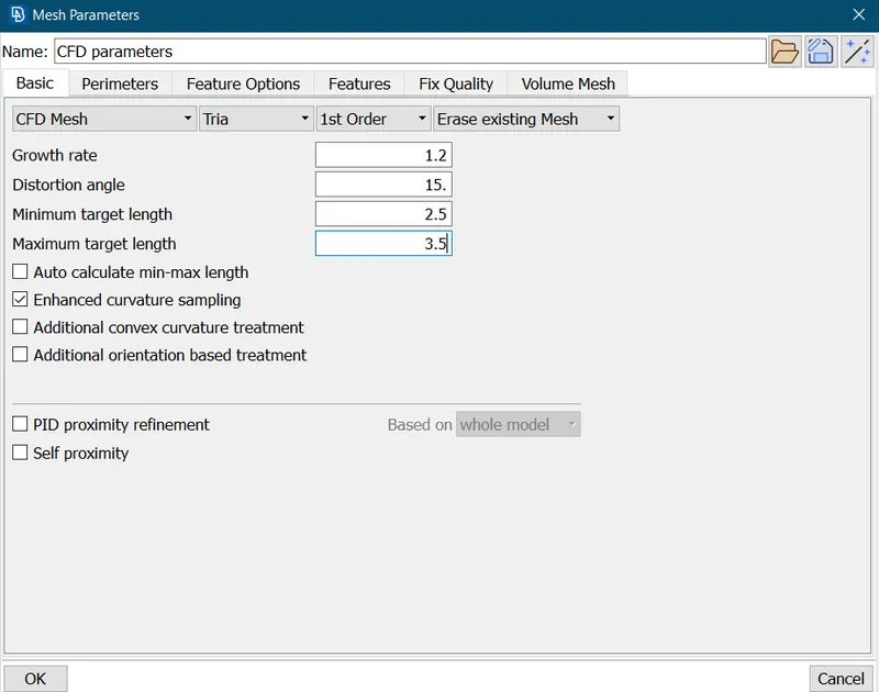
- Defining the fail criteria:
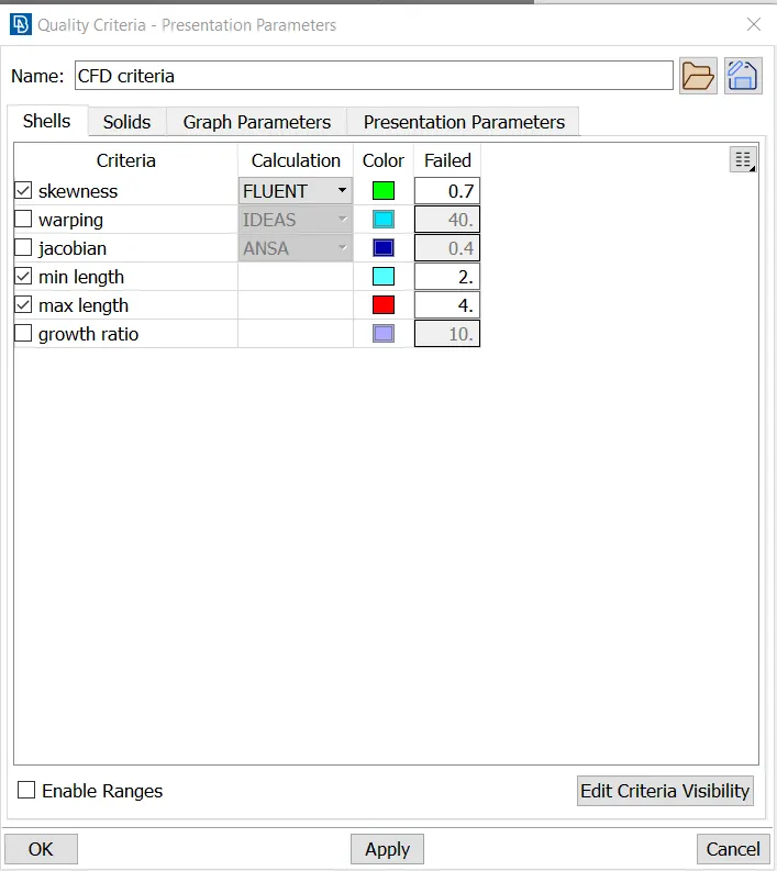
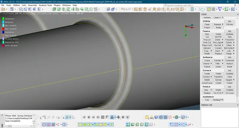
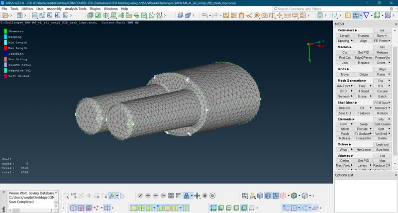
- Uncutting the edge by manintaing the geometrical shape of the silencer as some the elements in the silecncer are below the minimum target length which will fail due to the minimum fail length(2 mm).
- After meshing and reconstructing:
- Defining the fail conditions:
- Logo - 1 mm:
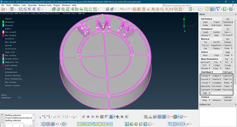
- Perimeters defining(0.3-1.2mm):
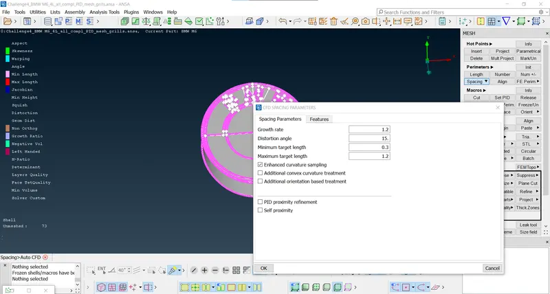
- Macros define(0.3-1.2mm):
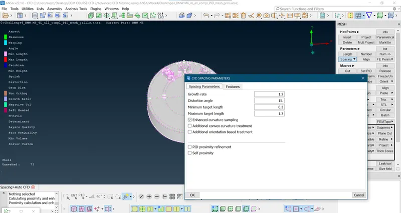
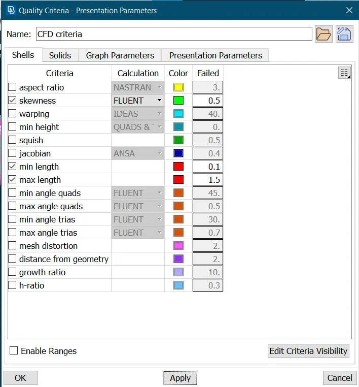
- Skewness was adjusted to 0.7.
- After meshing with CFD preset and reconstructing there are no errors:
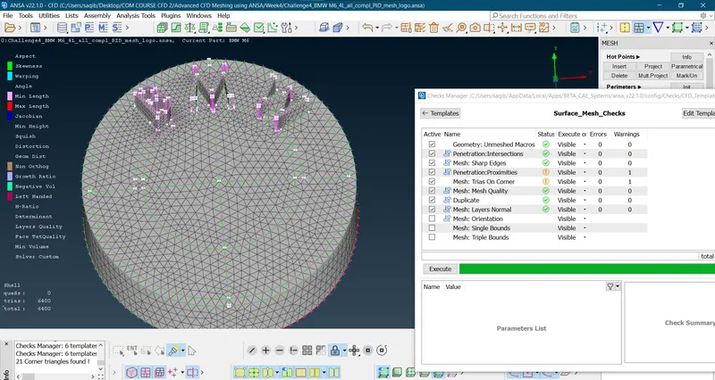
- After this freezing the PID LOGO.
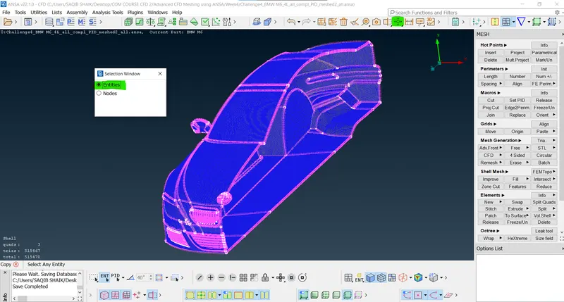
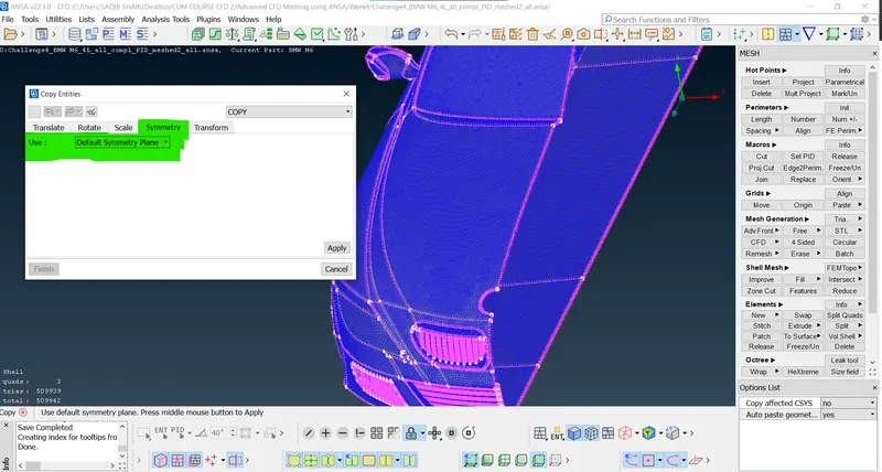
- After meshing all the PID's now mirror using the copy command from the tool box:
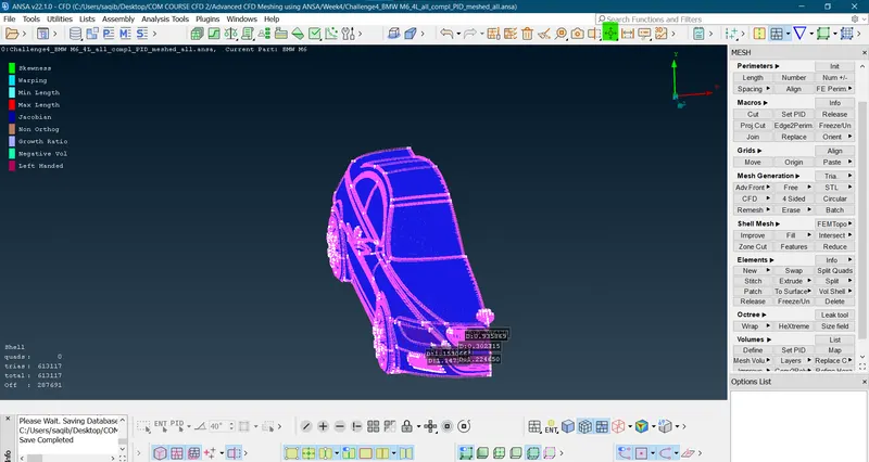
- Now Mirroring is done for the symmetric part:
- First the copy entity option is seclected(hide the logo), select the entity option > select the entities > middle mouse:
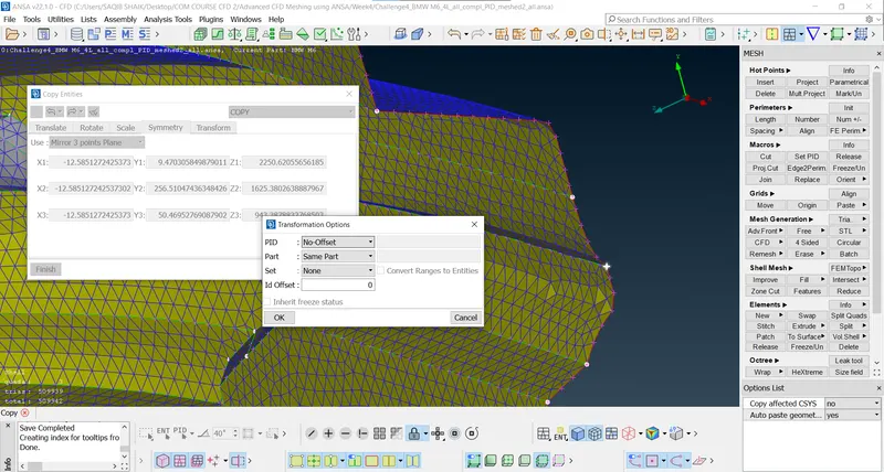
- Then three points on the symmetry line are selected so to capture all the major curves:
- Select three points and with no offset copy the symmetic part of the geometry:
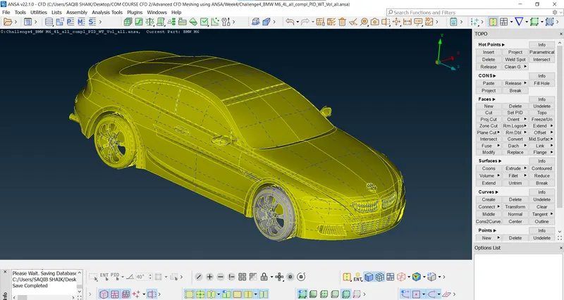
- Now as the geometry is copied topo can be done too fix the single coon issue:
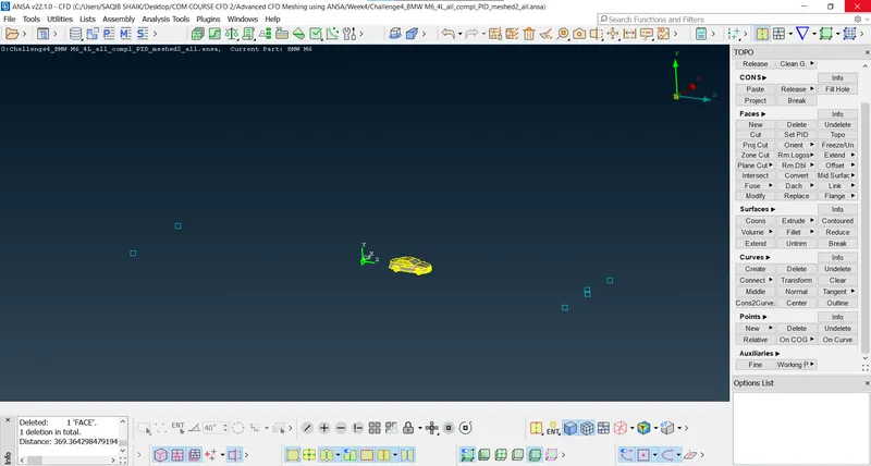
- Now creating the wind tunnel volume:
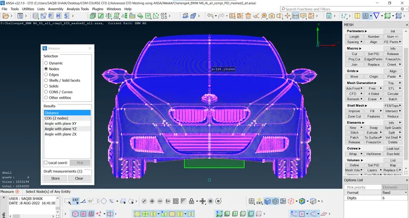
- Measure the geometry length: Approx - 1305 mm.
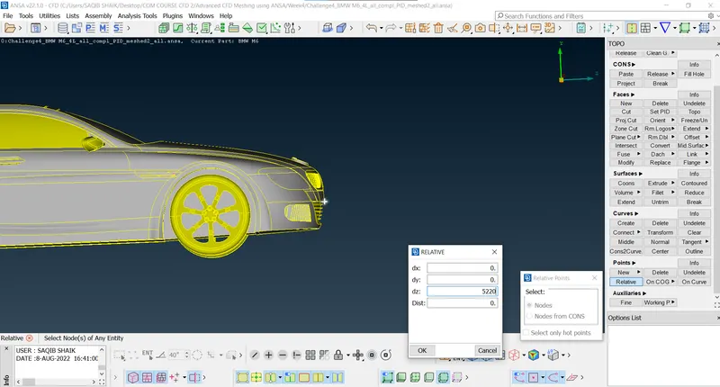
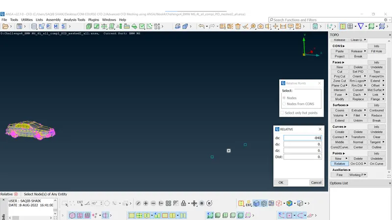
- Create the point with relative option:
- Front 4 * 1305 = 5220mm.
- Back: 6 * 1305 = 7830mm.
- Top: 3 *1305 = 3915mm.
- Clearance(Down from first relative point) = 113 ~ 115mm Approx.
- Sides: From center - 1305mm
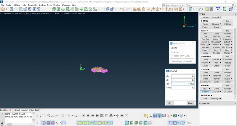
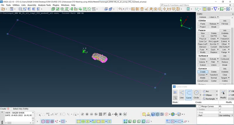
- Creating the surface:
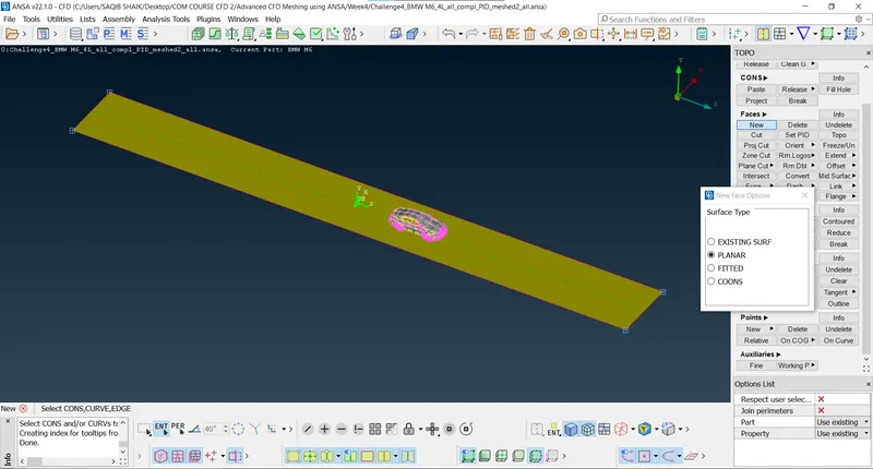
- The below surface is kept with some distance from the tyres to avoid any sharp edge penetration/intersection errors.
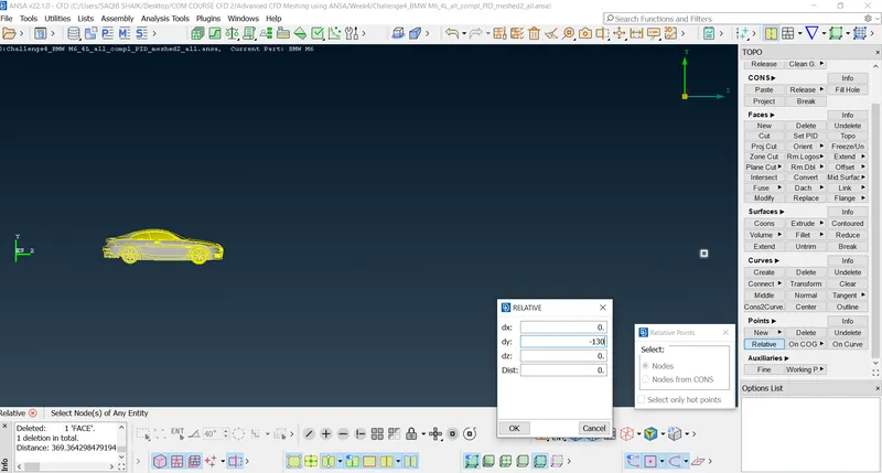
- 1305 in negative and positive x-direction for the sides.
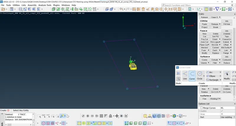
- Creating the curves to create surface:
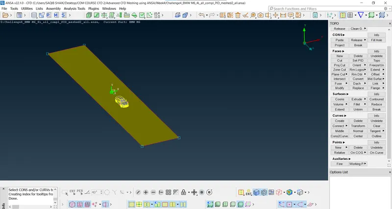
- Using the new surface command:
- The height from the base plane to the top of the car is ~ 375 mm, so for the top surface 375 + (3*1305) = 4290 mm.
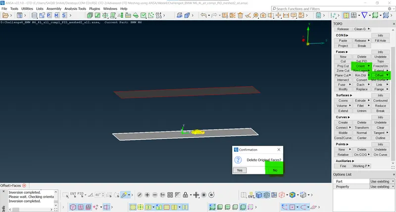
- Now creating the other surfaces:
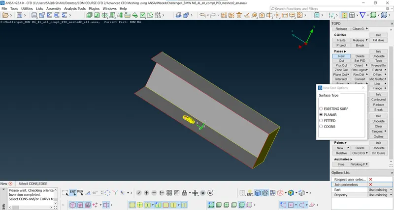
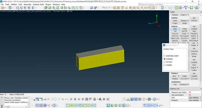
- The wind tunnel is named in PID's:
- Meshing the Wind Tunnel:
- As we are interested in the volume around the car we will have finer mesh near the car and coarser as we move away from the surface:
- For the top surface defining the length as 100m:
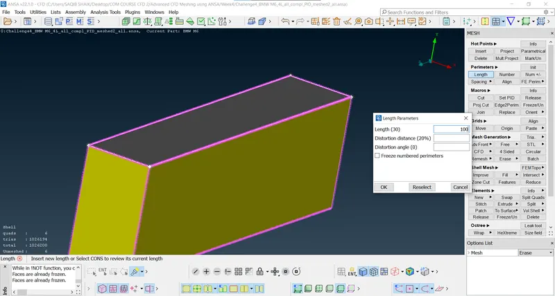
- Macros:100mm:
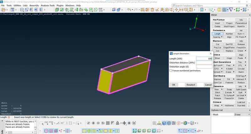
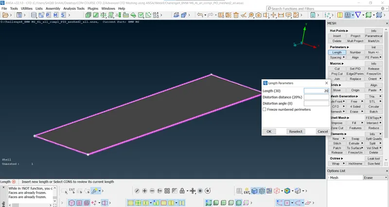
- For the base surface Perimeters and Macros: 20mm.
- Now the vertical edges are given the variable bias of 1.1 and the start is 20 mm and limit is 100 mm.
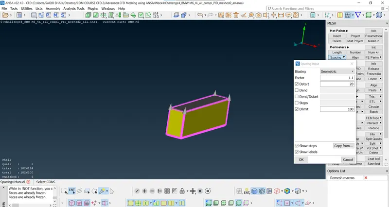
- It can be seen that the length of the elements is varying from 20mm to ~100mm:
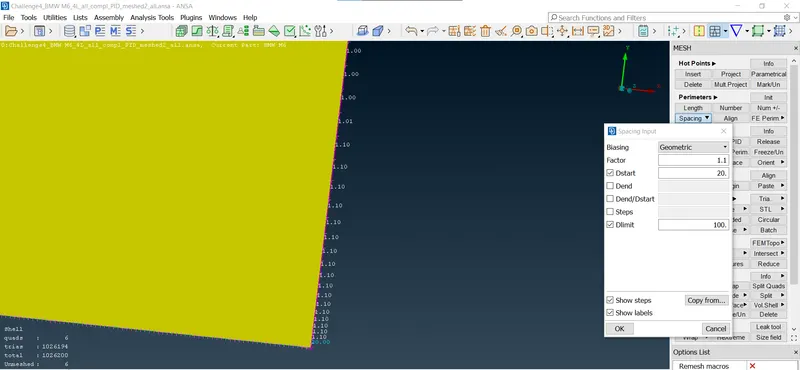
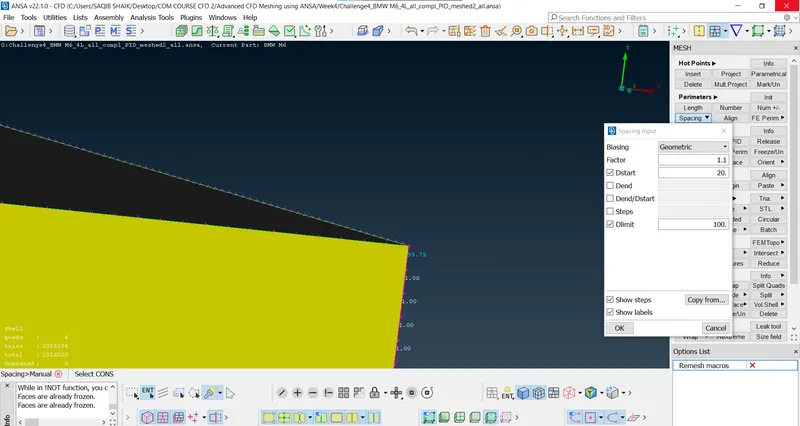
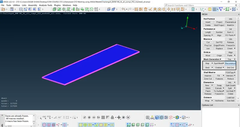
- Base surface(min-15mm):
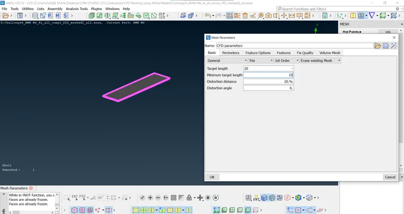
- Using the spot mesh for the visible part:
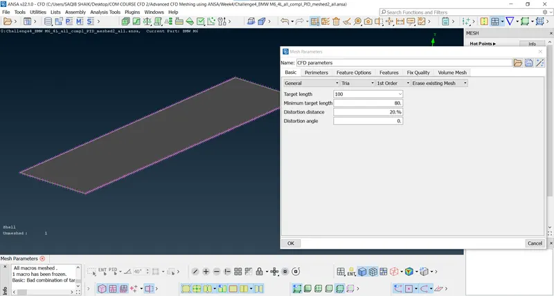
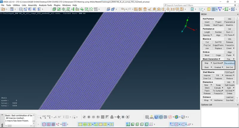
- Topsurface Windtunnel(100 mm):
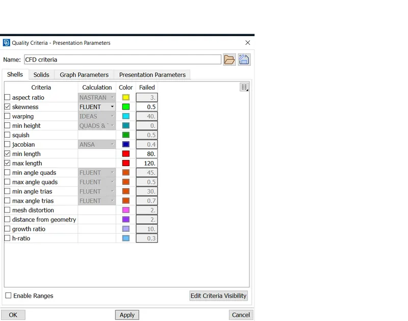
- Min - 80mm:
- Front, Rear and side surfaces(spot mesh > select):
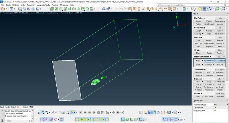
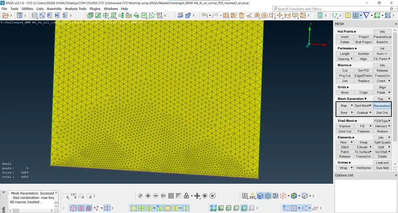
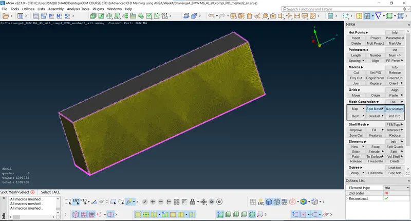
- Surface Meshing of the wind tunnel is completed.
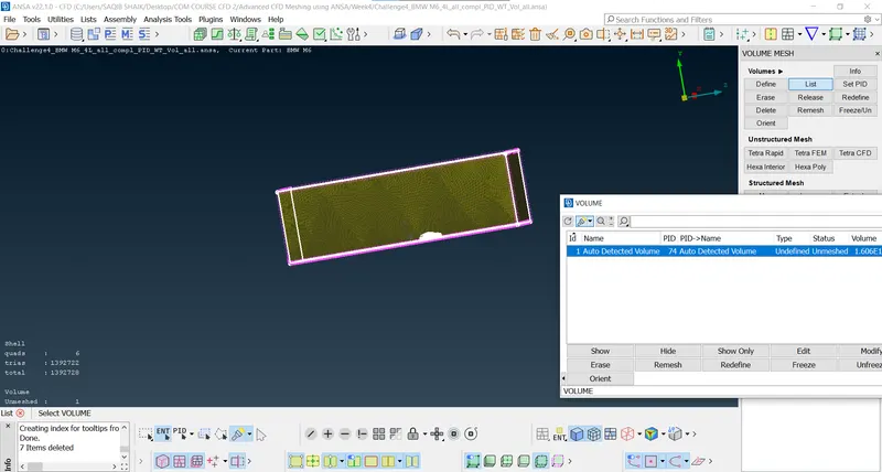
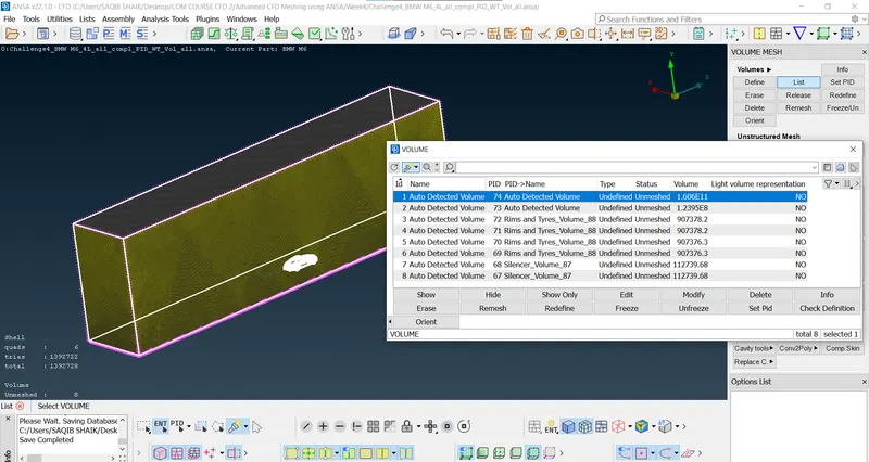
- Now check the volumes:
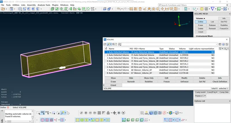
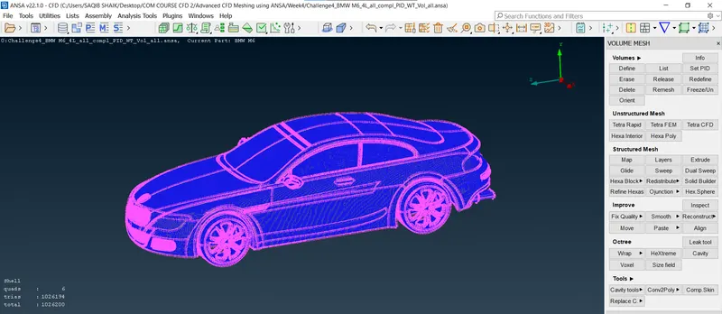
- The hightlighted volume shows the volume of the wind tunnel used for the aerodynamic analysis.
- Next step will be to mesh the volume of th windtunnel after deleting the other volumes:
- Tetra Rapid:
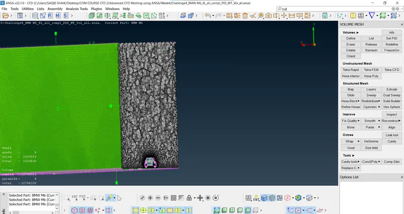
- Tetra CFD:
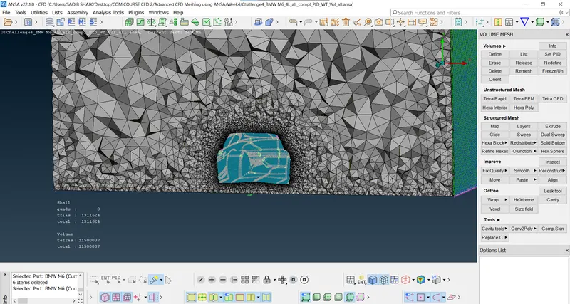
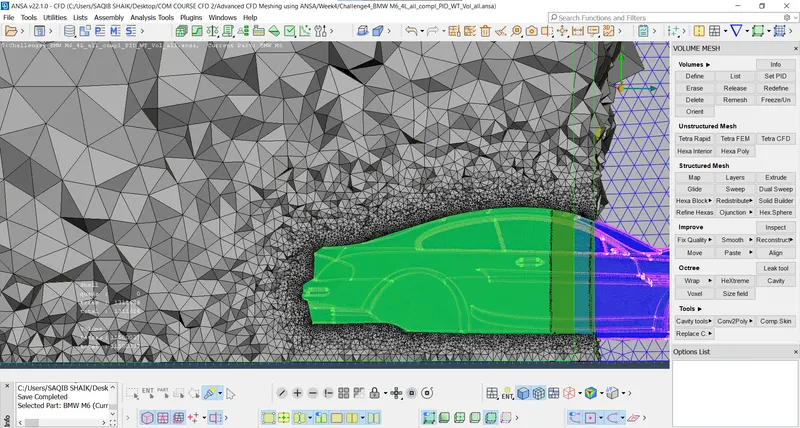
Results and Conclusions:
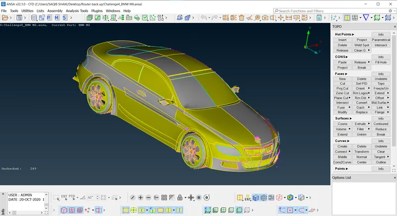
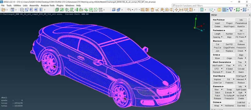
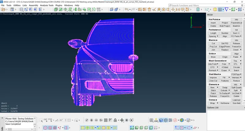
- The geometry is cleaned and meshed successfully as for the given target length and quality criteria (clearing all the errors):
- Before:
- After:
- Before:
- THe geometry is successfully mirrored(copied):
- Before:
- After:
- Before:
- Creating the windtunnel:
- Before:
- After:
- Before:
Learning Outcomes:
- Clear the geometry of the errors.
- Using the CFD mesh with different properties and criterias.
- Defing the fail criteria.
- Importance of growth rate.
- Defining the finer mesh for the regions with intreset and comparetively coarser to the others.
- Considerations made for the aerodynamic analysis.
Geometry Links:
Volumetric Geometry Links:
- https://drive.google.com/file/d/1K232sJo0LJn3foSRs00sJrgalJMaA3YB/view?usp=sharing
- https://drive.google.com/file/d/1PfL61zAFQB3G99F2UFIdNHF_qEABlC4w/view?usp=sharing
Conclusions:
- The geometry is cleaned successfully and meshed in accordance with defined quiality criteria and dimensions.
- The Wind Tunnel is created using the dimensions mentioned and its meshed so as to focus near the car region(Fine mesh near the car/base surface of the windtunnel).
- The geometrical parts are defined in the PID.
- Checks are performed for the geometry to find any errors present and fixed.
- The process and the results comparing to the raw geometry are mentioned in detail with the relevent figures.