Week 4 Challenge : CFD Meshing for BMW car
AIM `to`
For the given model, check and solve all geometrical errors on half portion and Assign appropriate PIDs. Perform the surface meshing with the given Target length and element Quality criteria. After meshing the half model, Do symmetry to the other side.
- Target lengths for the different parts of a model are as follow:
- Body - 3 mm
- Lights - 4 mm
- Grills - 1 mm
- Rims and Tyres - 2 mm
- Optical Rear view mirror - 2 mm
- Window - 2 mm
- Silencer - 3 mm
- Logo - 1 mm
Geometry `to`
|
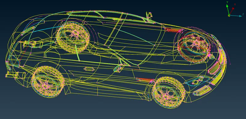
wireframe view
|
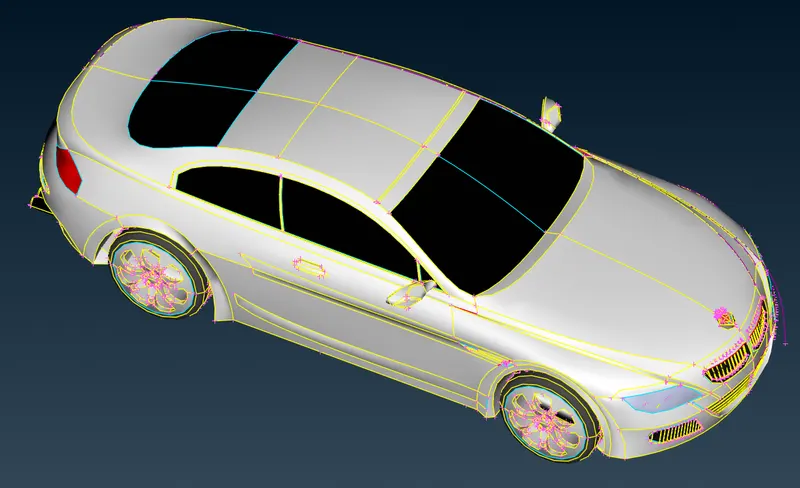
PID view
|
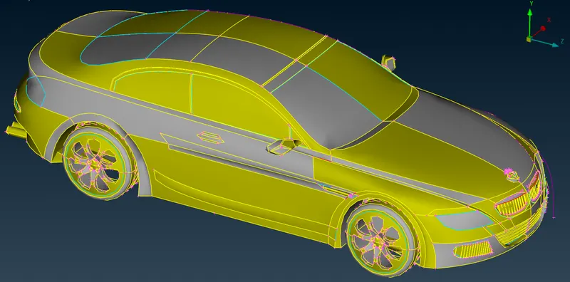
Entity View
|
PROCEDURE `to`
- The geometry had too many single CONS . The first step is to apply the Faces >Topo, which gives the model as shown in wire frame above.
- The PID view as shown above is not able to capture the car's features accurately. The resolution for the car deatures were very large. So, in that case, changin the distance between two nodes in the mesh topo can increase the the car's features. Hence, the resolution was increased by selecting MESH TOPO > PERIMETERS > LENGTH > PERIMETERS LENGTH = MACROS LENGTH = 1MM. The difference is as shown below.
|
Before increasing the resolution
|
After increasing the resolution |
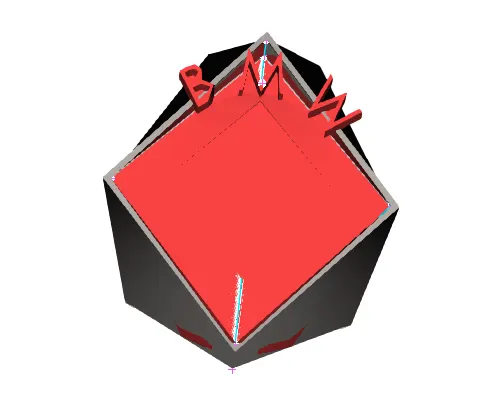
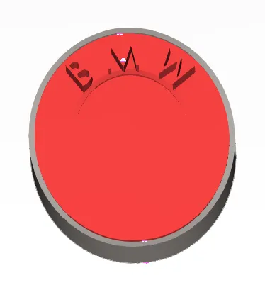
- Here the car model is symmetric. So it is better to do geometric cleaning, meshing in one half of the car. This done by deleting one half of the car that excludes the logo.
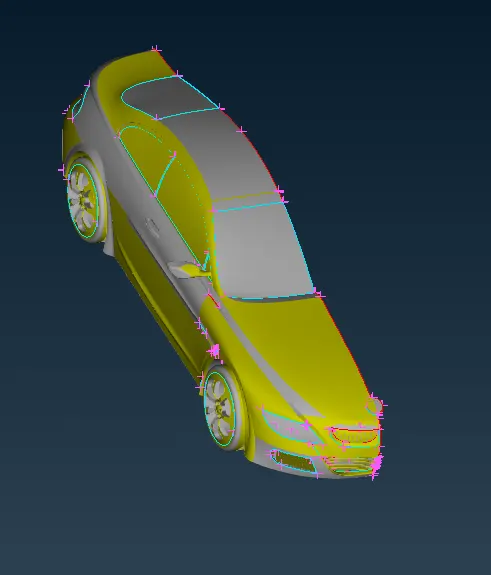
GEOMETRY CLEANING
- The car now has 3 front grills, 1 headlight, 4 windows, 2 tyres and rims, 1 mirror, 1 silencer and the remaining as the body of the car. These metioned can be represented as the overall PID's of the BMW car. Now each PID is geometry cleaned, step by step for an aerodynamic wind tunnel simulation. For this purpose, the whole car should water tight. Each PID's were geometry cleaned for unwanted single and triple CONS. This will reduce the unnecessary meshing power and time.
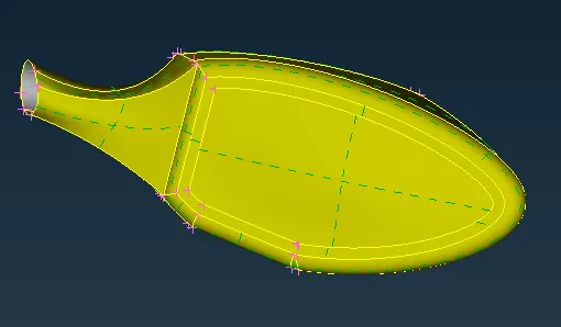
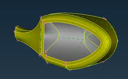
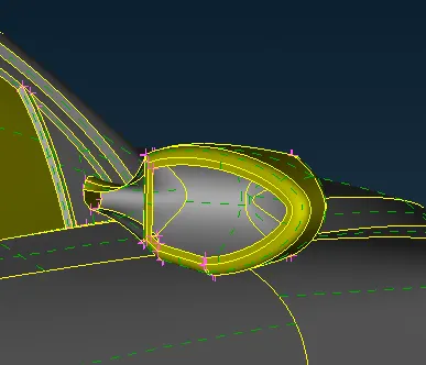
- First of all, the mirror is geometrically cleaned. The mirror is connected to the car body and has unwanted inner surfaces which are not required for a water tight geometry. So those surfaces are deleted. Also, the connection joining the
 |
 |
 |
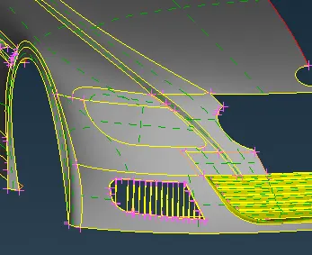
- Next is the headlight. The headlight had many inside surfaces which are not in contact with the outside surface. So its not needed. The below figure shows the before and after geometry cleaning of the headlight, respectively. The headlight is given only a new surface from outside using the comman FACES > NEW > COONS.
 |
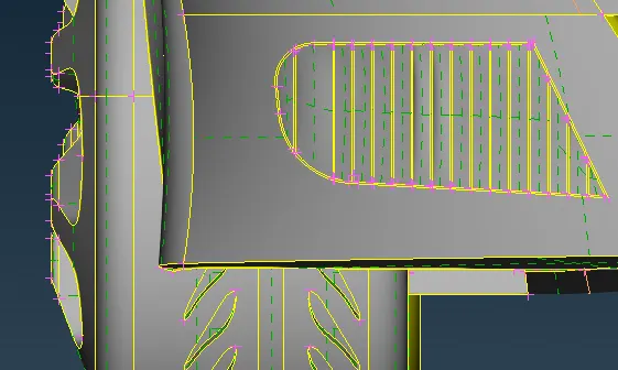
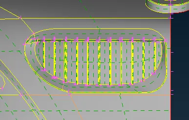
- Then the grills at the front are cleaned. There are 3 grills at the fron. Each grills have to be closed from inside. The difficulty arises in closing these open structures at the back of the grill from inside, as they are irregular in shape and have many overlapping and protruding surfaces. So many newly made CONS are made to bring a definite shape, using the command CURVES > CREATE > LINE, followed by FACES > NEW > COONS. Even after making new faces, there will be tripple CONS. These occur when the surfaces made are projecting or not coinciding with the adjacent surfaces. All these can be resolved by giving extra shaping to the alreading existing surfaces using the cutting command FACES > CUT, followed by FACES > NEW > COONS. The below shown figures are the before and after of each grills.
|
Before |
Before | Before |
|
After
|
After
|
After
|
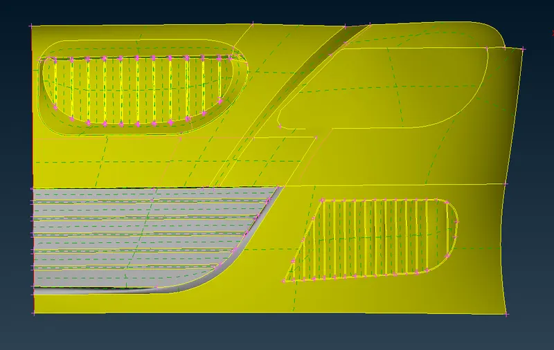
- Next is the floor of the car. There were many ups and downs on the floor of the car which are unnecessary geomertical features. Its better to make the floor flat instead of irregular surfaces. The surfaces with unwanted shapes have liitle effect from the simulation point of view. The figure below also shows te before and after the geometry cleaning.
|
Before |
After
|
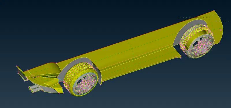
- Next is the rims and tyres. The tyres had overlapping surfaces from the car floor on to the tyres. This caused overlapping surfaces. This will lead to intersection errors while geometry checks.
| Before |
After
|
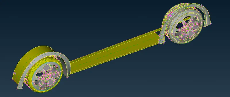
- Glasses didn't needed much of geometry cleaning. But they had beads inside the cars surface. These were not necessary because this geometry cleaning of BMW car is meant for wind tunnel simulation. So inside surfaces were the least important and also unwanted in terms of meshing.
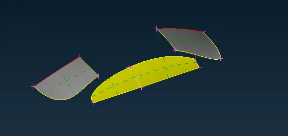
- The silencer PID had inside surfaces. So they also were deleted. The external features were needed, so nothing were deleted.
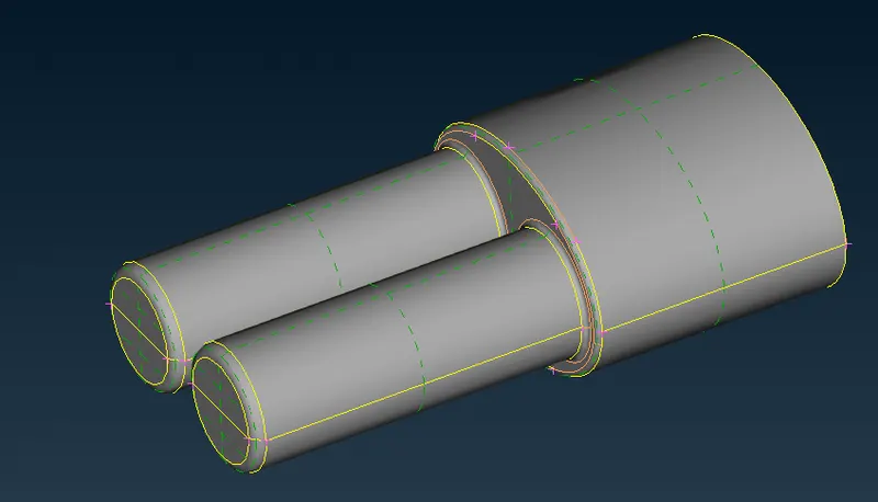
- After all the geometry cleaning, the car model is subjected to geometry checks. It is possible to have errors like single CON error and penetration errors. These errors must be rectified for successful volumetric meshing.The warnings can be ignored. Also some of the single and triple CONS can be neglected, as they aare unavoidable.
SURFACE MESHING
For surface meshing, each PID is given separate mesh size. This is because, each PID has different geometry and for covering the whole surface of PID with proper mesh, there should be optimised mesh size. The mesh generation adopted is CFD type. The mesh size adopted for each PID is mentioned below -
- Body - 3 mm
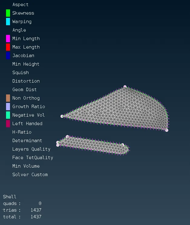
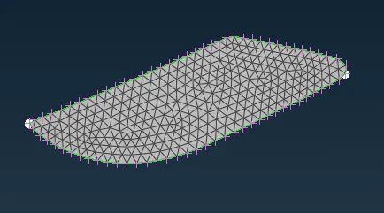
- Lights - 4 mm
- Grills - 1 mm
- Rims and Tyres - 2 mm
- Optical Rear view mirror - 2 mm
- Window - 2 mm
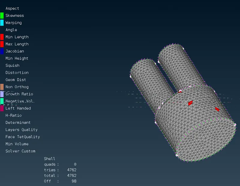
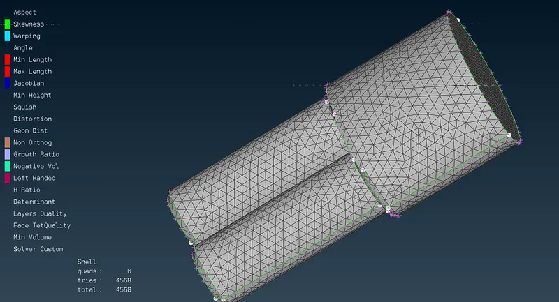
- Silencer - 3 mm
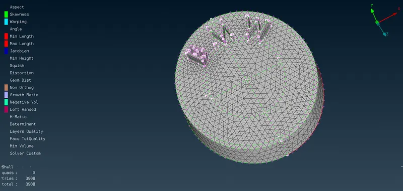
- Logo - 1 mm
For CFD meshing, there are 4 parameters to take note of - minimum and maximum target length, mininmum and maximum length, followed by the skewness factor. These are accurately mentioned for each PID. They are adopted as per the mesh size and are shown blow -
| PID | Mesh size | Maximum Target Length | Minimum Target Length | Maximum Length | Mimimum Length | Skewness |
| Body | 3 mm | 3.5 mm | 2.5 mm | 4 mm | 2 mm | 0.7 |
| Lights | 4 mm | 4.5 mm | 3.5 mm | 5 mm | 3 mm | 0.6 |
| Grills | 1 mm | 1.5 mm | 0.5 mm | 2 mm | 0.1 mm | 0.7 |
| Rims and Tyres | 2 mm | 2.5 mm | 1.5 mm | 3 mm | 1mm | 07 |
| Optical Rear View Mirror | 2 mm | 2.5 mm | 1.5 mm | 3 mm | 1 mm | 0.7 |
| Window | 2 mm | 2.5 mm | 1.5 mm | 3 mm | 1 mm | 0.7 |
| Silencer | 3 mm | 3.5 mm | 2.5 mm | 4 mm | 2 mm | 0.7 |
| Logo | 1 mm | 1.5 mm | 0.5 mm | 2 mm | 0.1 mm | 0.7 |
Note - After obtaining the initial mesh, there are chances that some mesh elements do not match the required specifications. These elements are known as OFF elements. It is necessary to nullify the OFF elements as far as possible. There are certain options under SHELL MESH to remove this OFF elements. (i.e. reconstruct, smoothing, reshape or changing the CFD mesh parameters)
- Recontsruct `to` When this flag is activated, meshing algorithms take into account the reconstruction parameters (defined in the Meshing Parameters window) so as to produce a high quality surface mesh.
- Smooth `to` This function automatically applies Smoothing attributes so as to 'relax' the mesh on already meshed Macro Areas or on FE-model shell mesh. The function may be applied to selected meshed Macro areas (Geometry) and/or FE-model shell mesh according to the chosen sub-option.
- Reshape `to` The Shell Mesh>Reshape function is applied on either meshed Macro Areas or FE models to improve mesh quality. The function performs automatically a combination of the following actions: Joins Perimeters, Inserts or Deletes Hot Points, Reconstructs the mesh, Creates quad zones around holes based on predefined rules.
NOTE `to` After meshing each PID, the component must be freezed by selecting the option FREEZE/UNFREEZE from MESH deck. It can be done by right clicking and dragging.
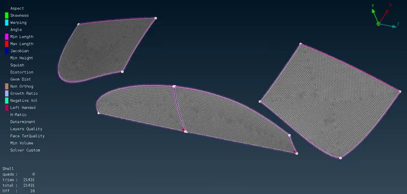
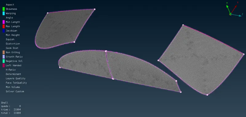
Below shown are some of the meshes adopted for the PID's `to`
|
Before Reconstruct
|
After reconstruct and reshape
|
- Lights `to`
  |
- Logo `to`
- Silencer `to`
|
Before reconstuct
|
After reconstruct, smooting, reshape and grid moving
|
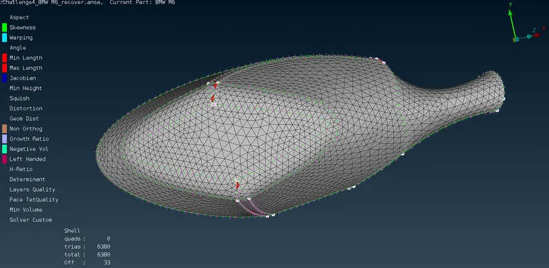
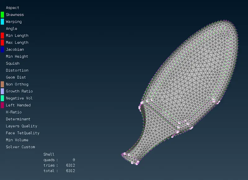
- Mirror `to`
|
Before reconstruct and reshape
|
After reconstruct and reshape
|
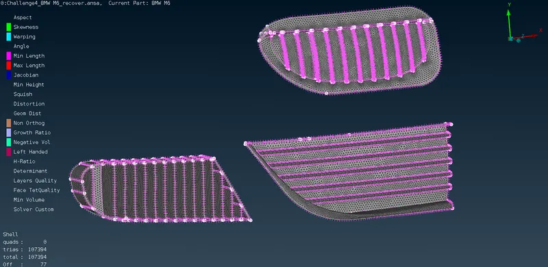
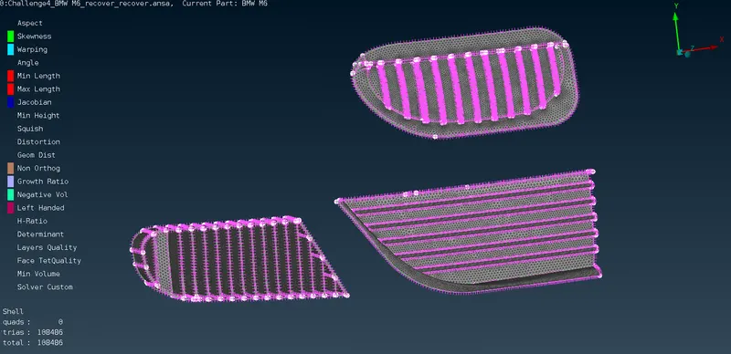
- Grills `to`
|
Before reconstruct
|
After Reconstruct
|
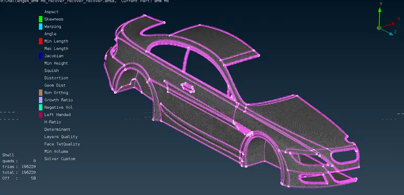
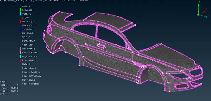
- Body `to` here CFD mesh was giving too much of OFF elements. And when the reconstruct, smoothing and reshape options where given, it was not giving the desired result of 0 OFF elements. Hence the SPOT meshing was adopted.
|
Before reconstruct - used SPOT MESHING with 3mm target length
|
After reconstruct and reshape - only 1 OFF element left
|
- Tyres `to`
|
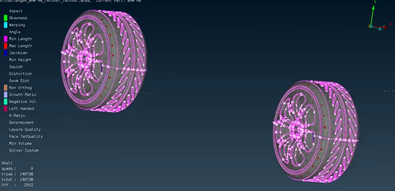
Before reconstruct
|
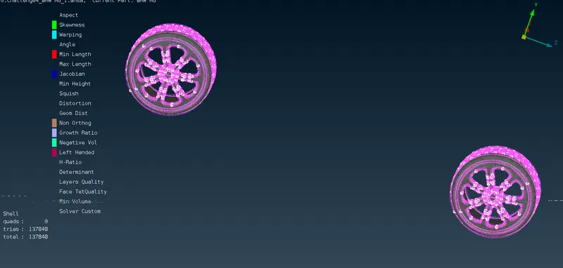
After reconstruct, reshape and improving the quality of the elements
|
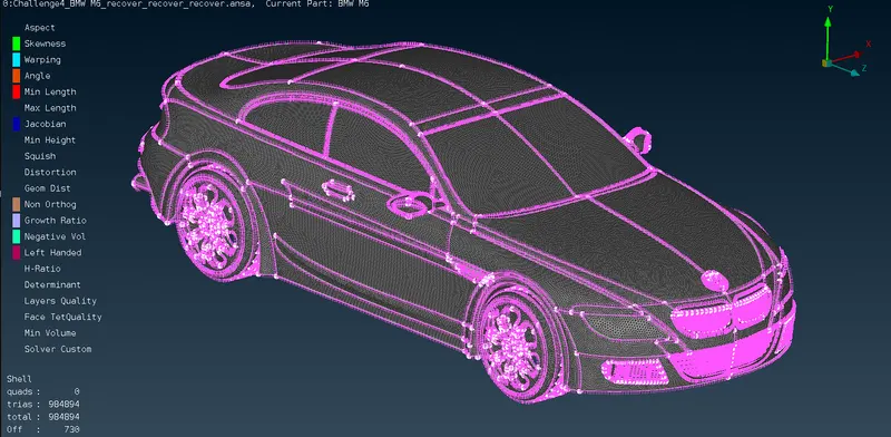
- Since all the PID's have been meshed with 0 OFF elements, one-half of the car is ready to copy to other side. By copying, we will get the same mesh elements as it was on the left-hand side. This can be done by COPY command in TRANSFORM option. The whole left-hand side car is selected for copying as the ENTITIES. It will ask for what type of symmetric procedure have to be adopted, choose Symmetry by 3 point plane. This way the whole BMW car will be obtained.
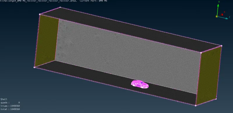
- Now, a wind tunnel that encloses the whole car is modeled. The wind tunnel dimensions are as shown in the figure. The value of X = 1305 mm. After that the wind tunnel is meshed using SPOT meshing with a mesh size of 80mm (tria). The wind tunnel is modeled by first creating points, such as using the command RELATIVE > NODES (in the TOPO deck). Then these points are joinded using CURVES command. A surface is modeled using FACES > NEW > PLANAR(in the TOPO deck). These commands where used to make the lower surface of the wind tunnel where the car is seated. To make the upper surafce of the wind tunnel, OFFSET command in the TOPO deck is used.

LEARNING OUTCOME `to`
Geometric Cleaning `to`
- The whole BMW car surface meshing was carried out with in-depth geometry cleaning for aerodynamic simulation purposes.
- When comes to wind tunnel testing, the model should water tight. This made the geometric cleaning hectic as the geometry had many irregular surfaces that are not required.
- The needle shaped surfaces are very likely to create geometry errors. This can be nullified by cutting those needle shaped surfaces and creating new surfaces.
- The single and triple CONS are most of the times converted to double CONS, but some are very much needed as per the geometry requirements.
- Sometimes the hotpoints do create error while geometry checking. Those were the hotpoints which are meant to be deleted. Similarly the CONS made by the user also needs to deleted after the surface creation.
- The penetration errors will necessarily occur if the surfaces overlapes. These overlapping surfaces can be seen as a glitch.
- The errors caused by not creating intersection between any two surfaces can lead to penetration errors.
- The errors caused by cracked surfaces in the geometry check can be resolved by automatic fixing.
Surface Meshing `to`
- The CFD meshing are likely to create OFF elements if the max and min length given are not appropriate.
- while meshing one part, other parts must be freezed or else, other surfaces will also get affected.
- For BODY PID, the CFD mesh gave large numbers of OFF elements. But when SPOT meshed, the OFF elements where nullified by using reconstruct and reshape.
- While using SMOOTH option, if the OFF elements are increasing , then do ctrl+z (undo).
- Grid movements comes in handy when the OFF elements are less in number.
CONCLUSION `to`
The BMW car is successfully geometry cleaned and surface meshed for wind tunnel testing. The wind tunnel enclosure was modelled around the car.
Google Drive `to`
https://drive.google.com/file/d/1TaI-zS3kLl_2GQTBVrA3dlpTlViYCvYi/view?usp=sharing