Week 4 Challenge : CFD Meshing for BMW car
Aim:
Examine and rectify all geometric errors in the provided model's half section, and assign suitable PIDs. Execute meshing with the specified target length and adhere to element quality criteria. Once the half model is meshed, apply symmetry to replicate the results on the other side.
Objective:
Target lengths for the different parts of a model are as follow:
Body - 3 mm
Lights - 4 mm
Grills - 1 mm
Rims and Tyres - 2 mm
Optical Rear view mirror - 2 mm
Window - 2 mm
Silencer - 3 mm
Logo - 1 mm
Model: BMW M6
• Begin
hfh
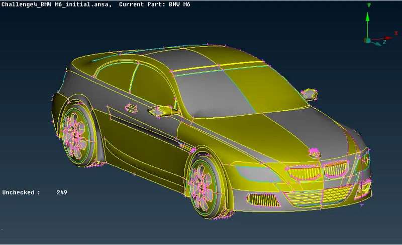
Procedure:
1. Topo/geometry clean-up:
• Begin by uploading the ANSA file onto the screen to facilitate topological cleaning and meshing in subsequent stages.
• Navigate to the mesh section and select the length option. Enter 1 mm for the parameters to refine the appearance of the car by smoothing out sharp curves.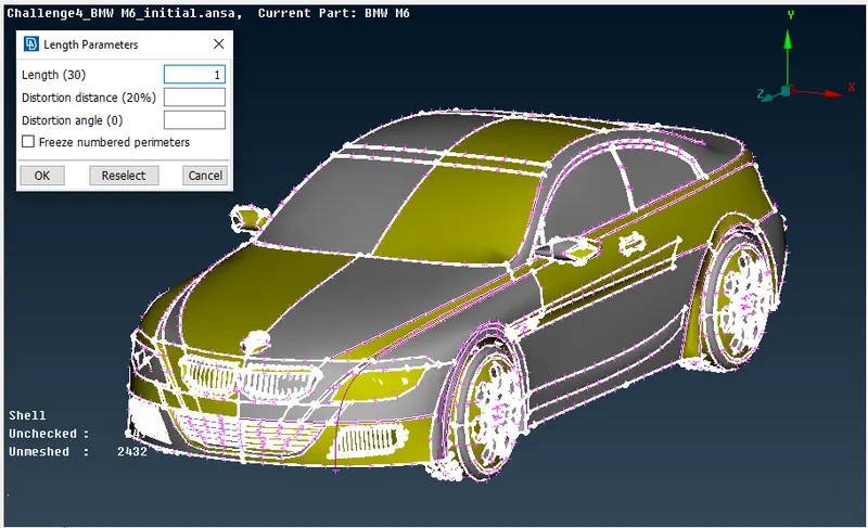
• As the car exhibits symmetry from the center to either end, delete one side of the car and carry out necessary operations. Utilize the symmetry option to generate the complete car based on the modified half.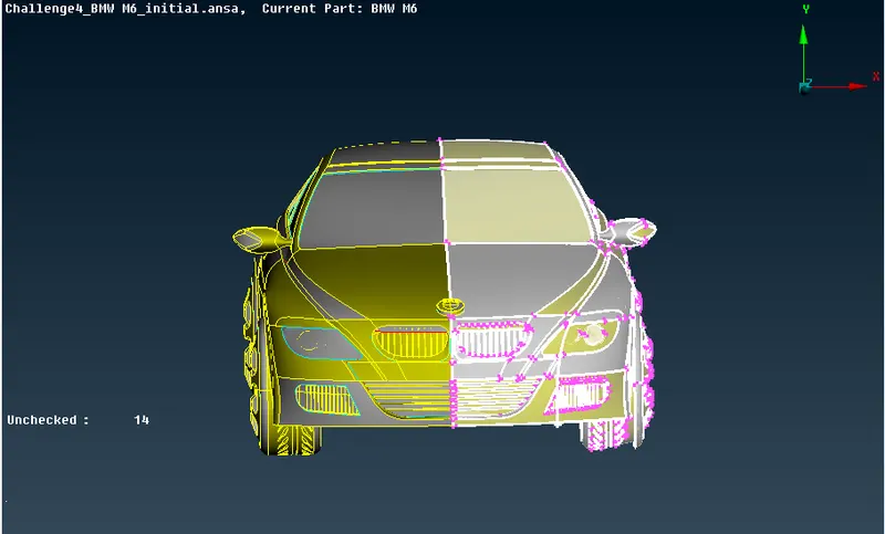
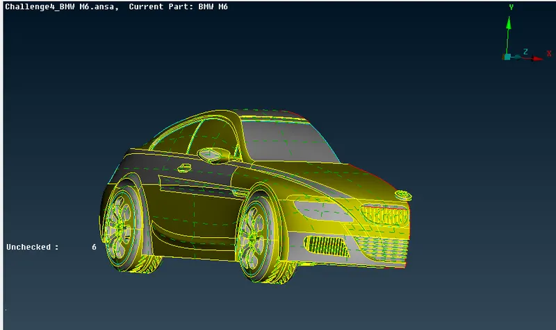
• Initiate the topological clean-up process by eliminating single and unnecessary triple connections. Click on "topo" and employ a box selection to identify and address any unjoined single or triple connections, facilitating targeted clean-up efforts.
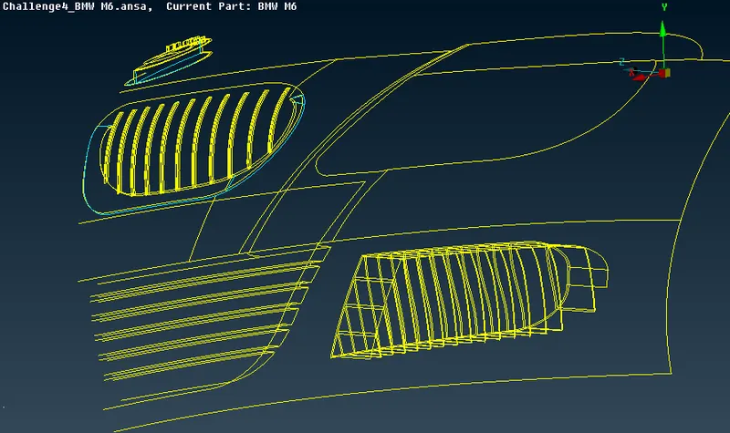
Front Grill Area:
- Start by focusing on the front grill area and headlights. Delete any surplus parts to ensure a unified volume throughout the car.
- Eliminate single and triple connections to maintain a single volume. Create double connections through strategic cuts and resurfacing, followed by removing unnecessary triple connections and surfaces using delete and other tools.
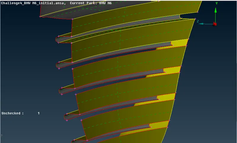
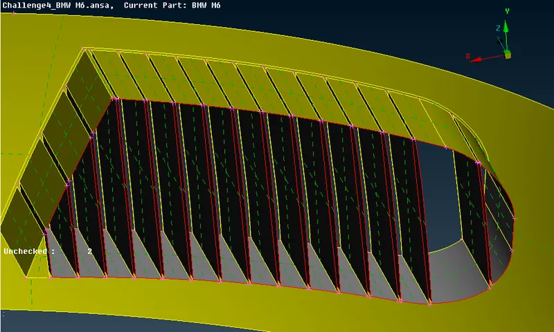
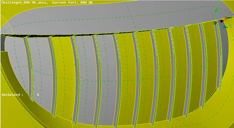
- Remesh and create surfaces to preserve a single volume.
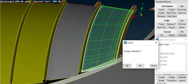
Windows, Rear Lights, Roof Region, and Logo:
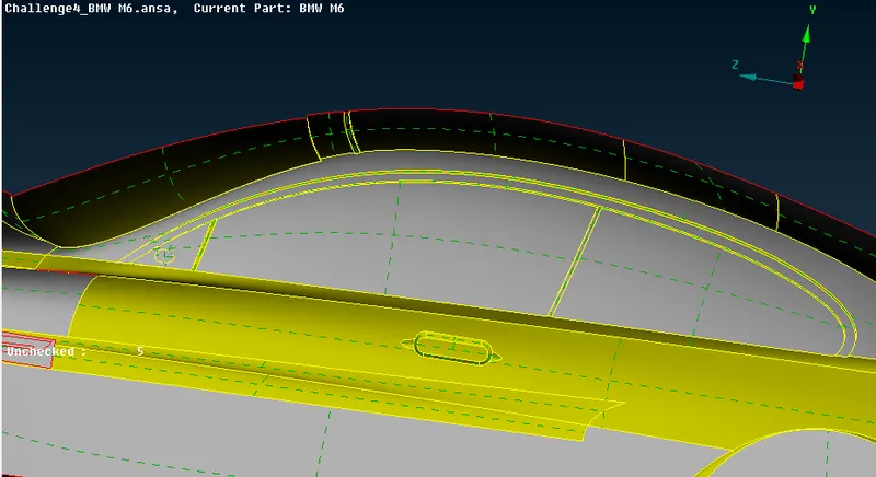
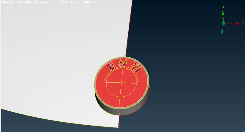
- Remove triple connections or extra surfaces in these areas, aiming for a single volume.
- Apply similar steps for windows, rear lights, and the roof, discarding redundant internal parts.
- For the car logo, use project cons to create a separate surface and delete extra surfaces to maintain a single volume.
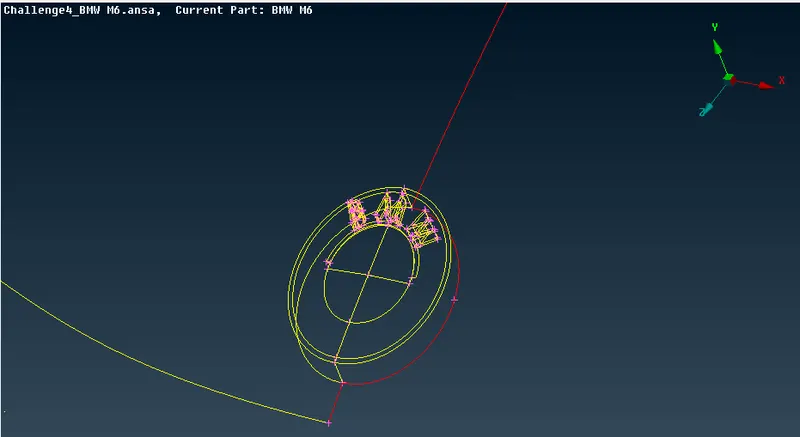
Design Feature and Mirror:
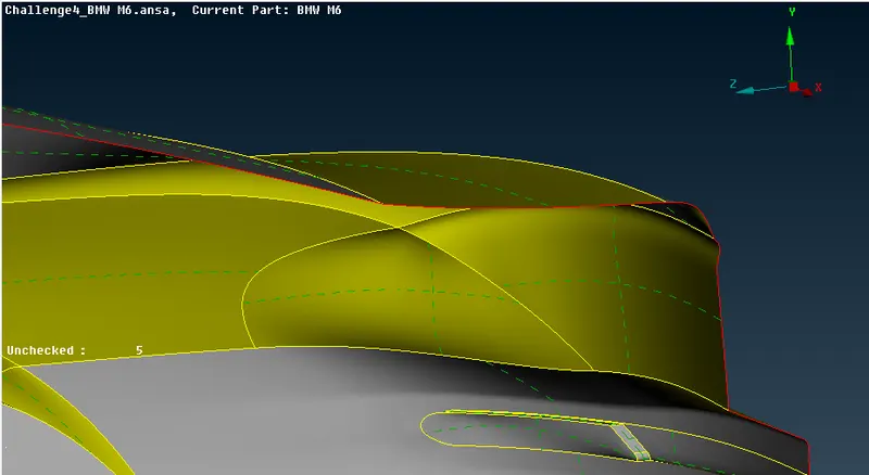
- Identify and delete unwanted single and triple connections, maintaining a common volume.
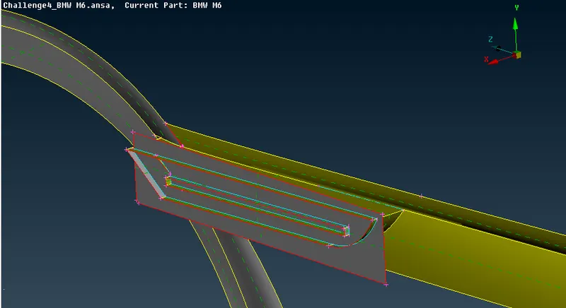
- Utilize the intersect option to identify and delete unnecessary surfaces at intersection areas.
- Extend single connections on adjacent surfaces to create triple connections and eliminate unwanted surfaces.
- Delete and recreate surfaces for a smooth shape at tight corners. Uncut necessary lines that might cause issues during meshing.
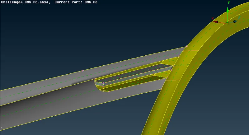
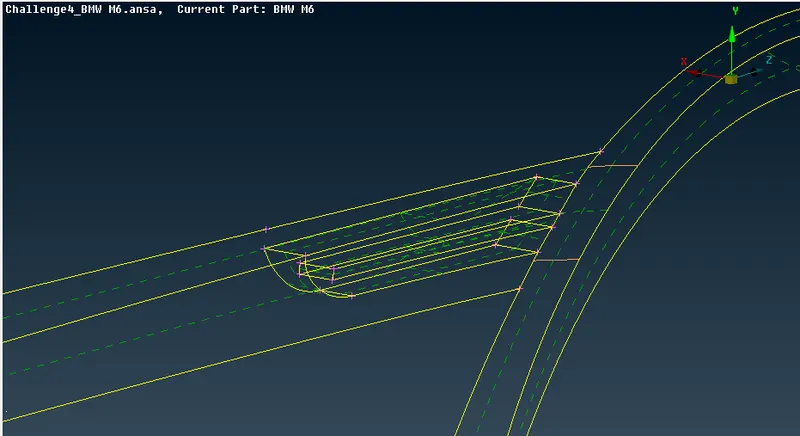
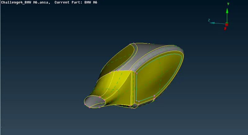
- Isolate the mirror, perform topological cleanup, hide obstructive surfaces, and create a single volume by deleting extras at the car-mirror connection region.
Wheel and Base Region:
- Isolate the wheels for geometry cleanup, rectifying triple connections, hiding obstructive surfaces, and deleting overlapping surfaces causing issues.
- Create larger surfaces after removing smaller parallel ones.
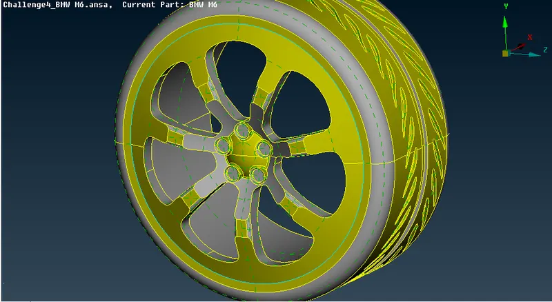
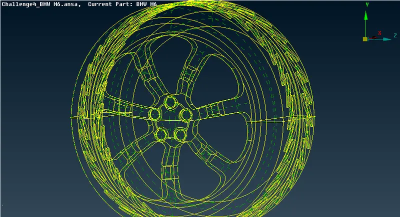
- Address the base of the car intersecting with the tire by deleting excess surfaces and unnecessary design elements causing smaller edges.
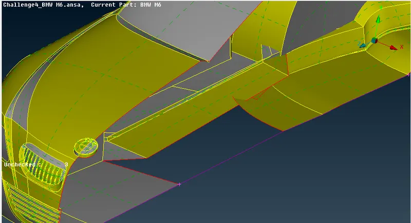
- Clean the entire base, ensuring smooth edges. Check for intersections with the tire region.
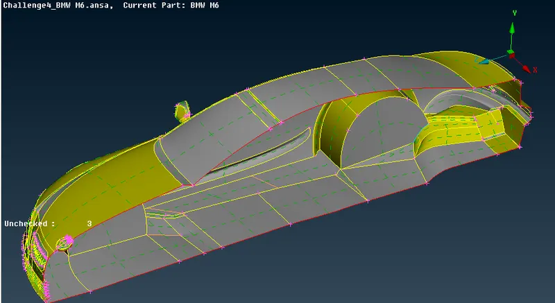
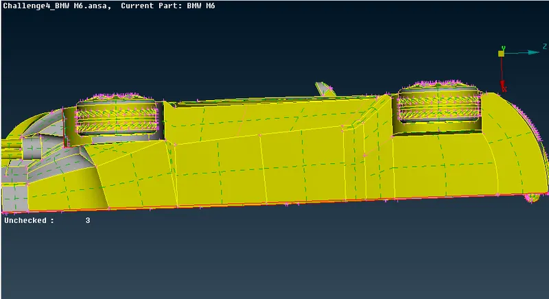
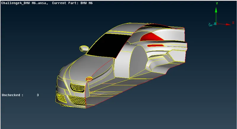
- After topological cleanup for the entire half car model, conduct geometry checks to identify cracks, unchecked faces, or other issues. Rectify as needed.
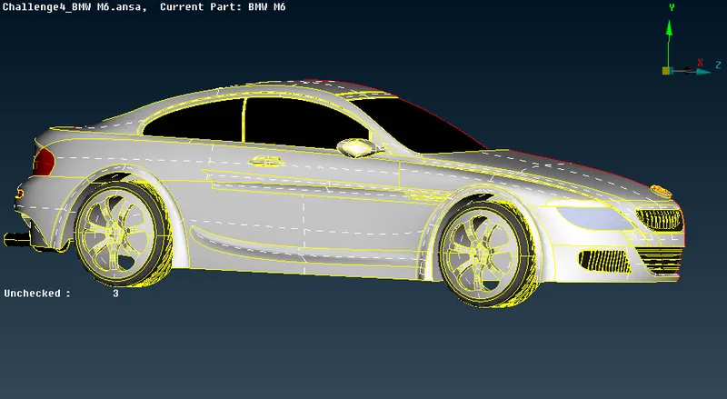
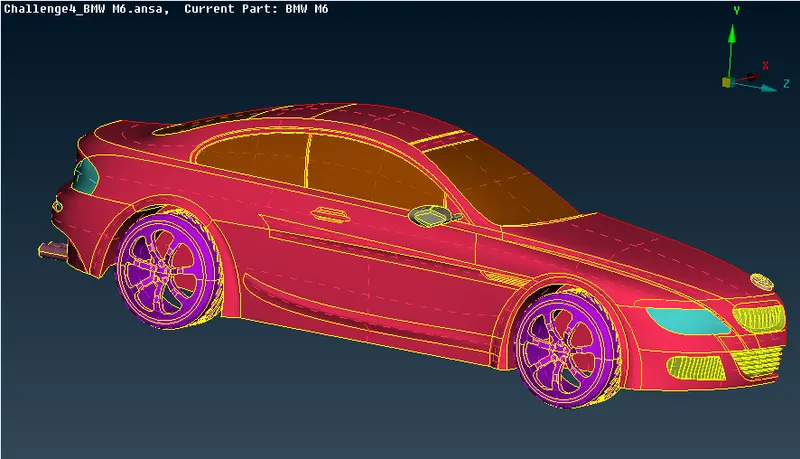
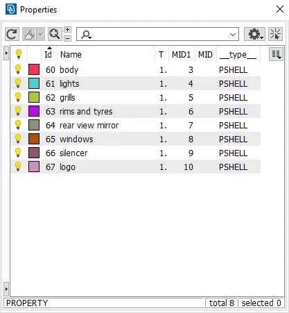
- Assign names to different components using PID after ensuring a clean geometry.
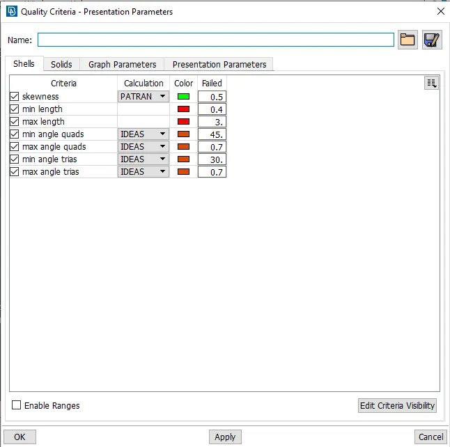
- Choose the quality criteria method for the openFOAM solver next to volumetric mesh. Select specified quality criteria.
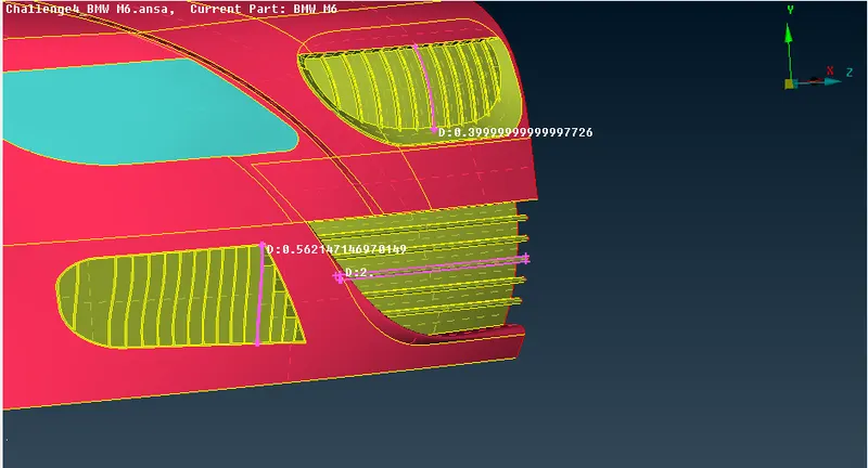
- Use the measure tool to calculate the smallest distance between connections or hot points.
- Adjust mesh parameters based on these measurements to prevent mesh failures.
2. Surface meshing:
- We must individually mesh the components as the specified mesh targets vary for each PID region.
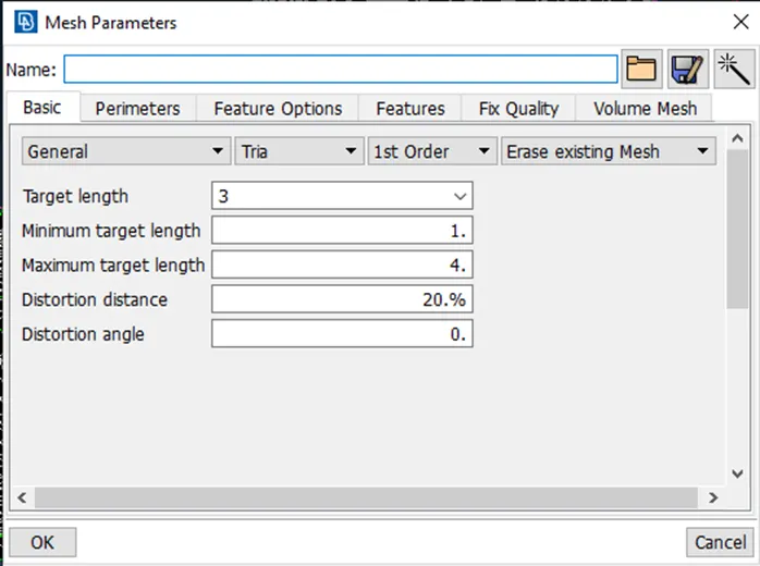
- Allocate the mesh parameters and quality criteria to each PID accordingly; ensuring the correct minimum and maximum lengths are assigned will mitigate mesh failures and off elements.
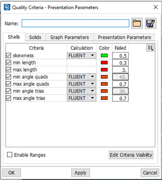
- Quality criteria for logo and grills region is given in blow image
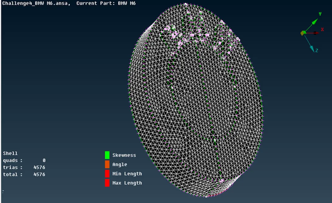
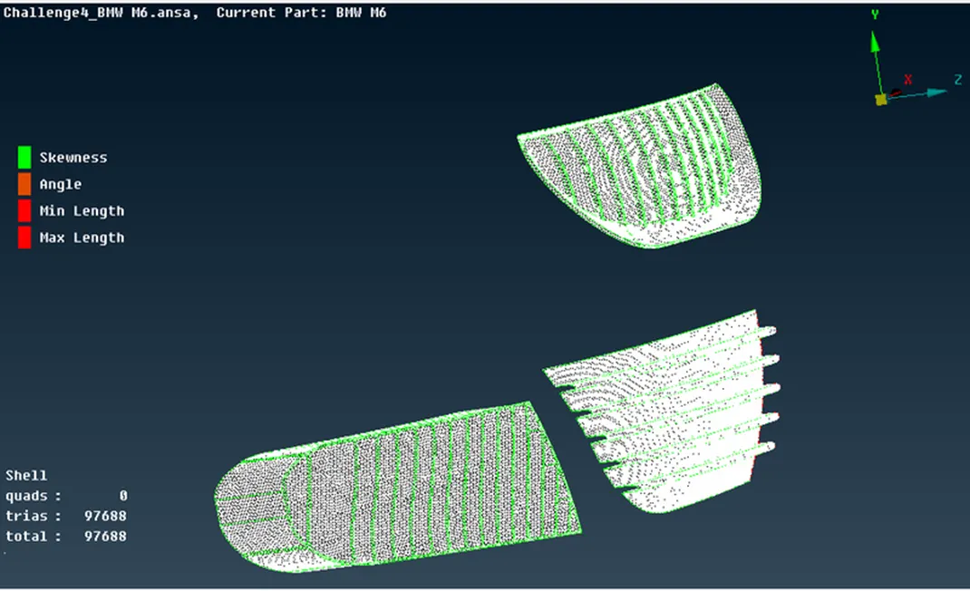
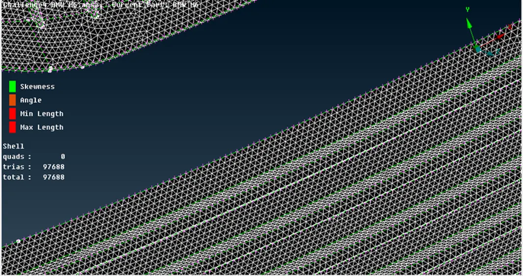
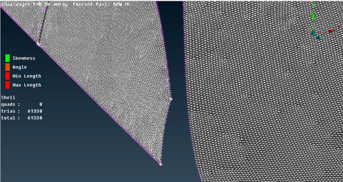
- Surface mesh for Logo and grill is given below
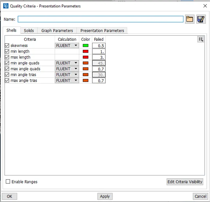
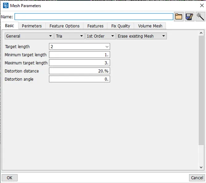
- Quality criteria for Rims and tyres, window and rear view mirror region is given in blow image
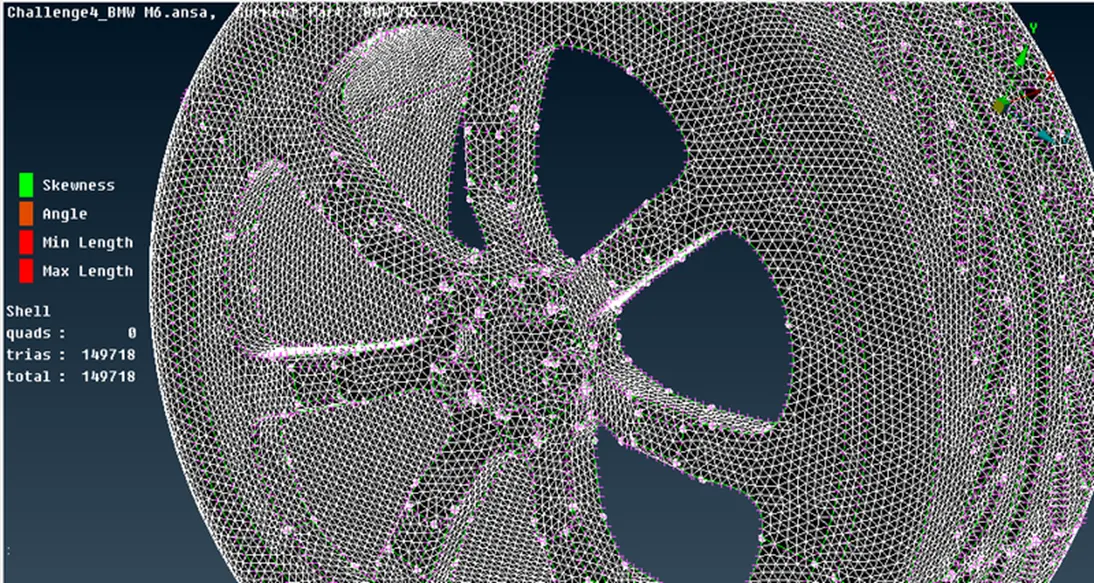
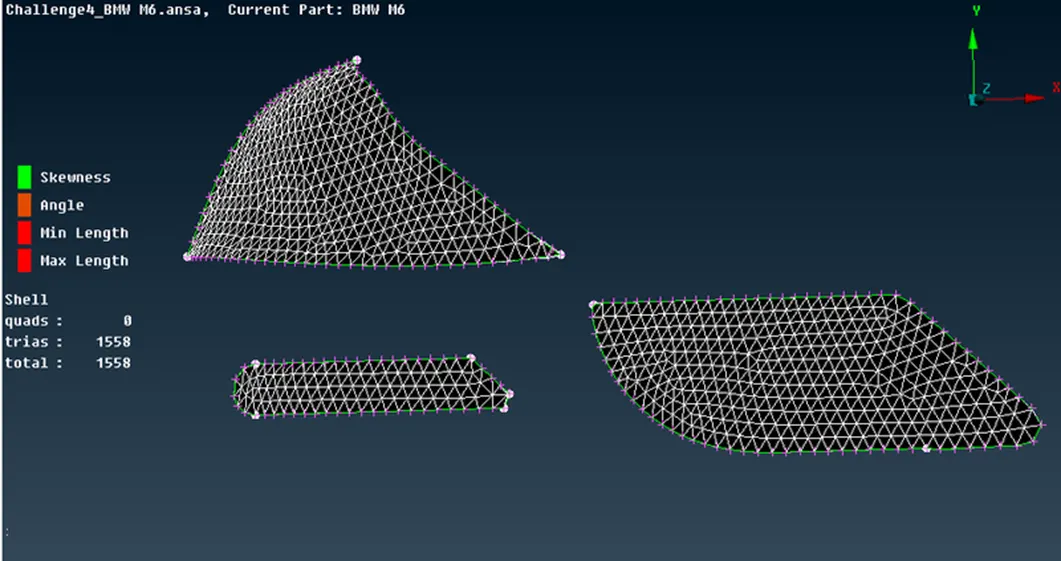
- Surface mesh for Rims and tyres, window and rear view mirror region is given in blow image
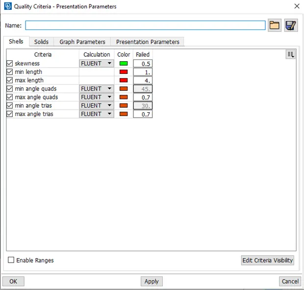
- Quality criteria for Silencer and lights region is given in blow image
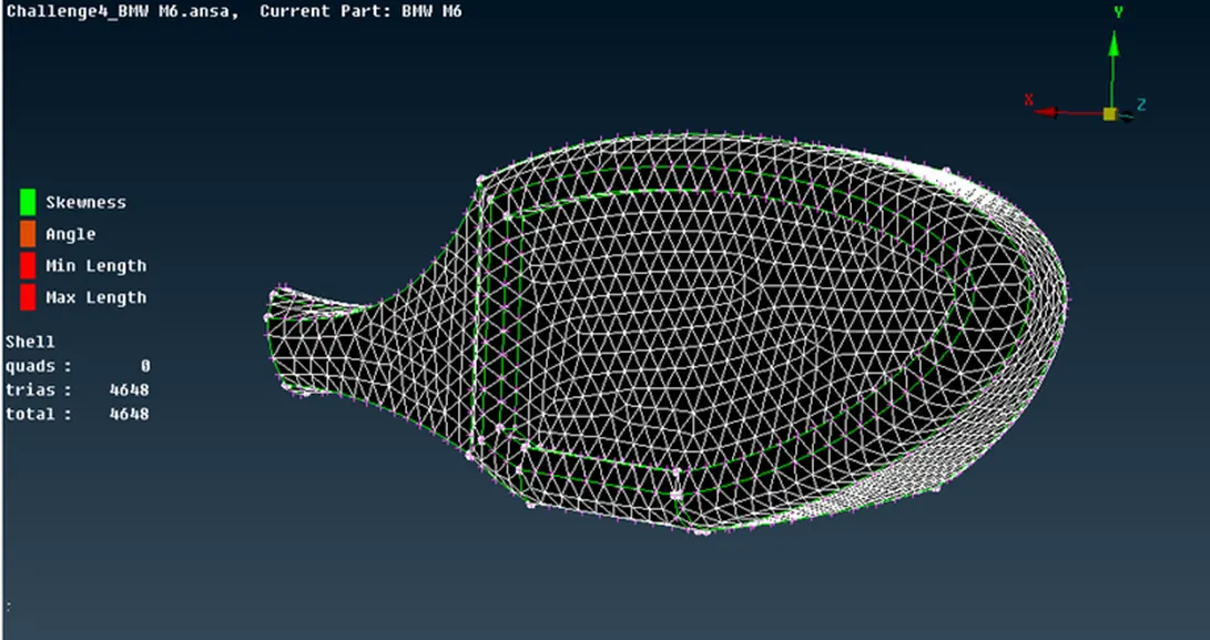
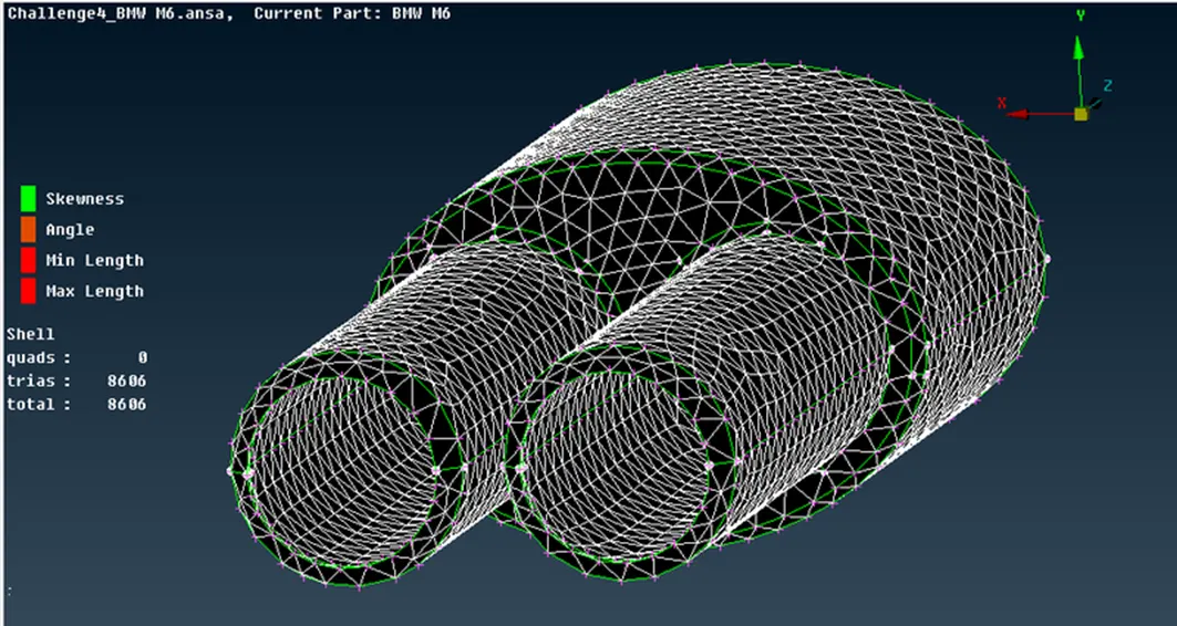
- Surface mesh for Silencer and lights region is given in blow images
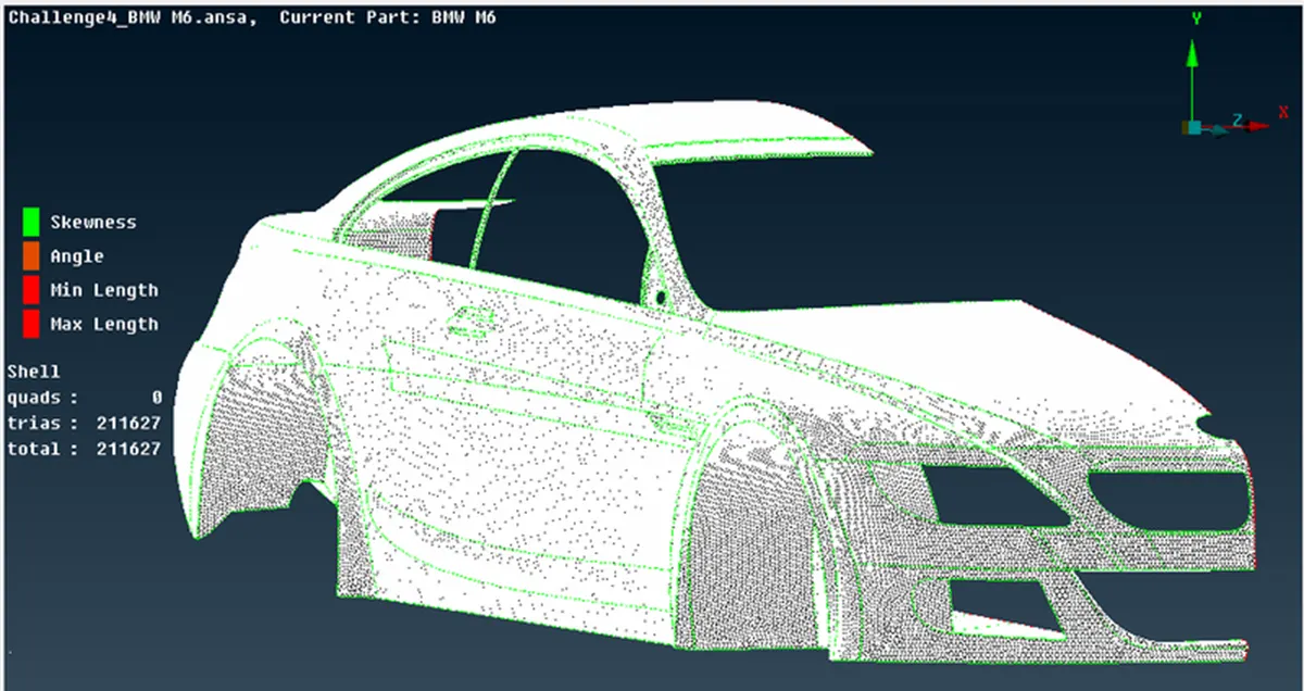
- Car body surface mesh
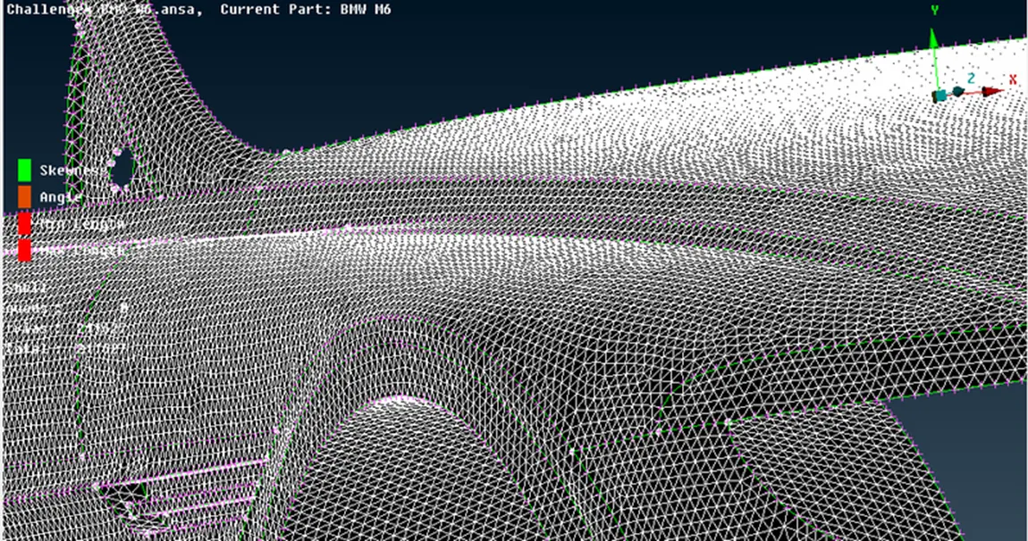
- As the body PID region interfaces with various other PIDs, variations in mesh length at the boundary of two different PIDs can lead to mesh erasure or failure. Consequently, when inputting lengths in the mesh dropdown, prioritize regions that do not interact with other meshed PID regions. This approach prevents mesh erasure, allowing for later editing to remove any off elements.
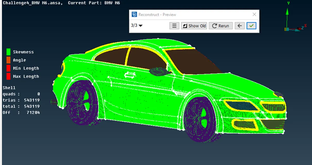
- After meshing, we can choose re-construct under shell mesh to reduce the off elements. And later the remaining off elements can be edited manually.
- Final surface mesh of car model is given below
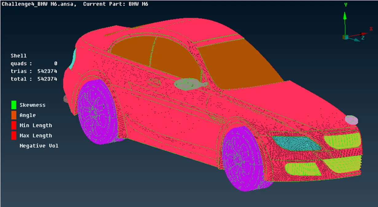
Performing symmetry on the car model
- Employ the symmetry option under the transform menu to generate an exact opposite body of the car, thereby creating a full-body car.
- Utilize the copy option, selecting the half-body car while excluding the logo since a duplicate of the logo is unnecessary.
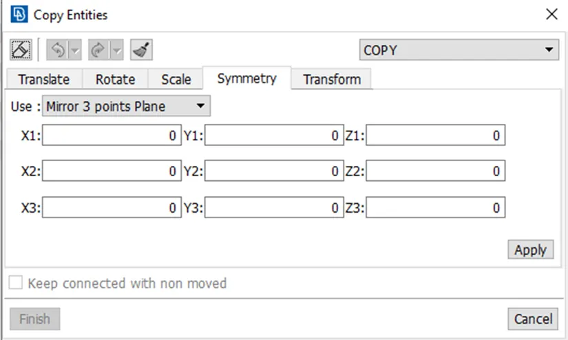
- Upon selecting the model, execute a middle click on the mouse to open a window. Opt for symmetry, then choose 'mirror 3 points plane' and designate three points along the edge for the symmetry operation.
- After selecting the three points, double middle click to execute the symmetry. Confirm the geometry by middle clicking again, finalizing the process.
- Address any isolated inconsistencies near the middle section by using paste or other relevant tools to resolve the issue.
- Symmetry conditions window
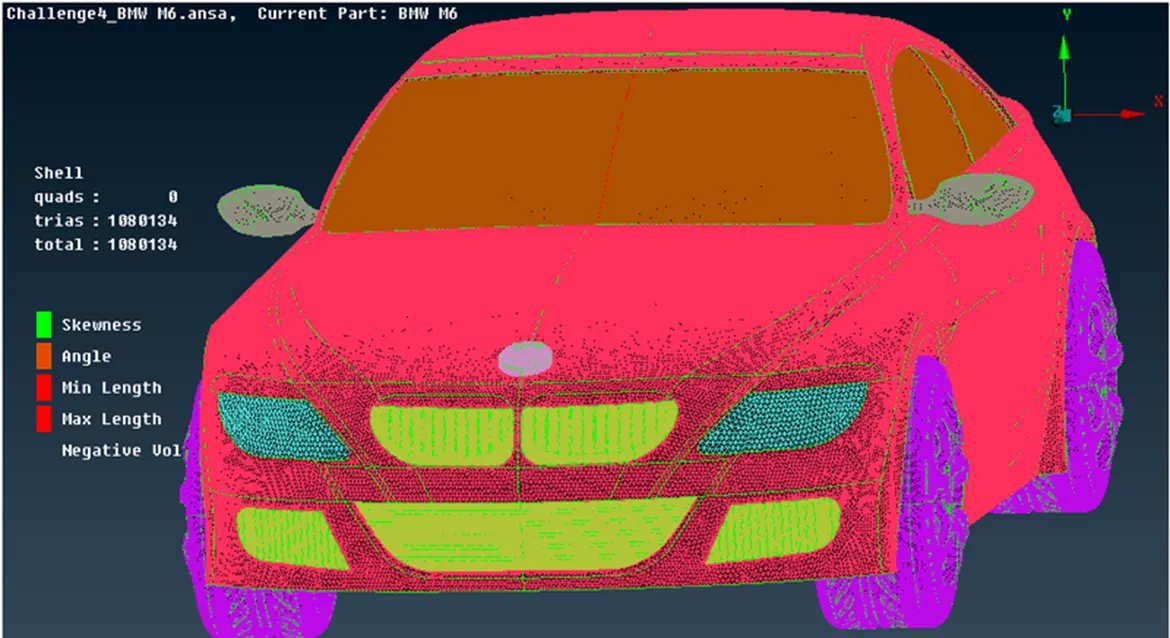
- Surface mesh on full car body after performing symmetry
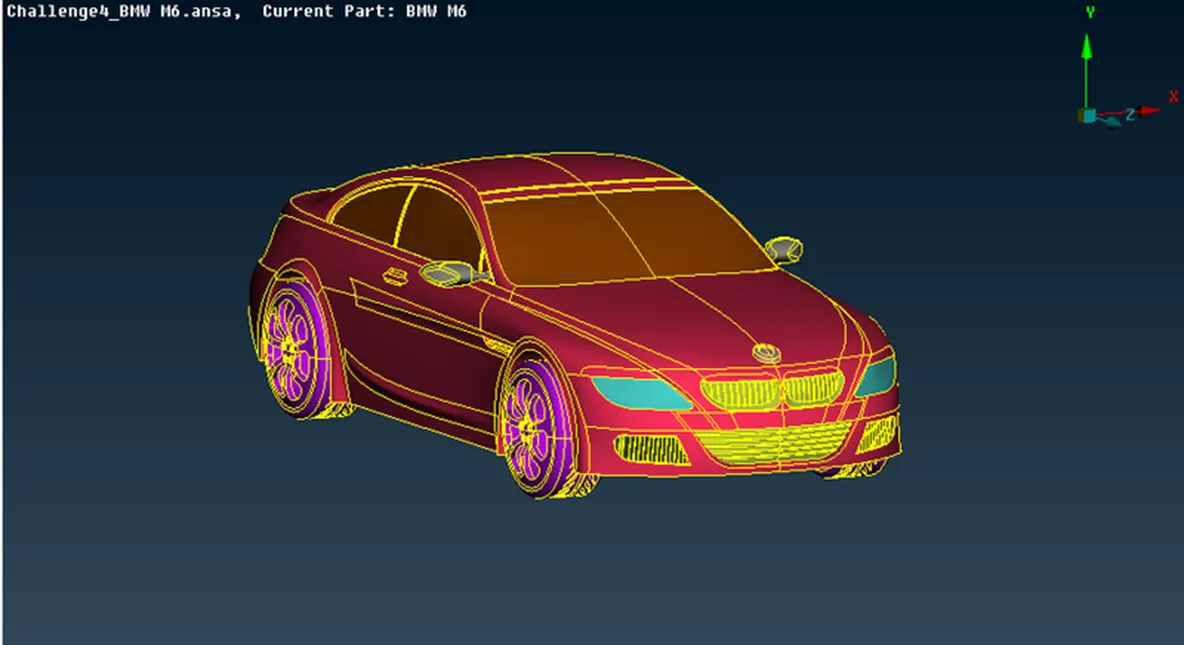
- Final car model
Creating wind tunnel
- To initiate the creation of wind tunnel surfaces, the first step involves generating reference points.
- In the topographic mode, opt for 'relative' under points. Create a point beneath the car by selecting a reference point and inputting the accurate values.
- Using relative points tool
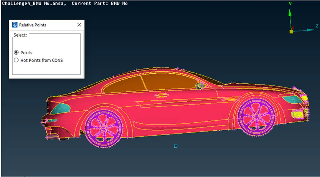
- By accurately calculating the wind tunnel dimensions, we can precisely establish the wind tunnel.
- The wind tunnel dimensions are as follows (standard distance of the tunnel with respect to the car model):
- Car model: 1306mm – x
- Front surface distance (from reference points): 5875mm - 4x
- Back surface distance (from reference points): 8480mm – 6x
- Top surface distance (from reference points): 4323mm – 3x
- Following the creation of the bottom surface, use curves as references for constraints. Subsequently, it is possible to delete all the unnecessary hot points and curves. f. Generate the remaining wind tunnel surfaces by utilizing the 'new surface' option.
- Image of the tunel:
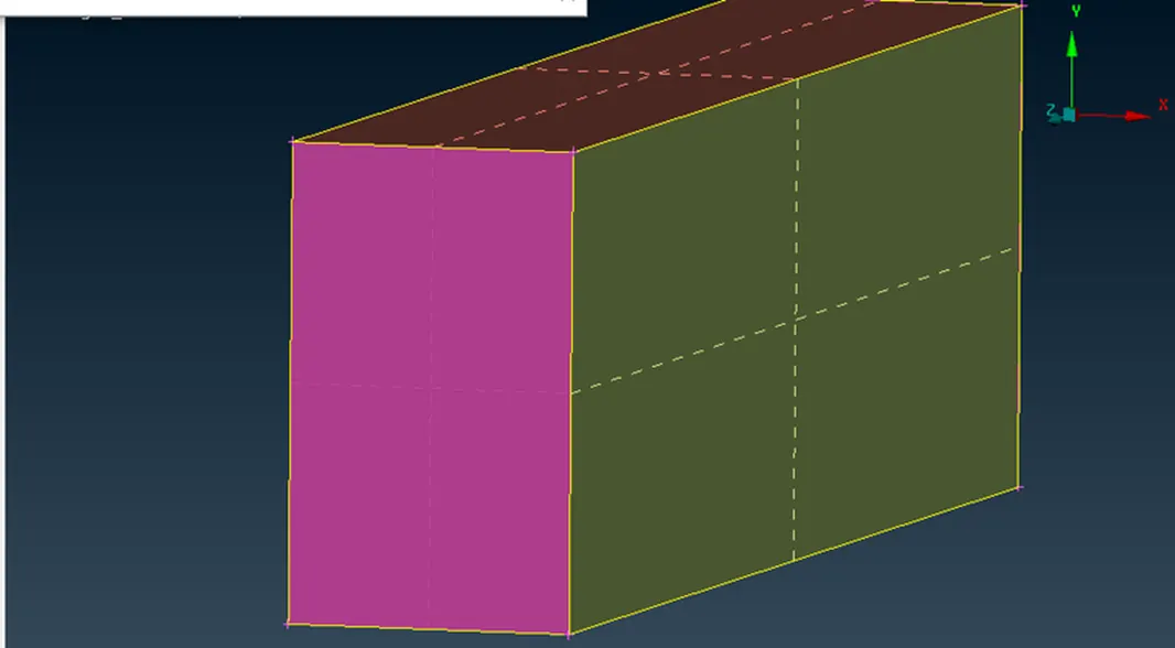
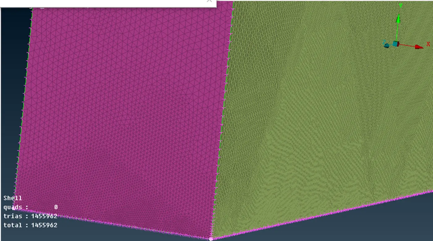
- Surface meshing is essential, and it should be applied with consideration for the mesh length near the car and in regions farther away from it.
- To achieve this, different mesh lengths should be applied to the bottom and top surfaces of the wind tunnel.
- Utilize the spacing option to implement a gradient in mesh length, transitioning from smaller lengths to larger ones.
- By following this approach, surface meshing can be effectively accomplished.
- Surface mesh of wind tunnel :
3. Volumetric mesh
- Focusing solely on the volume between the car model and the wind tunnel, it is advisable to delete unnecessary volumes from the car model.
- Considering the time constraints outlined in the challenge question, the volumetric meshing process, which typically takes 2-3 days, will not be executed.
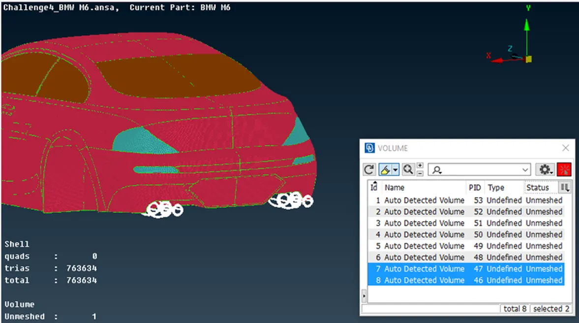
- Volume regions:
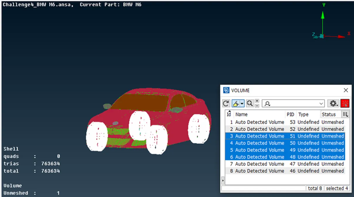
- Volume between wind tunnel and car model

- Car body single volume
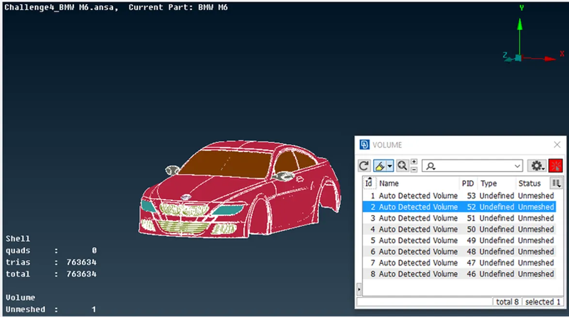
- Tyres volume
- Silencer volume
- Volume between wind tunnel and car model
- Since performing the volumetric mesh takes 2-3 days, volumetric mesh is not performed as given by the challenge question.
Learning outcomes:
- Acquired expertise in CFD meshing from the ground up.
- Employed various tools for topological clean-ups.
- Recognized the importance of double-consistency, eliminating unnecessary triple and single connections.
- Utilized symmetry to streamline work processes, resulting in accurate outcomes with reduced effort.
- Generated surfaces based on reference hot points through the use of relative points.
- Conducted surface meshing for diverse components, adapting to varying mesh lengths.
- Leveraged the spacing option in surface meshing to achieve diverse mesh lengths across surfaces.
- Employed the re-construct option to minimize off elements for manual editing.
Results:
This is a completed car model with wind tunnel simulation ANSA files. Click here
Conclusions:
- The BMW car model has undergone a thorough topology cleaning process and received an appropriate surface mesh.
- A wind tunnel has been constructed and meshed, taking into account the dimensions of the car model.
- Separate volumes have been generated for the car model's components, including the silencer and tires, due to their lack of attachment to the main body.
- A single volume encompassing the entire car body has been created to facilitate efficient volumetric mesh generation.
- Upon successful volumetric mesh generation, the wind tunnel volume model can be subjected to the necessary physics tests.