Week 8 - BlockMesh Drill down challenge
Fluid flow through a backward faced step
Introduction
Here we will be analyisng the fluid flow through a 2 Dimensional backward faced stepped channel and will study the effect of grading factor on the solution.
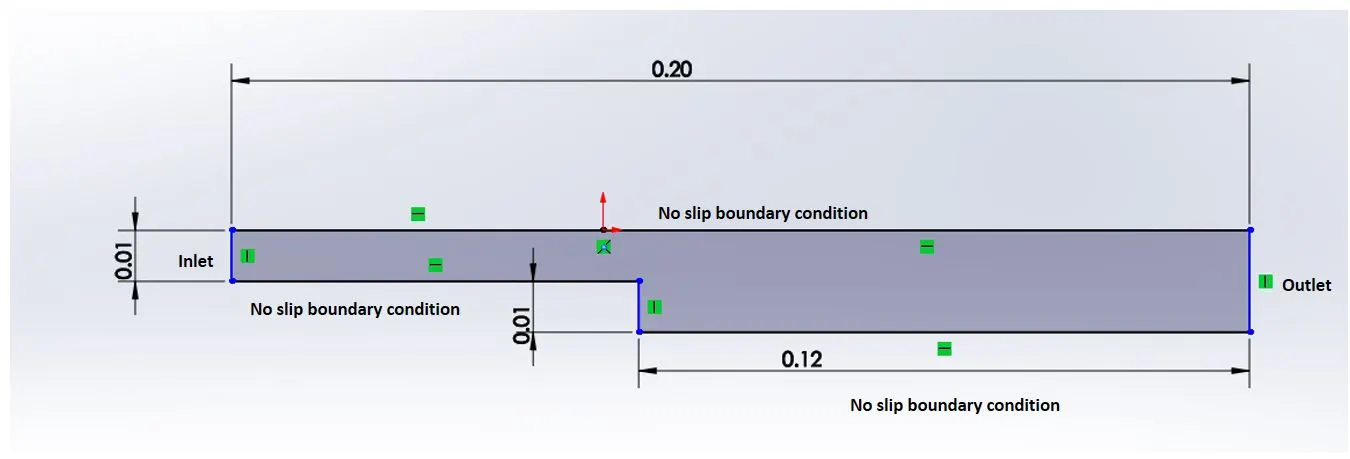
The above given diagram is our fluid domain and we have to model that in openFoam. Since near all the walls we need a fine mesh we will be dividing the entire fluid domain in to 5 blocks as given below.
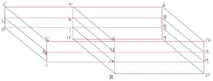
Meshing
Given Conditions are
- Number of cells along the x direction (longer dimension) = 200
- Number of cells along the y direction = 10
- Use a graded mesh. Grading factor near all walls should be 0.2 initially and then we will be considering grading factors of 0.5 and 0.8
Keeping this in mind we will be creating the geometry using blockMeshDict File located in system folder by enetring following command.
BlockMeshDict for Grading factor = 0.2
/*--------------------------------*- C++ -*----------------------------------*\
  =========                 |
  \\      /  F ield         | OpenFOAM: The Open Source CFD Toolbox
   \\    /   O peration     | Website:  https://openfoam.org
    \\  /    A nd           | Version:  8
     \\/     M anipulation  |
\*---------------------------------------------------------------------------*/
FoamFile
{
    version     2.0;
    format      ascii;
    class       dictionary;
    object      blockMeshDict;
}
// * * * * * * * * * * * * * * * * * * * * * * * * * * * * * * * * * * * * * //

convertToMeters 0.01;

vertices
(
    (0 0 0)
    (8 0 0)
    (8 0.5 0)
    (0 0.5 0)
    (8 1 0)
    (0 1 0)
    (20 1 0)
    (20 0.5 0)
    (20 0 0)
    (20 -1 0)
    (8 -1 0)
    (0 0 1)
    (8 0 1)
    (8 0.5 1)
    (0 0.5 1)
    (8 1 1)
    (0 1 1)
    (20 1 1)
    (20 0.5 1)
    (20 0 1)
    (20 -1 1)
    (8 -1 1)
);

blocks
(
    hex (0 1 2 3 11 12 13 14) (200 10 1) simpleGrading (1 5 1)
    hex (3 2 4 5 14 13 15 16) (200 10 1) simpleGrading (1 0.2 1)
    hex (2 7 6 4 13 18 17 15) (200 10 1) simpleGrading (5 0.2 1)
    hex (1 8 7 2 12 19 18 13) (200 10 1) simpleGrading (5 5 1)
    hex (10 9 8 1 21 20 19 12) (200 10 1) simpleGrading (5 5 1)
);

edges
(
);

boundary
(
    inlet
    {
        type patch;
        faces
        (
            (0 3 14 11)
            (3 5 16 14)
        );
    }
    outlet
    {
        type patch;
        faces
        (
            (7 18 17 6)
            (8 19 18 7)
            (9 20 19 8)
        );
    }
    topAndBottom
    {
        type wall;
        faces
        (
            (5 16 15 4)
            (4 15 17 6)
            (0 11 12 1)
            (10 1 12 21)
            (10 21 20 9)
        );
    }
    frontAndBack
    {
        type empty;
        faces
        (
            (0 1 2 3)
            (11 12 13 14)
            (3 2 4 5)
            (14 13 15 16)
            (2 7 6 4)
            (13 18 17 15)
            (1 8 7 2)
            (12 19 18 13)
            (10 9 8 1)
            (21 20 19 12)
        );
    }
);

mergePatchPairs
(
);

// ************************************************************************* //
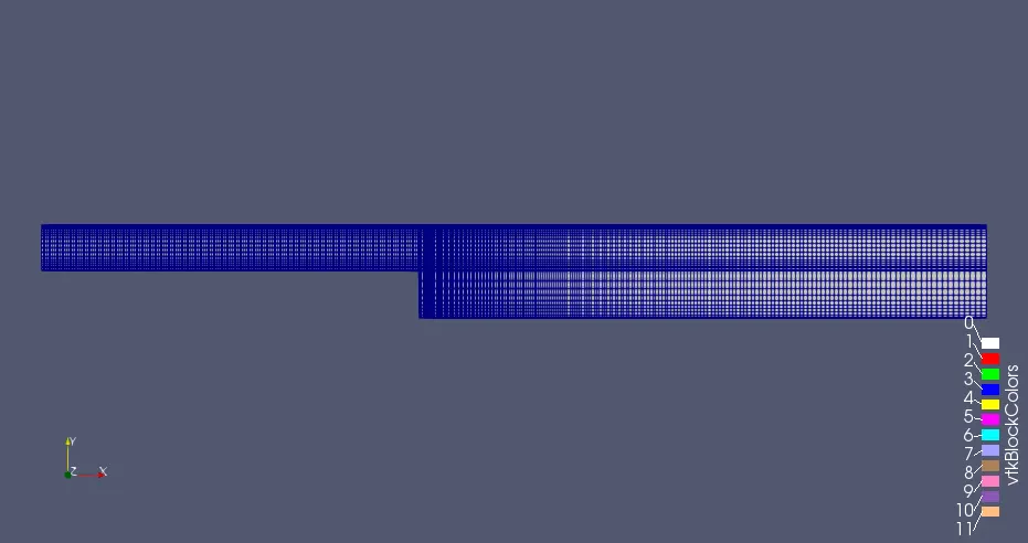
The Mesh structure for grading factor = 0.2 can be viewd using paraView and is given below.
For grading factor = 0.5 the portion in blockMeshDict can be modified as follows
blocks
(
    hex (0 1 2 3 11 12 13 14) (200 10 1) simpleGrading (1 2 1)
    hex (3 2 4 5 14 13 15 16) (200 10 1) simpleGrading (1 0.5 1)
    hex (2 7 6 4 13 18 17 15) (200 10 1) simpleGrading (2 0.5 1)
    hex (1 8 7 2 12 19 18 13) (200 10 1) simpleGrading (2 2 1)
    hex (10 9 8 1 21 20 19 12) (200 10 1) simpleGrading (2 2 1)
);
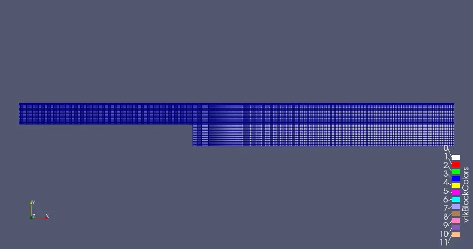
The Mesh structure for grading factor = 0.5 can be viewd using paraView and is given below.
For grading factor = 0.8 the portion in blockMeshDict can be modified as follows.
blocks
(
    hex (0 1 2 3 11 12 13 14) (200 10 1) simpleGrading (1 1.25 1)
    hex (3 2 4 5 14 13 15 16) (200 10 1) simpleGrading (1 0.8 1)
    hex (2 7 6 4 13 18 17 15) (200 10 1) simpleGrading (1.25 0.8 1)
    hex (1 8 7 2 12 19 18 13) (200 10 1) simpleGrading (1.25 1.25 1)
    hex (10 9 8 1 21 20 19 12) (200 10 1) simpleGrading (1.25 1.25 1)
);
The Mesh structure for grading factor = 0.8 can be viewd using paraView and is given below.
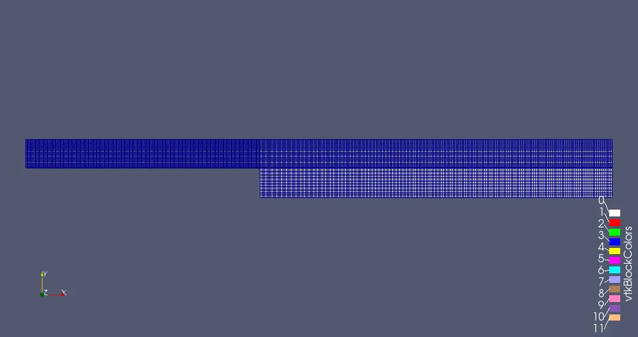
For grading factor = 1 the portion in blockMeshDict can be modified as follows.
blocks
(
    hex (0 1 2 3 11 12 13 14) (200 10 1) simpleGrading (1 1 1)
    hex (3 2 4 5 14 13 15 16) (200 10 1) simpleGrading (1 1 1)
    hex (2 7 6 4 13 18 17 15) (200 10 1) simpleGrading (1 1 1)
    hex (1 8 7 2 12 19 18 13) (200 10 1) simpleGrading (1 1 1)
    hex (10 9 8 1 21 20 19 12) (200 10 1) simpleGrading (1 1 1)
);
For grading factor = 1 the portion in blockMeshDict can be modified as follows.
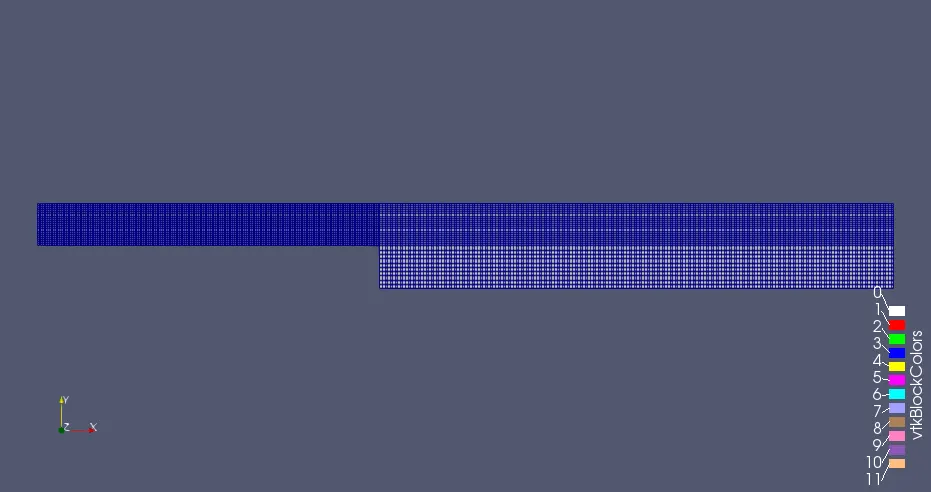
Setting Up the problem
The Control variables can be specified in ControlDict file and is set as given below.
start time = 0
end time = 0.005
Time Step = 0.00001
/*--------------------------------*- C++ -*----------------------------------*\
  =========                 |
  \\      /  F ield         | OpenFOAM: The Open Source CFD Toolbox
   \\    /   O peration     | Website:  https://openfoam.org
    \\  /    A nd           | Version:  8
     \\/     M anipulation  |
\*---------------------------------------------------------------------------*/
FoamFile
{
    version     2.0;
    format      ascii;
    class       dictionary;
    location    "system";
    object      controlDict;
}
application     icoFoam;

startFrom       startTime;

startTime       0;

stopAt          endTime;

endTime         0.005;

deltaT          0.00001;

writeControl    timeStep;

writeInterval   20;

purgeWrite      0;

writeFormat     ascii;

writePrecision  6;

writeCompression off;

timeFormat      general;

timePrecision   6;

runTimeModifiable true;


// ************************************************************************* //
The Velocity initial conditions can be given in U File and is set as given below.
inlet velocity = 1 m/s
/*--------------------------------*- C++ -*----------------------------------*\
  =========                 |
  \\      /  F ield         | OpenFOAM: The Open Source CFD Toolbox
   \\    /   O peration     | Website:  https://openfoam.org
    \\  /    A nd           | Version:  8
     \\/     M anipulation  |
\*---------------------------------------------------------------------------*/
FoamFile
{
    version     2.0;
    format      ascii;
    class       volVectorField;
    object      U;
}
// * * * * * * * * * * * * * * * * * * * * * * * * * * * * * * * * * * * * * //

dimensions      [0 1 -1 0 0 0 0];

internalField   uniform (0 0 0);

boundaryField
{
    inlet
    {
        type            fixedValue;
        value           uniform (1 0 0);
    }
    outlet
    {
        type            zeroGradient;
    }
    topAndBottom
    {
        type            noSlip;
    }
    frontAndBack
    {
        type            empty;
    }
}

// ************************************************************************* //
The Pressure boundary conditions can be specified in p file and is given as follows.
/*--------------------------------*- C++ -*----------------------------------*\
  =========                 |
  \\      /  F ield         | OpenFOAM: The Open Source CFD Toolbox
   \\    /   O peration     | Website:  https://openfoam.org
    \\  /    A nd           | Version:  8
     \\/     M anipulation  |
\*---------------------------------------------------------------------------*/
FoamFile
{
    version     2.0;
    format      ascii;
    class       volScalarField;
    object      p;
}
// * * * * * * * * * * * * * * * * * * * * * * * * * * * * * * * * * * * * * //

dimensions      [0 2 -2 0 0 0 0];

internalField   uniform 0;

boundaryField
{
    inlet
    {
        type            zeroGradient;
    }

    outlet
    {
        type            fixedValue;
        value           uniform 0;
    }

    topAndBottom
    {
        type            zeroGradient;
    }

    frontAndBack
    {
        type            empty;
    }
}

// ************************************************************************* //
Results
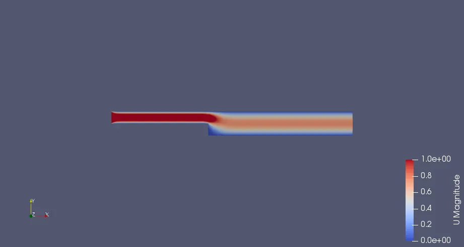
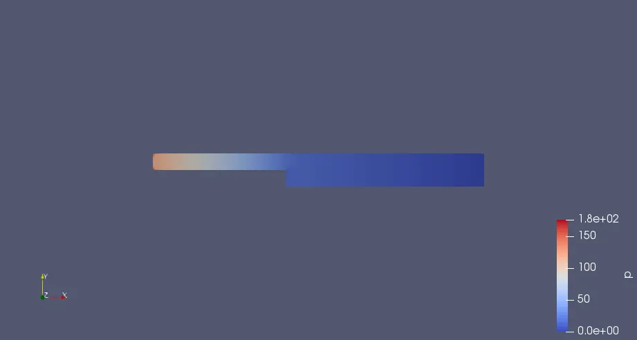
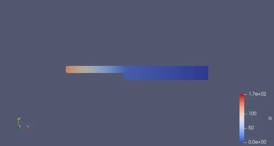
The icoFoam solver is used to Solve the problem. The Velocity Pressure distribution for all the cases are given below.
Velocity Distribution
Grading Factor = 1
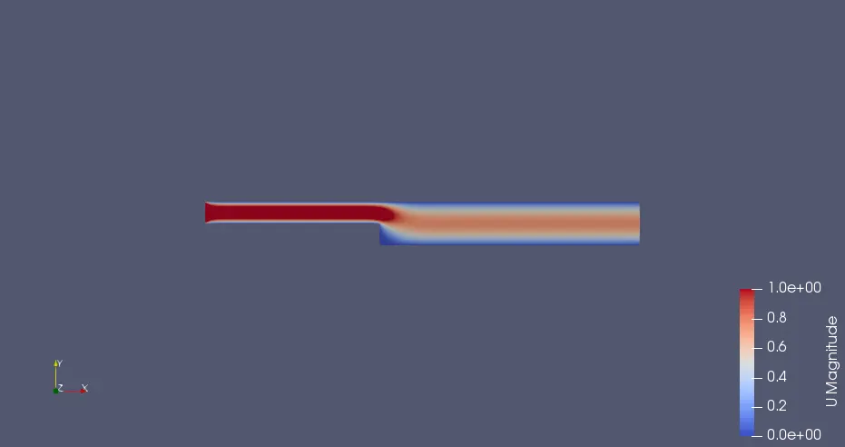
Grading Factor = 0.2
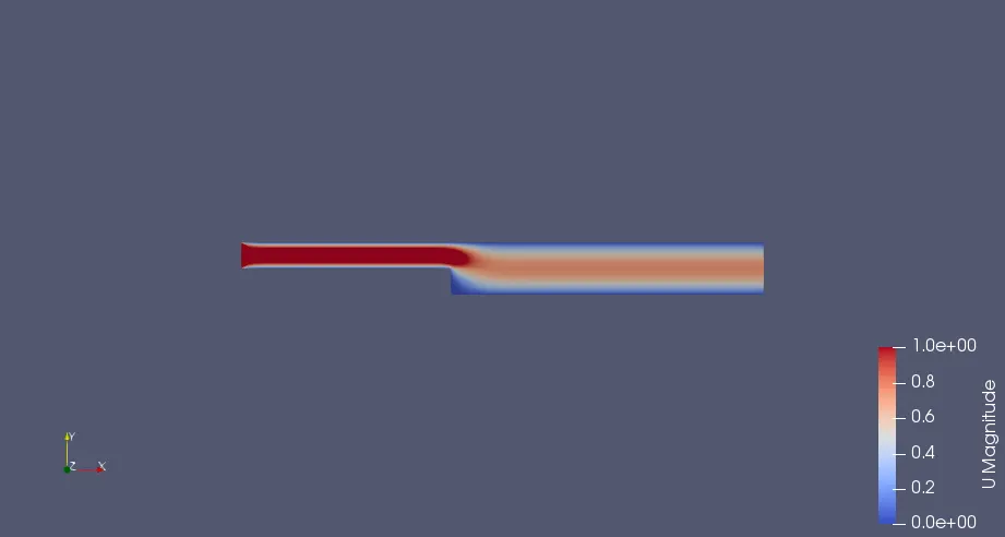
Grading Factor = 0.5
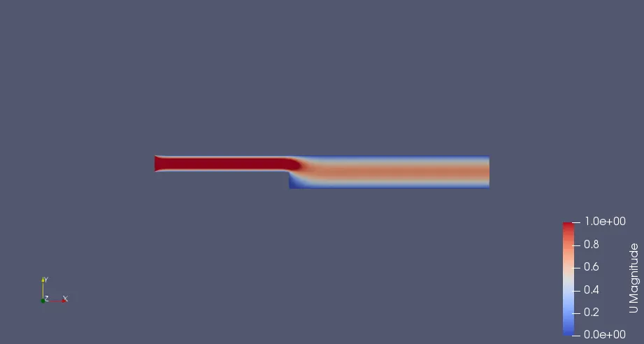
Grading Factor = 0.8
Pressure Distribution
Grading Factor = 0.2
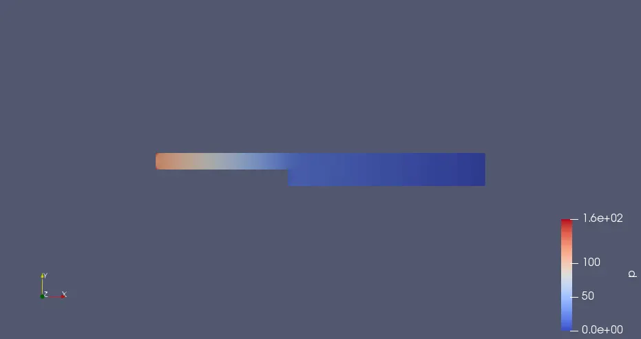
Grading Factor = 0.2
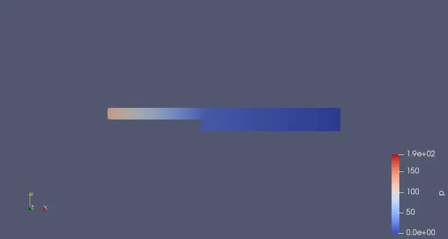
Grading Factor = 0.5
Grading Factor = 0.8
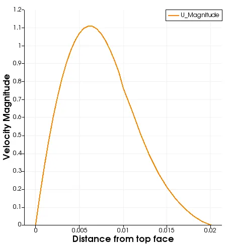
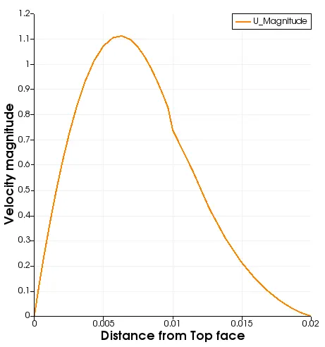
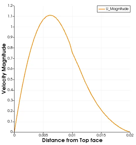
Line Plot of velocity at X = 0.085
Grading factor = 1
Grading factor = 0.2
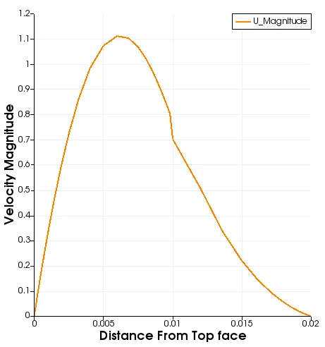
Grading factor = 0.5
Grading factor = 0.8
Conclussion
The given problem has been solved using OpenFoam and all the results has been obtained. For the sake of comaprison we will be comparing velocity values at a particular location near the topwall (0.00998 m downside the top face) and at distance of 0.085 from the inlet for all the cases.
| Grading Factor | 0.2 | 0.5 | 0.8 | 1 |
| Velocity | 0.0073757 | 0.0070767 | 0.0069129 | 0.0068324 |
These values has been obtained by exporting the data to CSV file. here its clearly visible that as expansion ratio increases Velocity value decreses, So to get accuarate results we should employ finer mesh near the wall where wall shear stress is having a key role..
I am attaching The zipped case folder below.