Week 4 Challenge : CFD Meshing for BMW car
Question:
For the given model, check and solve all geometrical errors on half portion and Assign appropriate PIDs. Perform meshing with the given Target length and element Quality criteria. After meshing the half model, Do symmetry to the other side.
- Target lengths for the different parts of a model are as follows:
- Body - 3 mm
- Lights - 4 mm
- Grills - 1 mm
- Rims and Tyres - 2 mm
- Optical Rear view mirror - 2 mm
- Window - 2 mm
- Silencer - 3 mm
- Logo - 1 mm
(Note: Kindly take reference of videos for other Quality criteria)
Meshing Wind tunnel volume with tetra elements may take up to 2 days. So that is not compulsory to perform. i.e. Model can be submitted after performing surface mesh to Wind tunnel surfaces. Write a detailed report for the same.
Note: All the 2D elements(Trias) in your model should clear the quality criteria (i.e. Off elements should be zero). Depending upon this you will be awarded marks.
Answer:
model:
https://drive.google.com/file/d/1PrGtbwF0Jhty_8lSCL1ubJUBSghjRnxZ/view?usp=sharing
Aim:
The primary objectives are to identify and rectify any geometrical errors present in the half model, create and assign appropriate PIDs, perform surface meshing with prescribed target lengths based on PIDs, and finally do the symmetry on the other side.
Introduction:-
The precise alignment of geometrical components holds the utmost significance in computational simulations and analysis, especially in domains like fluid dynamics and structural analysis. Meshing plays a pivotal role as it acts as a link between the continuous geometry of the model and the discrete numerical calculations executed by simulation software. This report outlines the approach utilized to rectify geometrical inaccuracies, produce surface meshes, allocate PIDs, and construct volume meshes for diverse components within the given model.
Procedure:
<!-- [if !supportLists]-->1. <!--[endif]-->Geometrical Error Correction: The first step in the meshing process involves identifying and rectifying geometrical errors present in the given model.
Open the model in the ANSA pre-processor.
<!-- [if gte vml 1]>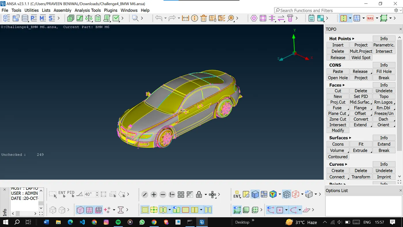
And check for the geometrical errors present in the model.
This type of error can be solved using the fine option but will take a long time to do it so we will do it by going in mesh and giving a mesh length. So that it will be done in one shot.
<!-- [if gte vml 1]>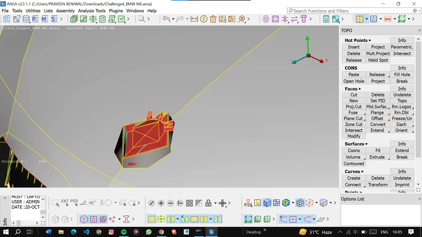
Done with the refinement of the cons.
<!-- [if gte vml 1]>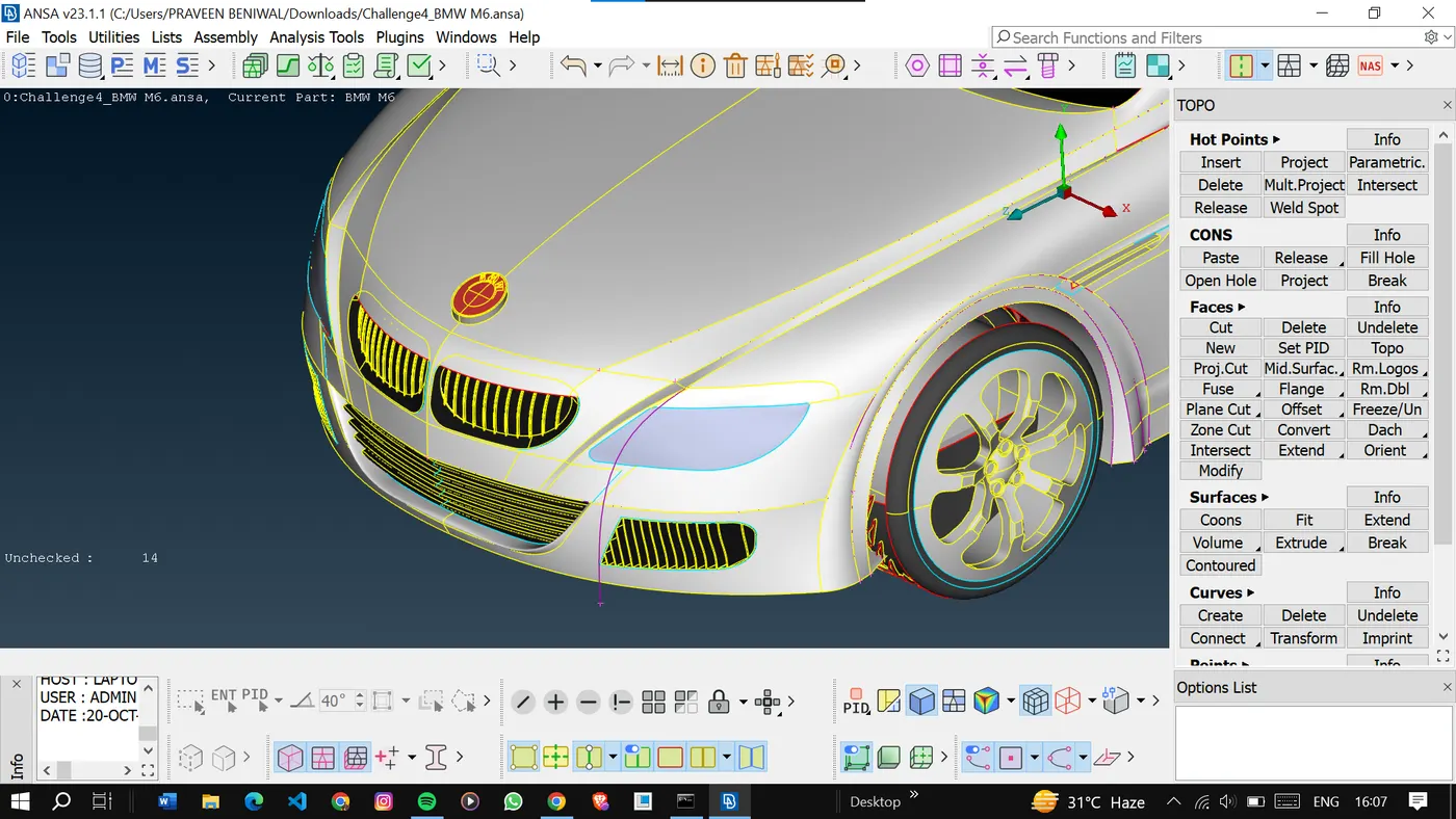
Now we try to solve the other errors present in the geometry.
As we can see there are so many single cons present here.
<!-- [if gte vml 1]>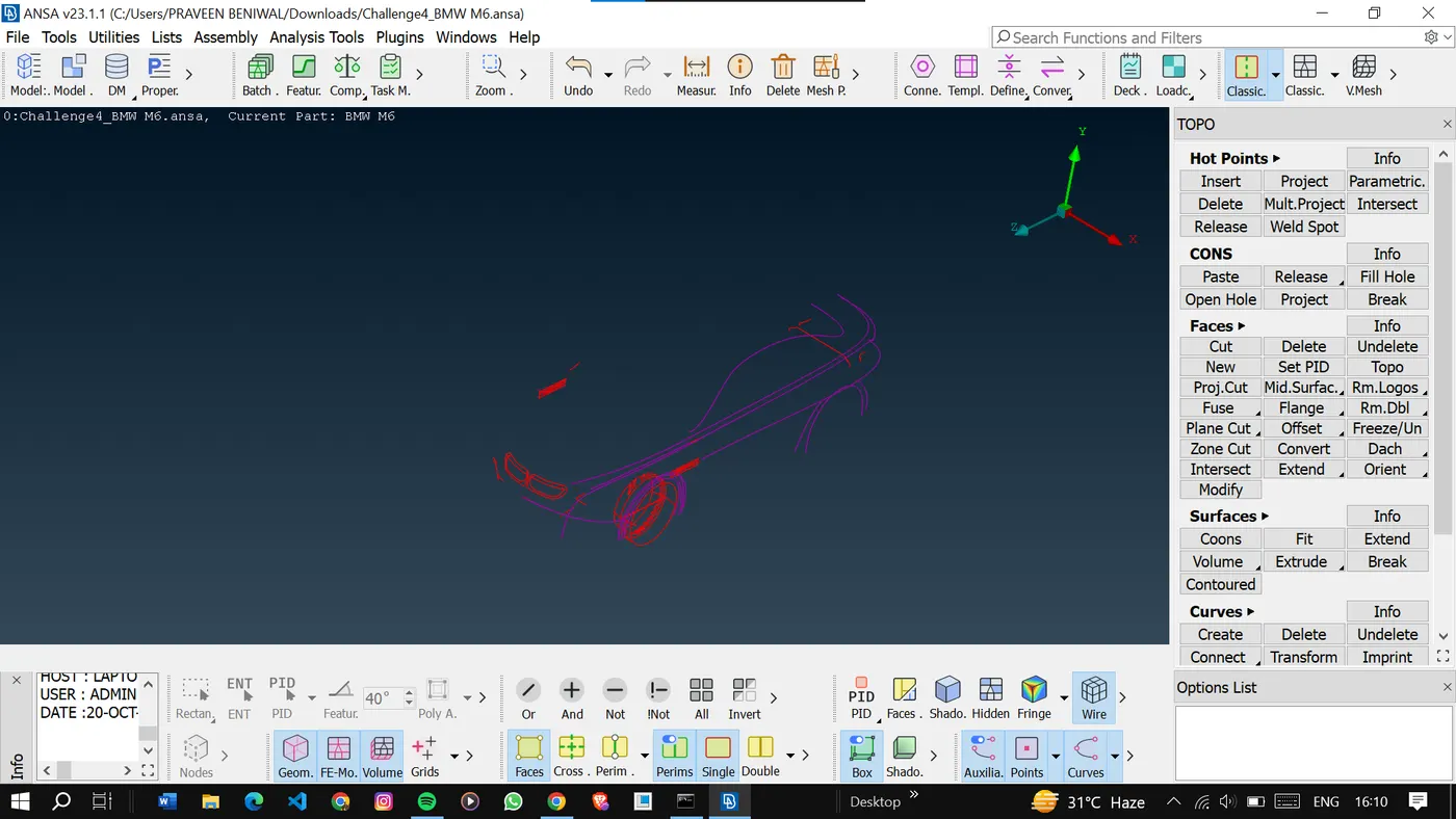
So to solve the geometry we will take only half model and delete the rest.
<!-- [if gte vml 1]>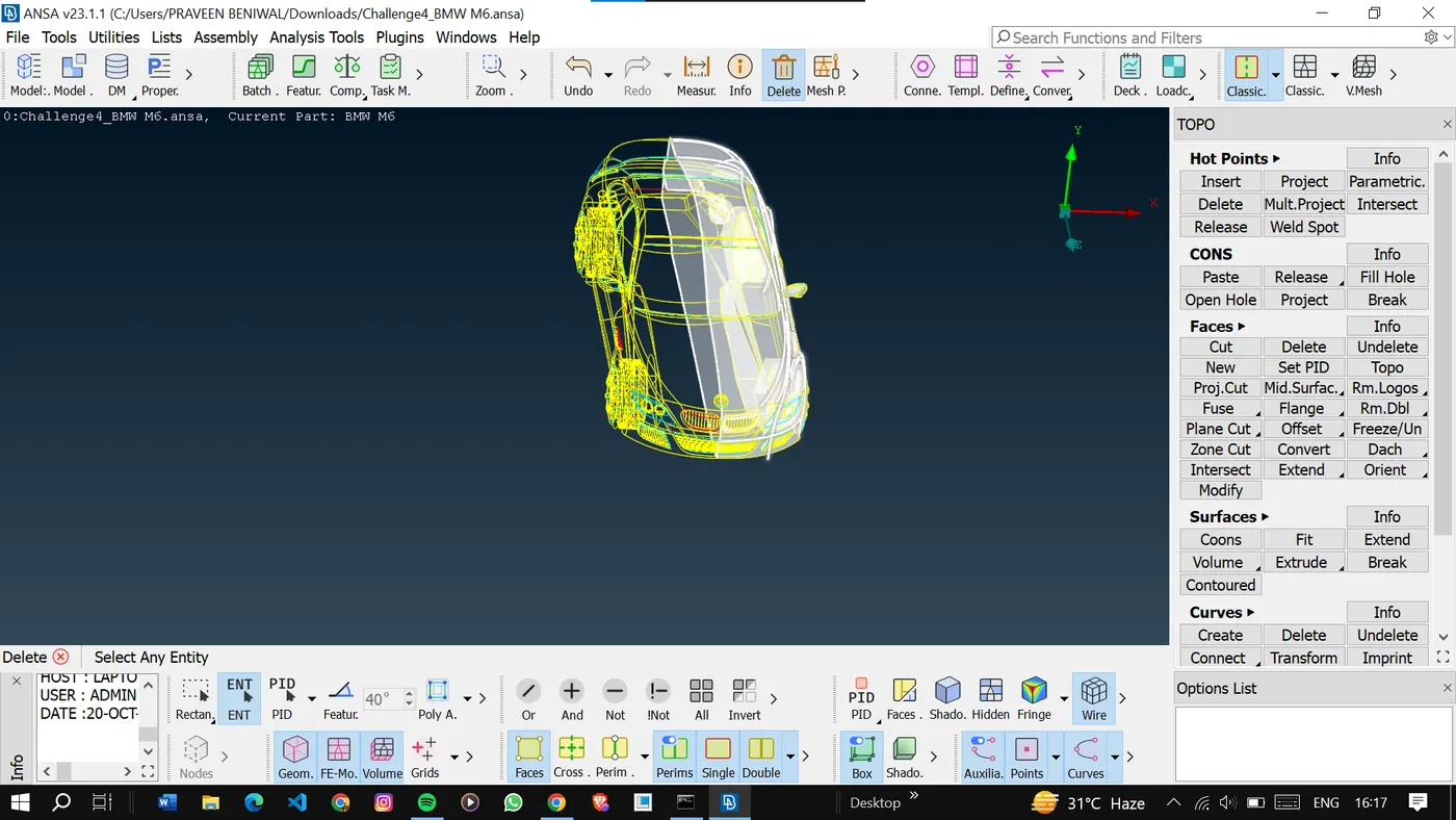
Here we're left with only half of the model.
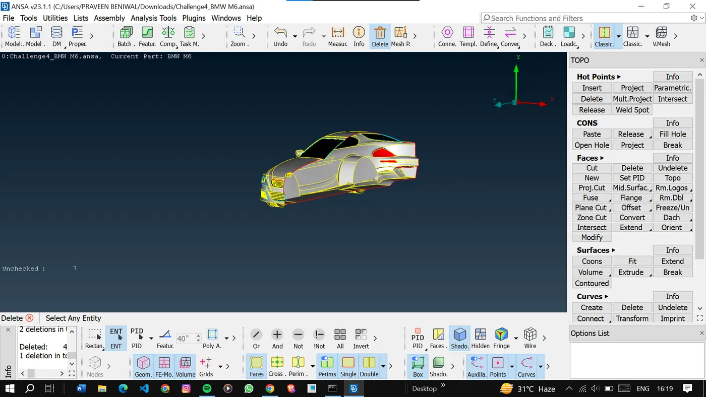
Now it's time for geometric cleanup.
We will try to solve the single cons and some irregular surfaces by different techniques and also try to convert the whole model into a single shell so that we can perform volumetric mesh on the model.
<!-- [if gte vml 1]>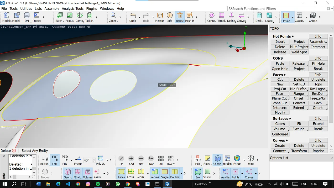
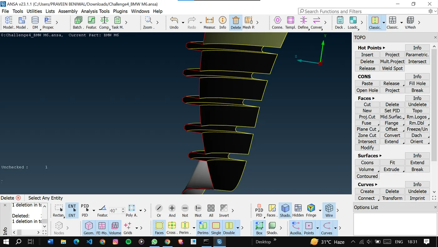
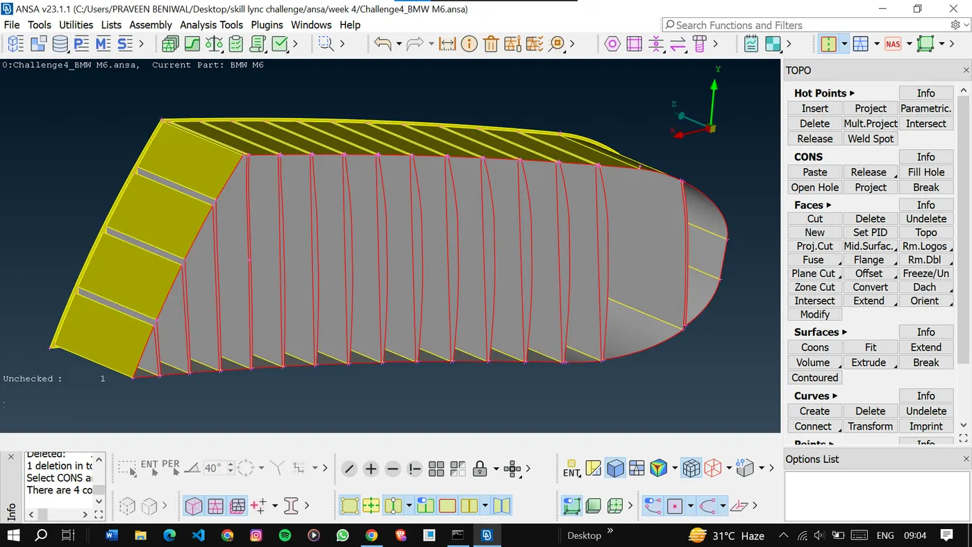
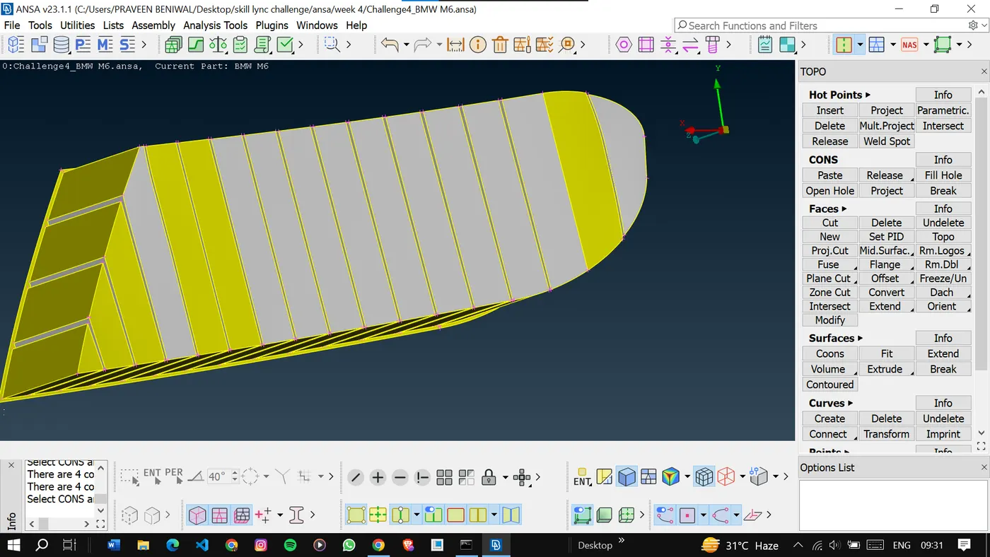
As we can see here we are only left with one single con and no triple con present in this section of the model.
<!-- [if gte vml 1]>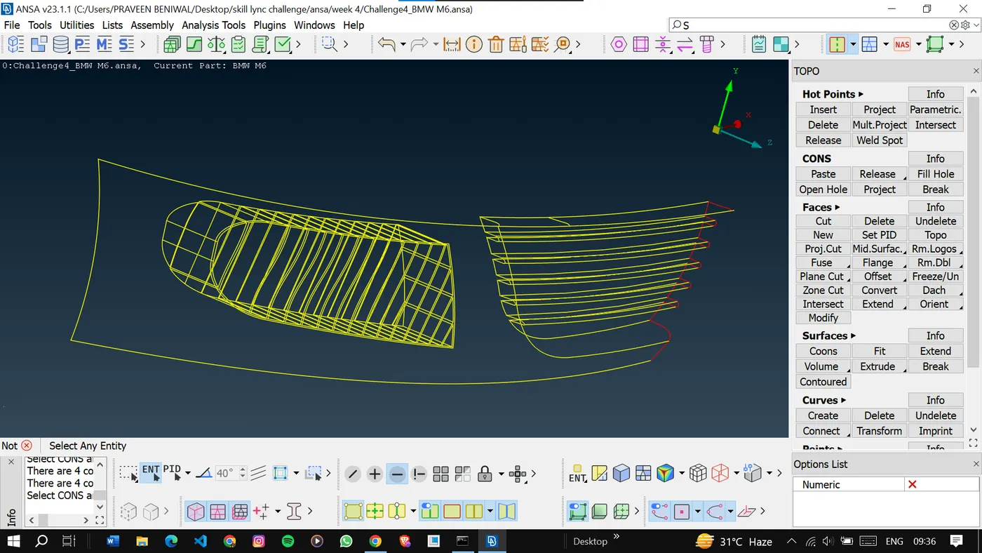
Similarly, we will perform the clean-up on the rest of the model.
These types of small surfaces are more critical so to work with these try to isolate them first and then proceed to next to avoid other interference.
<!-- [if gte vml 1]>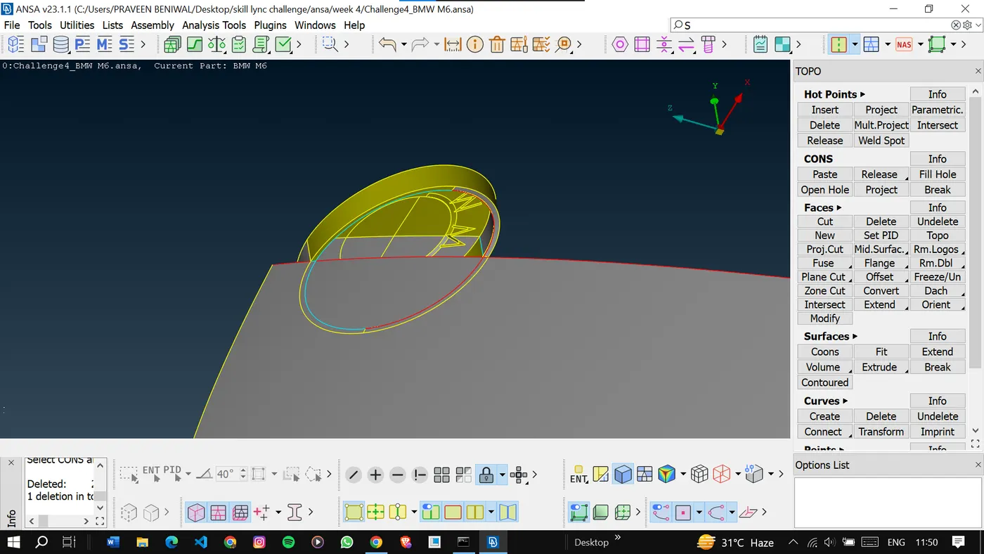
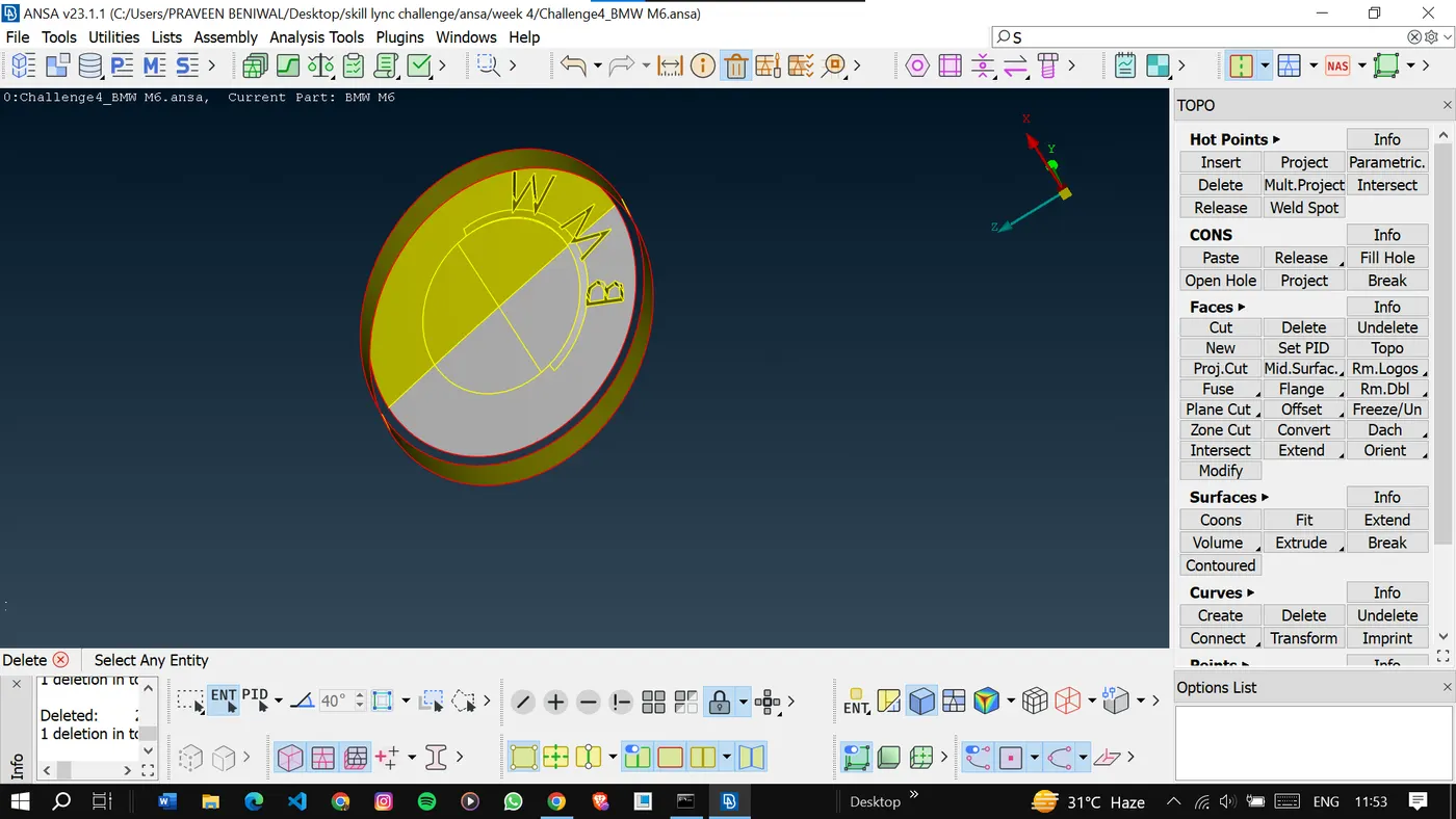
Delete the unwanted surfaces.
<!-- [if gte vml 1]>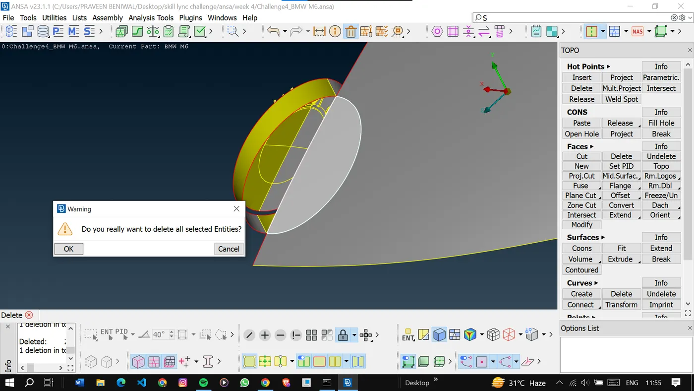
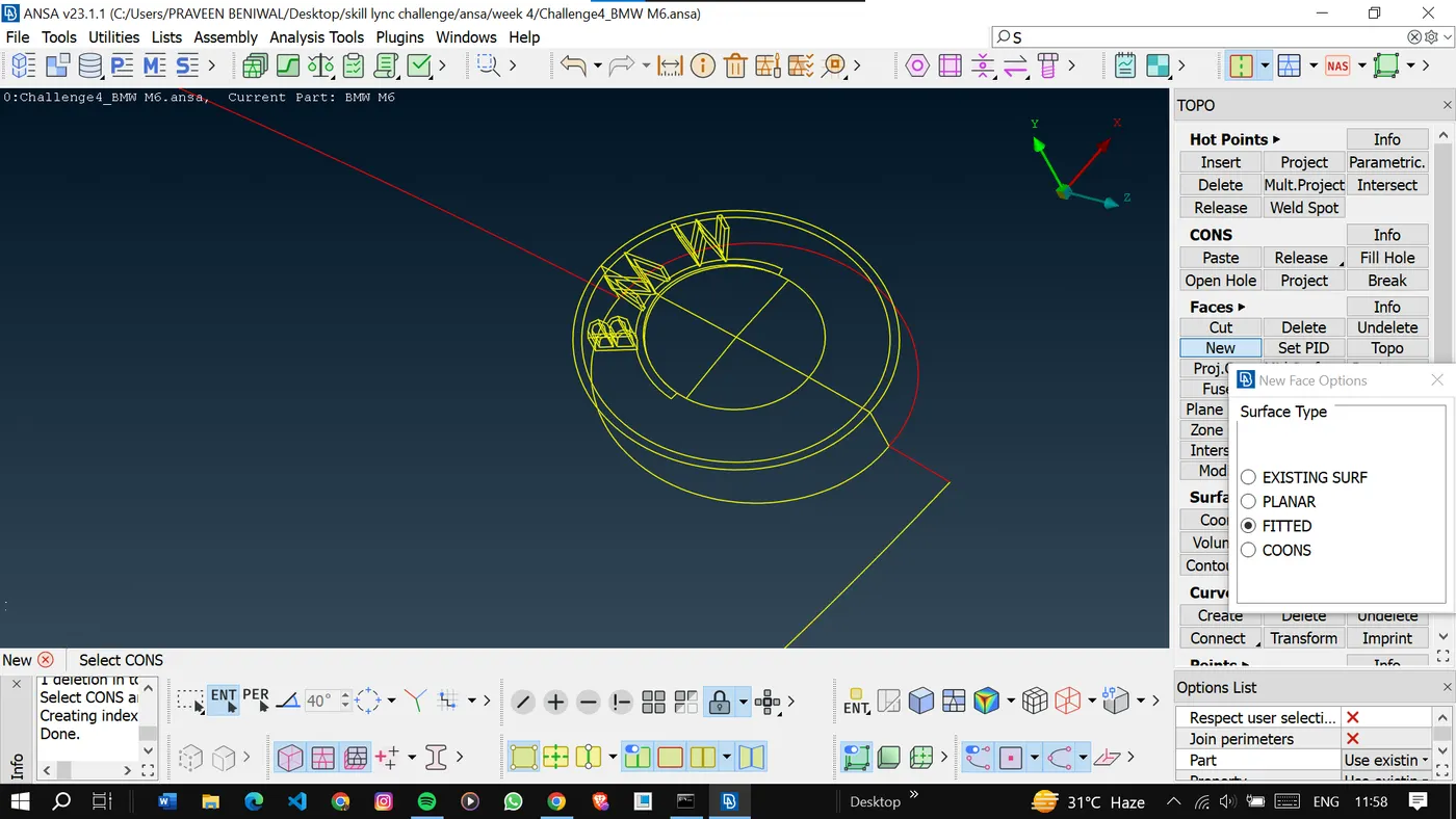
Also, delete the inner surfaces of the windshield to get a single volume inside the car.
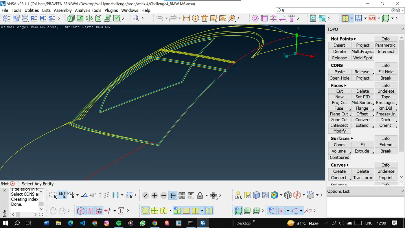
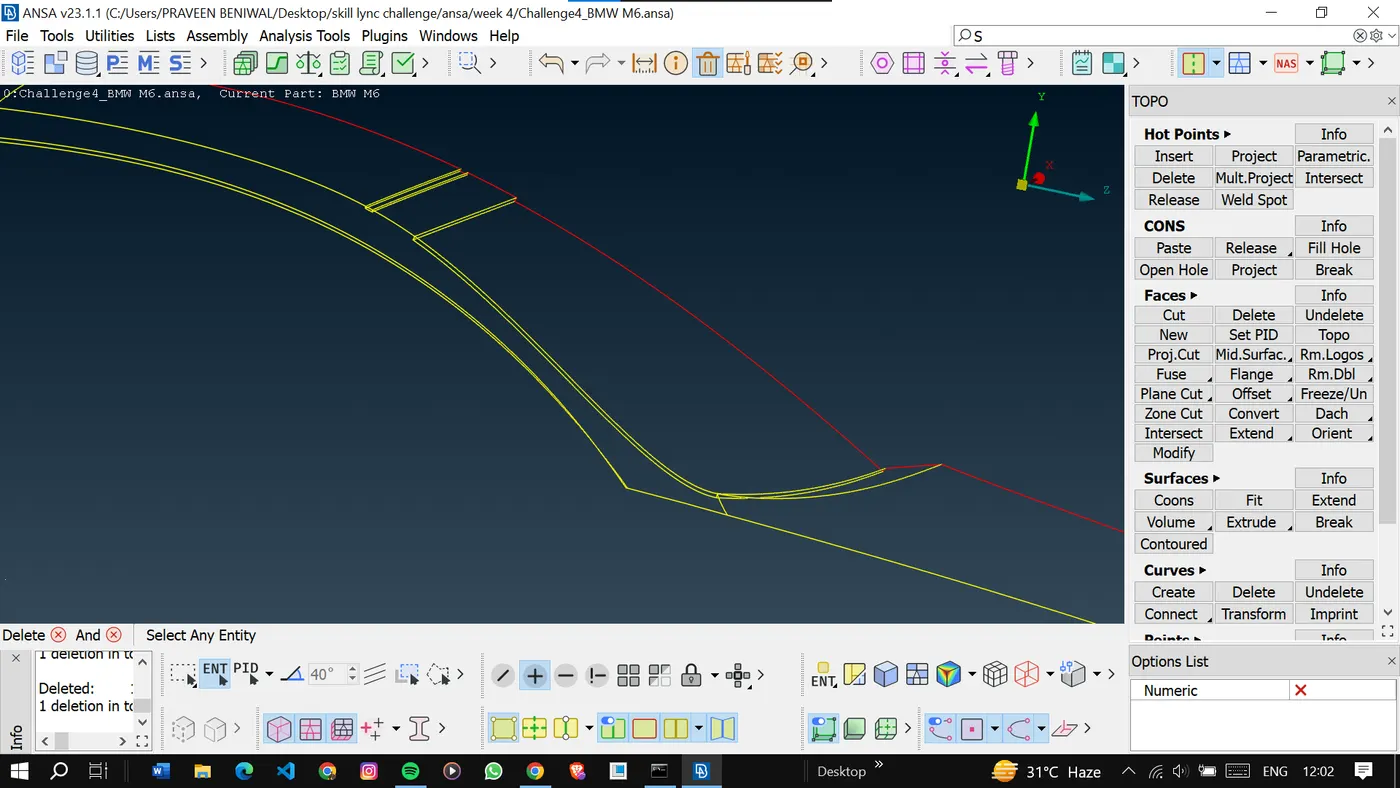
As we are done with the solution of the front and windshield area now go for the side panel and back side.
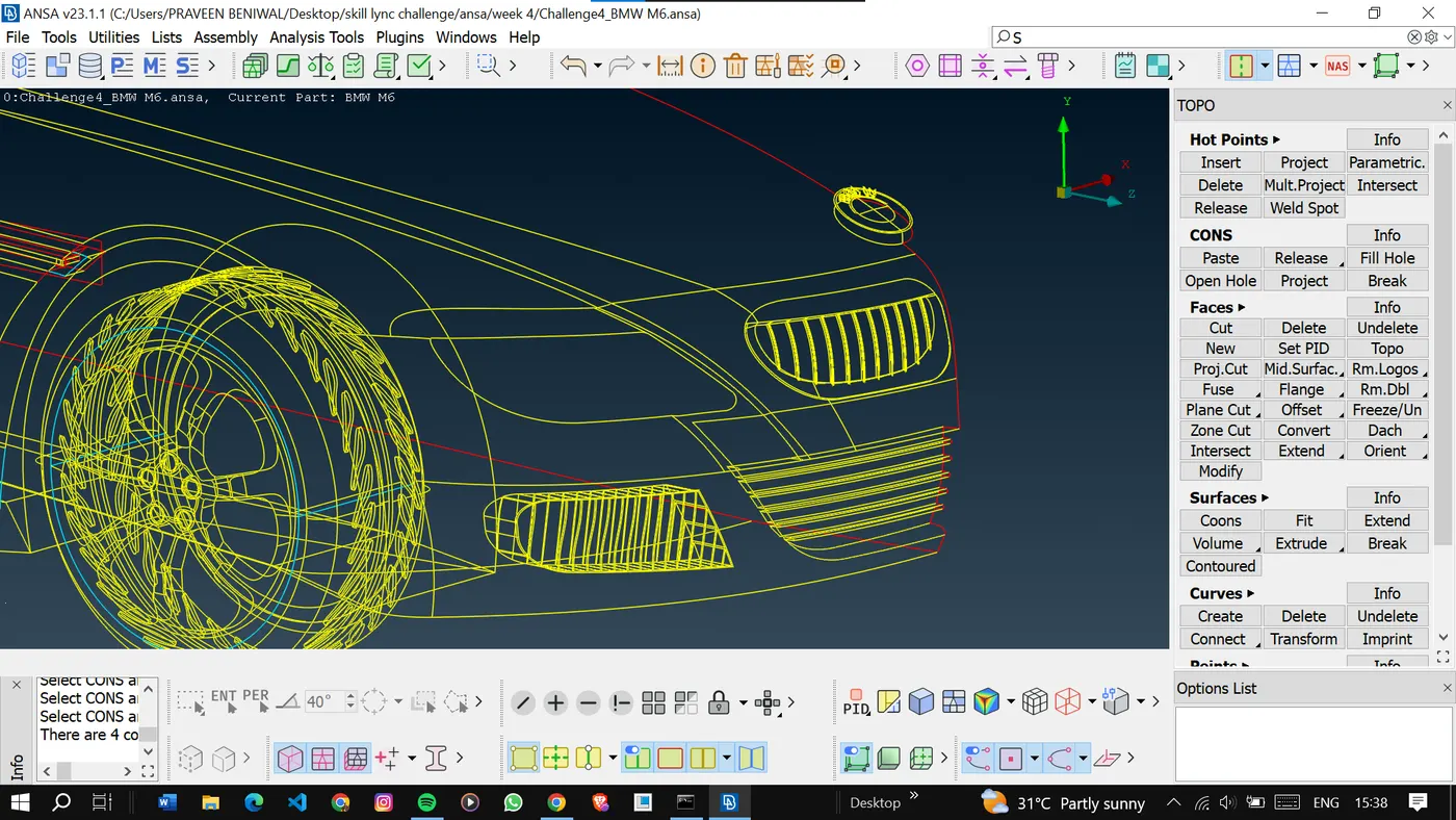
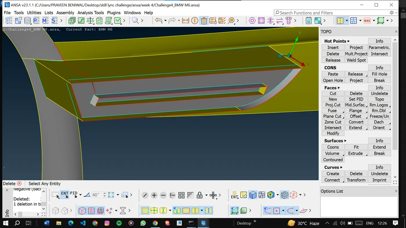
Here side panel looks good to go.
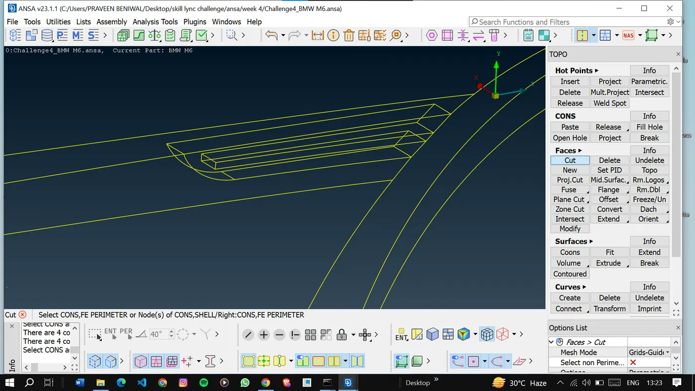
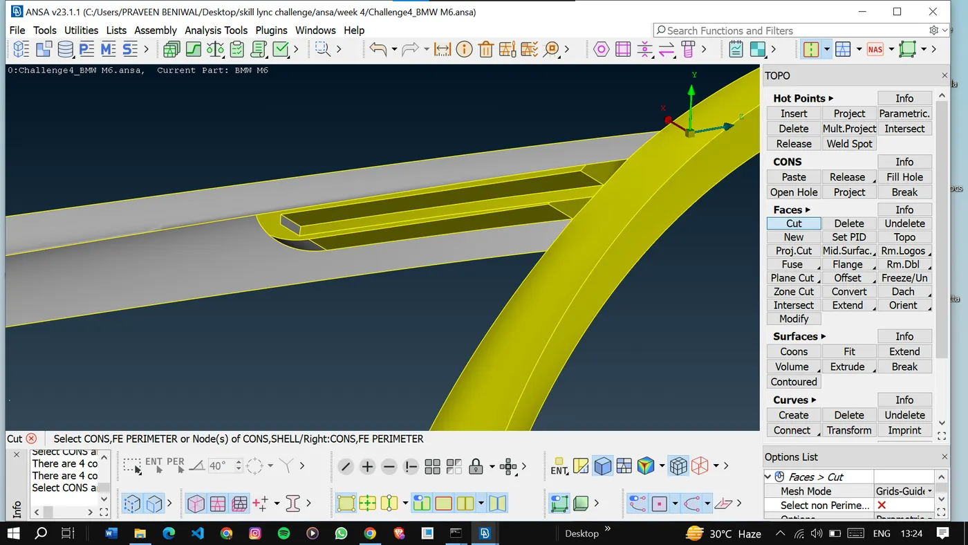
The side mirror is also important to make a single volume so we will solve this as well.
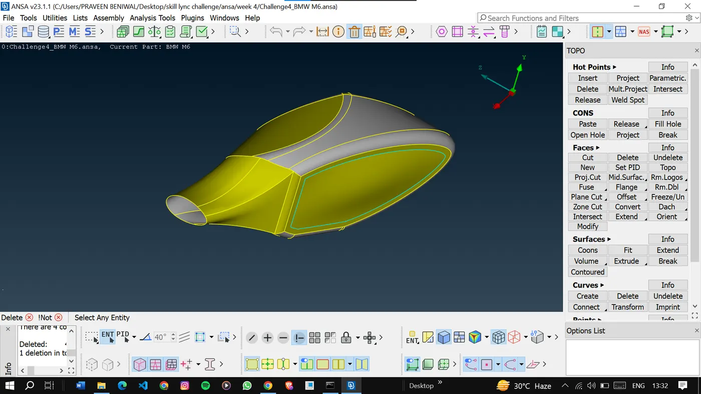
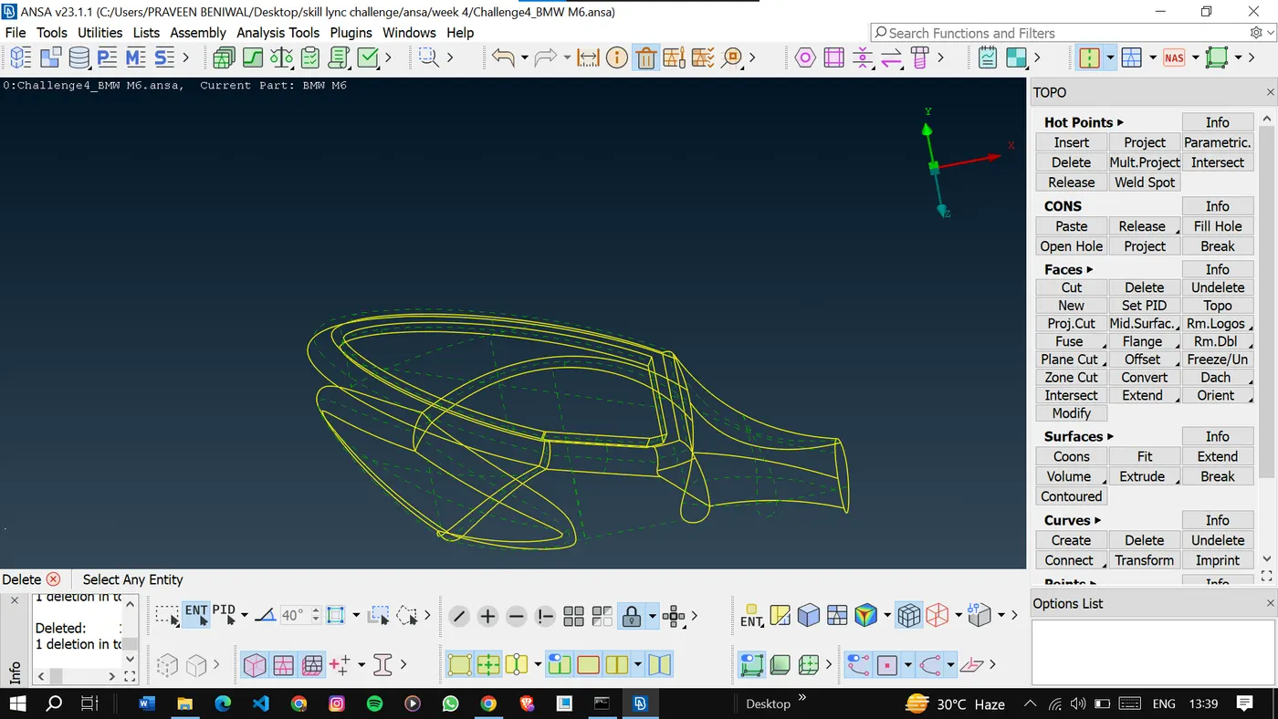
Solve the tyre also even though it’s a different volume but necessary for meshing.
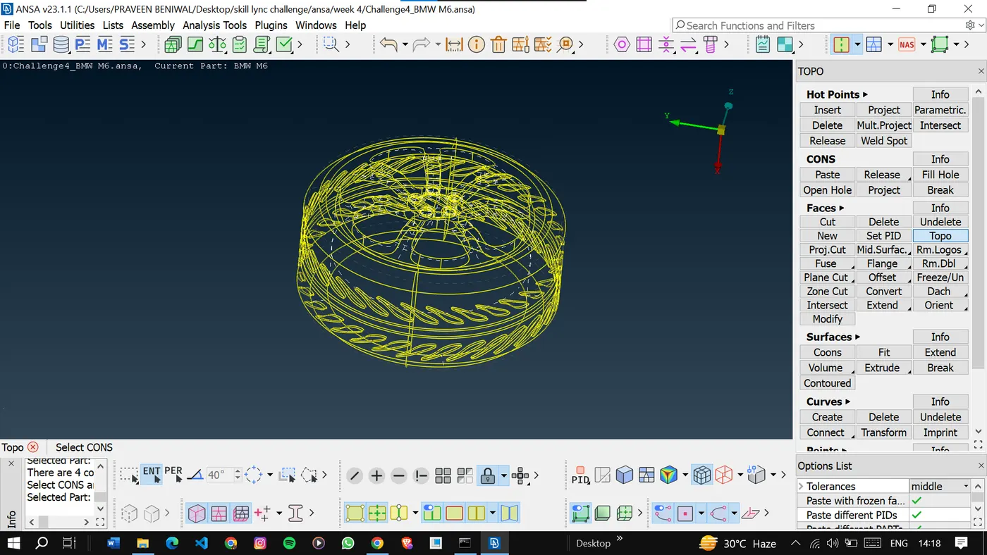
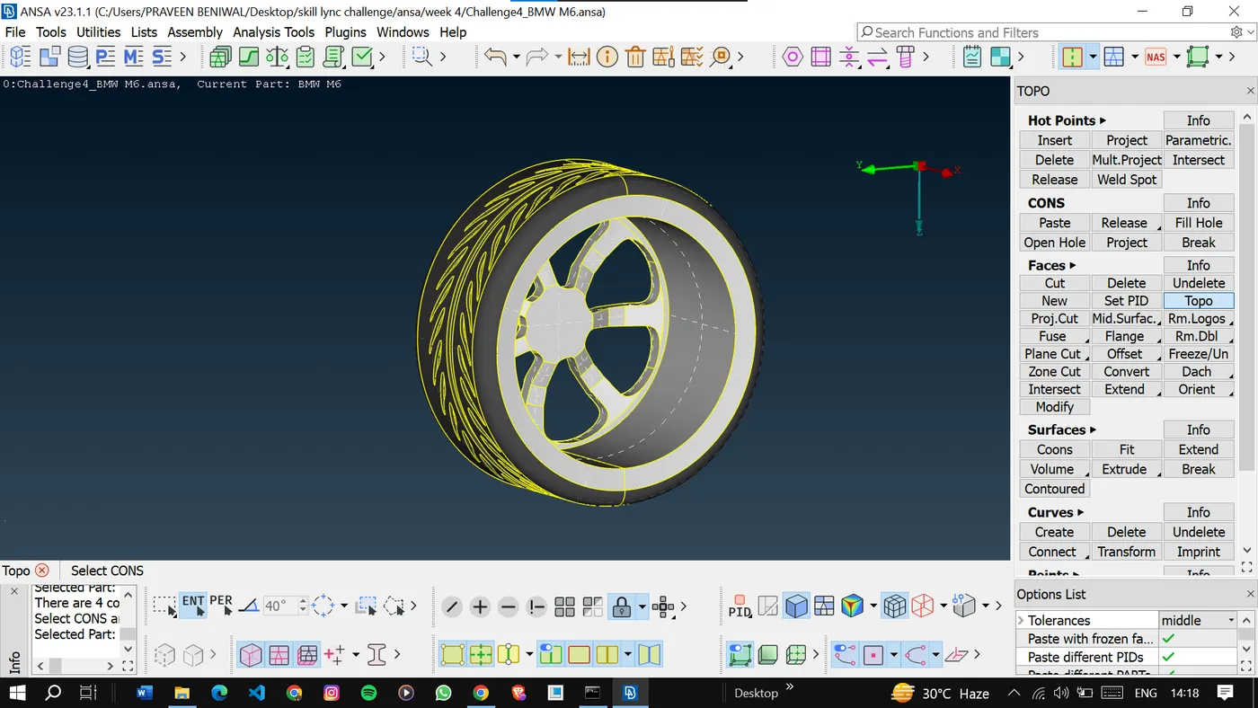
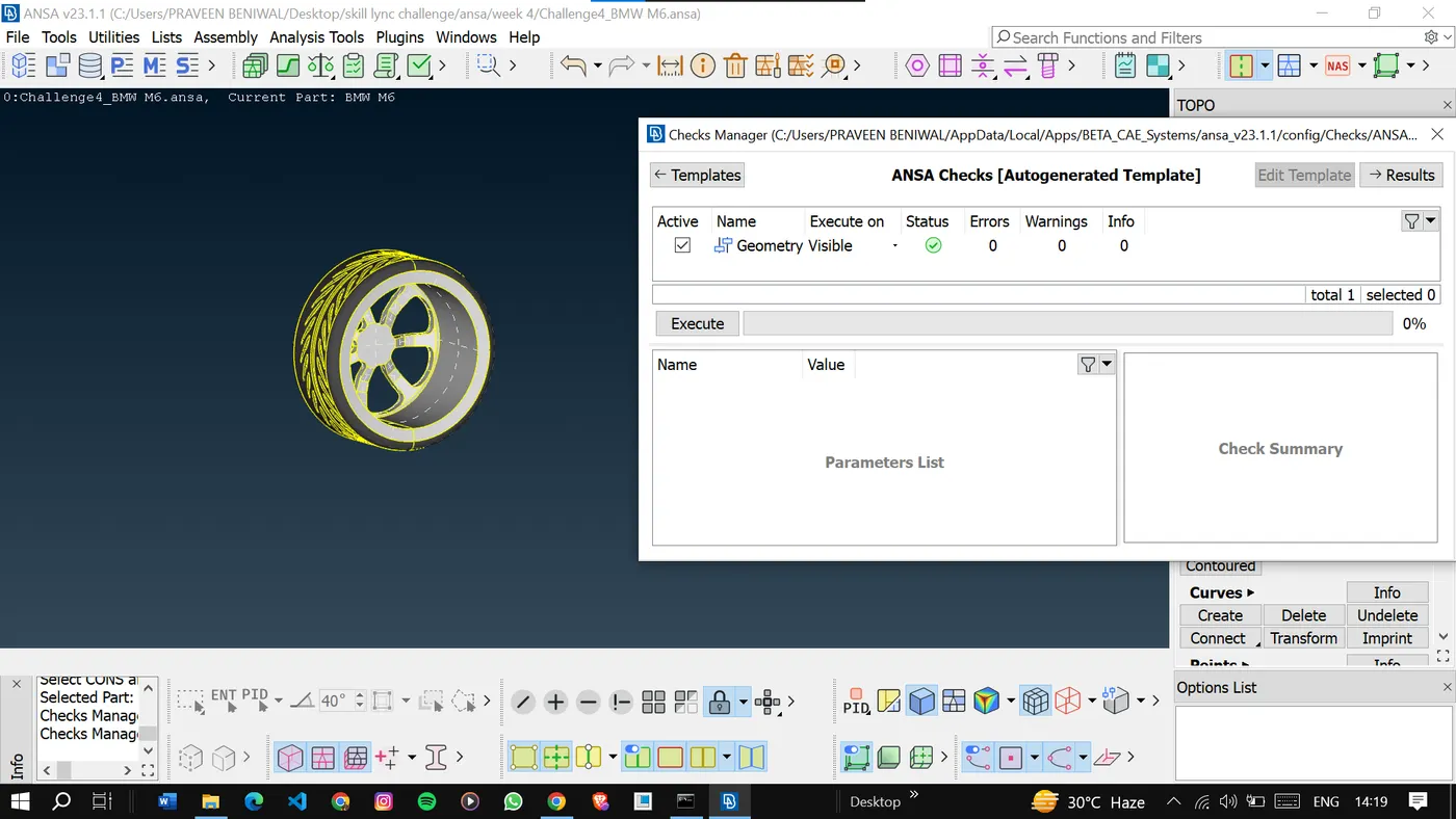
Go for geometry checks as the surfaces are tiny.
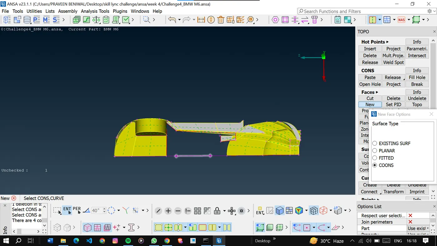
Now we will try to solve the base of the car body as it contains so many irregularities.
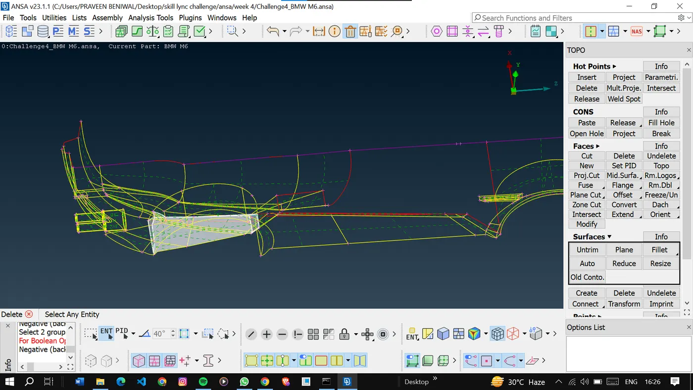
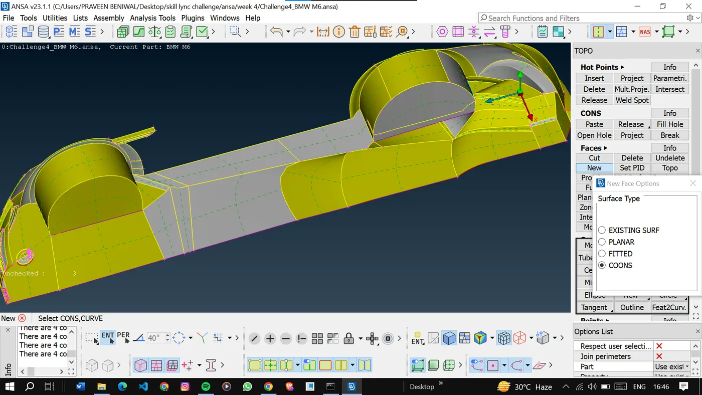
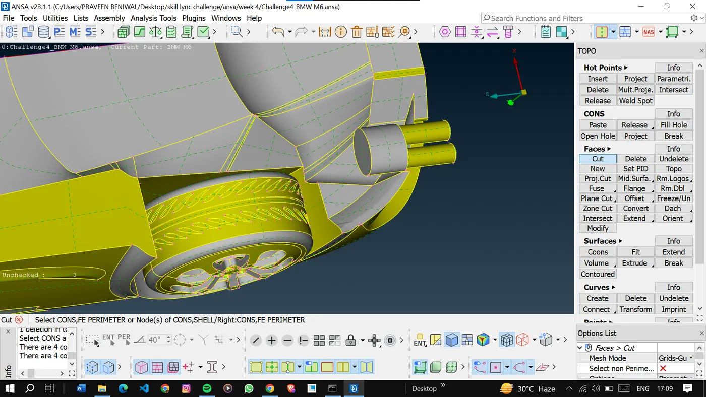
After solving all the errors we are only left with single cons present at the partition.
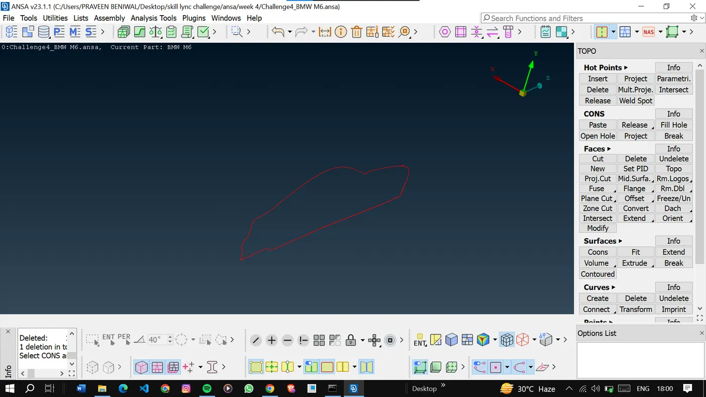
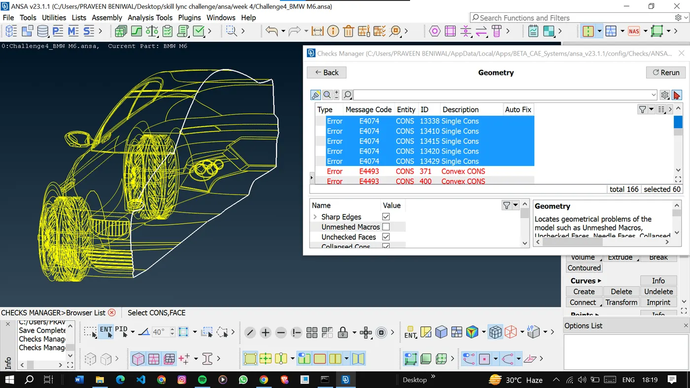
Finally done with the geometry cleanup and go to the next step which is PID creation and assignment.
<!-- [if !supportLists]-->2. <!--[endif]-->PID Assignment and Surface Meshing: Surface meshing is the process of dividing the surfaces of the geometry into smaller elements to prepare for volume meshing. The following target lengths were assigned to specific components:
<!-- [if !supportLists]-->· <!--[endif]-->Body - 3 mm
<!-- [if !supportLists]-->· <!--[endif]-->Lights - 4 mm
<!-- [if !supportLists]-->· <!--[endif]-->Grills - 1 mm
<!-- [if !supportLists]-->· <!--[endif]-->Rims and Tyres - 2 mm
<!-- [if !supportLists]-->· <!--[endif]-->Optical Rear view mirror - 2 mm
<!-- [if !supportLists]-->· <!--[endif]-->Window - 2 mm
<!-- [if !supportLists]-->· <!--[endif]-->Silencer - 3 mm
<!-- [if !supportLists]-->· <!--[endif]-->Logo - 1 mm
<!-- [if gte vml 1]>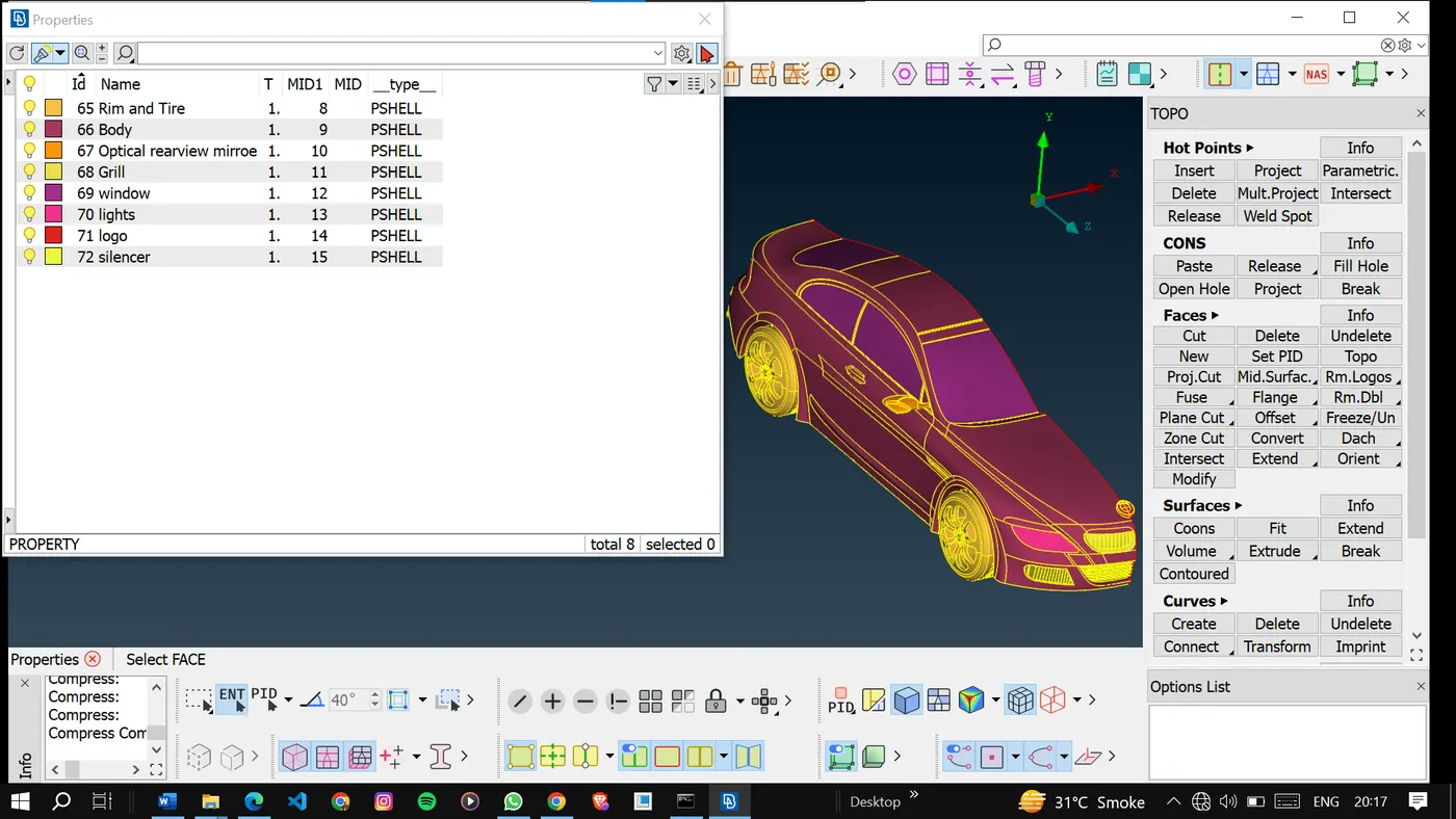
After the PID assignment, we can for meshing.
3. surface meshing process: Surface meshing was conducted using an algorithm that divides each component's surface into smaller elements according to the specified target lengths. This process ensures that the mesh captures the intricacies of the geometry while maintaining the desired element size. It provides a foundation for subsequent volume mesh generation.
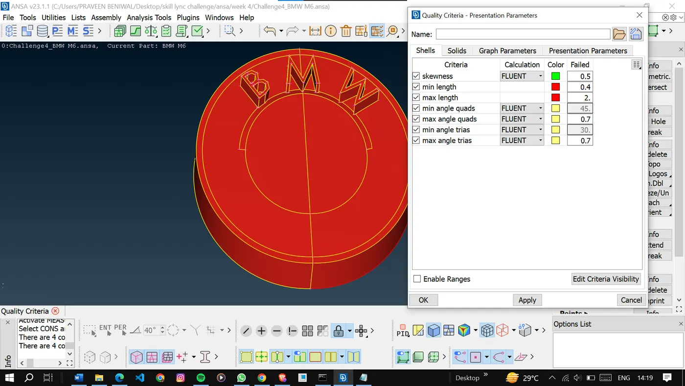
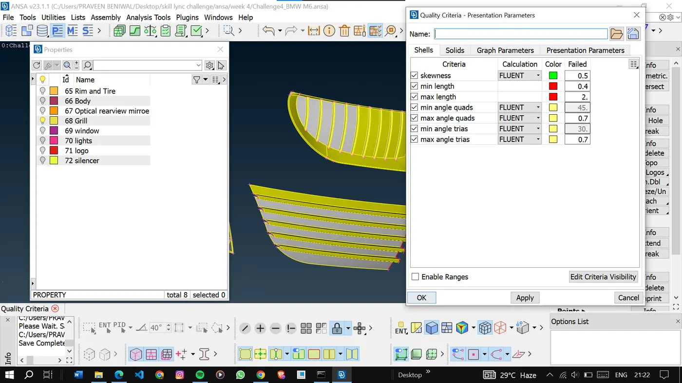
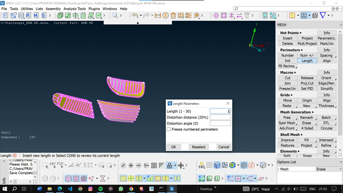
So to mesh the model we have to provide the mesh parameters and quality criteria for meshing.
<!-- [if gte vml 1]>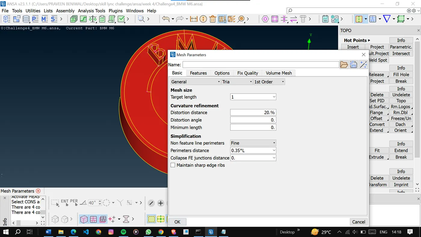
Enter the given mesh length.
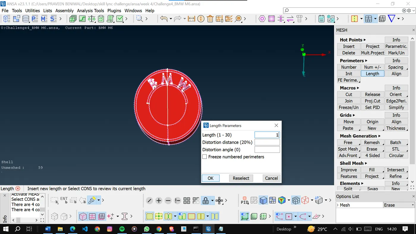
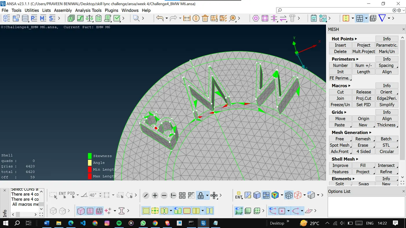
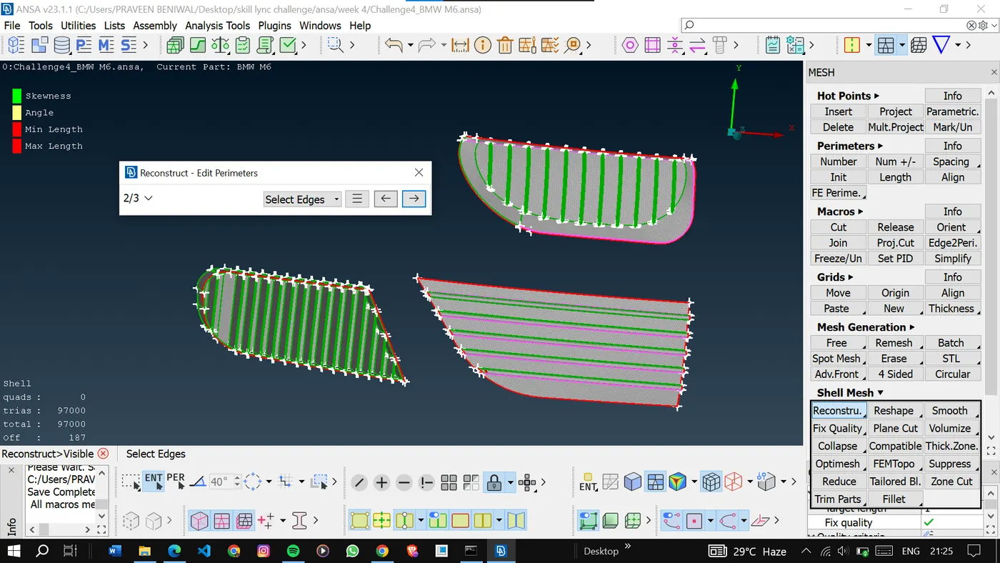
To solve the off elements we can reconstruct the the mesh.
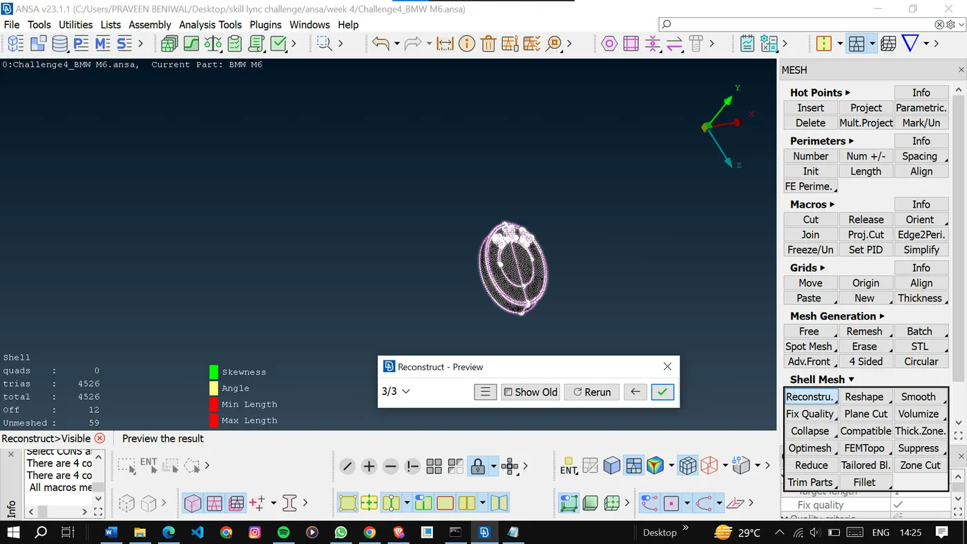
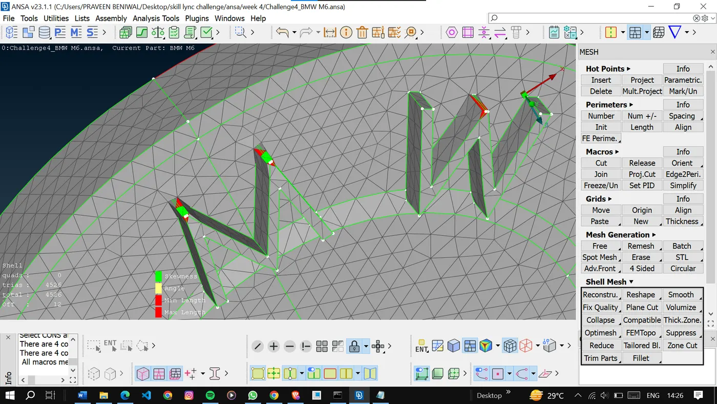
And also perform some topological cleanup if required.
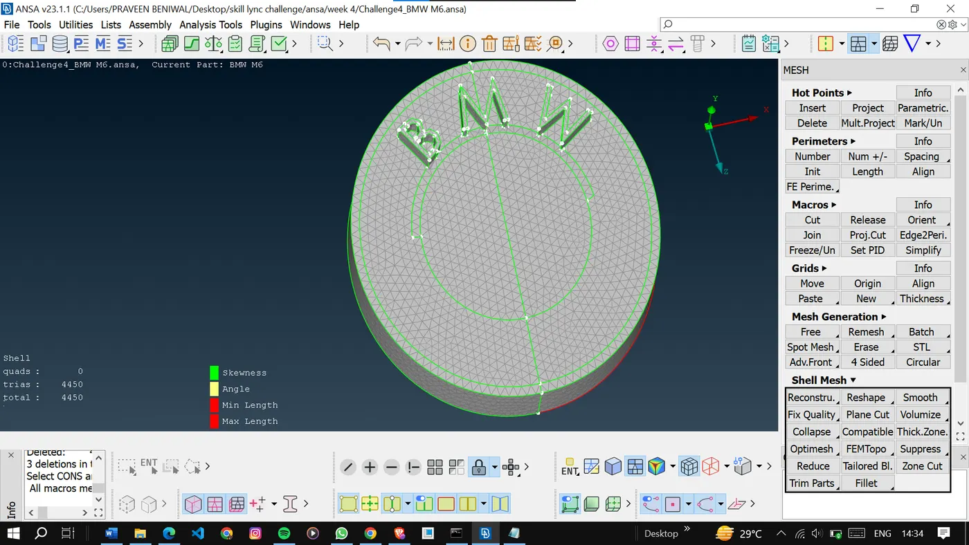
Now assign the values to the quality criteria, target length, and the mesh parameters by confirming the smallest length present in the grill area.
<!-- [if gte vml 1]>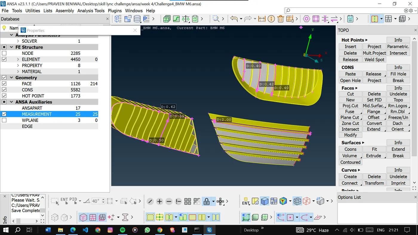
Here also we can do the same to solve the off elements so we can reconstruct the mesh.
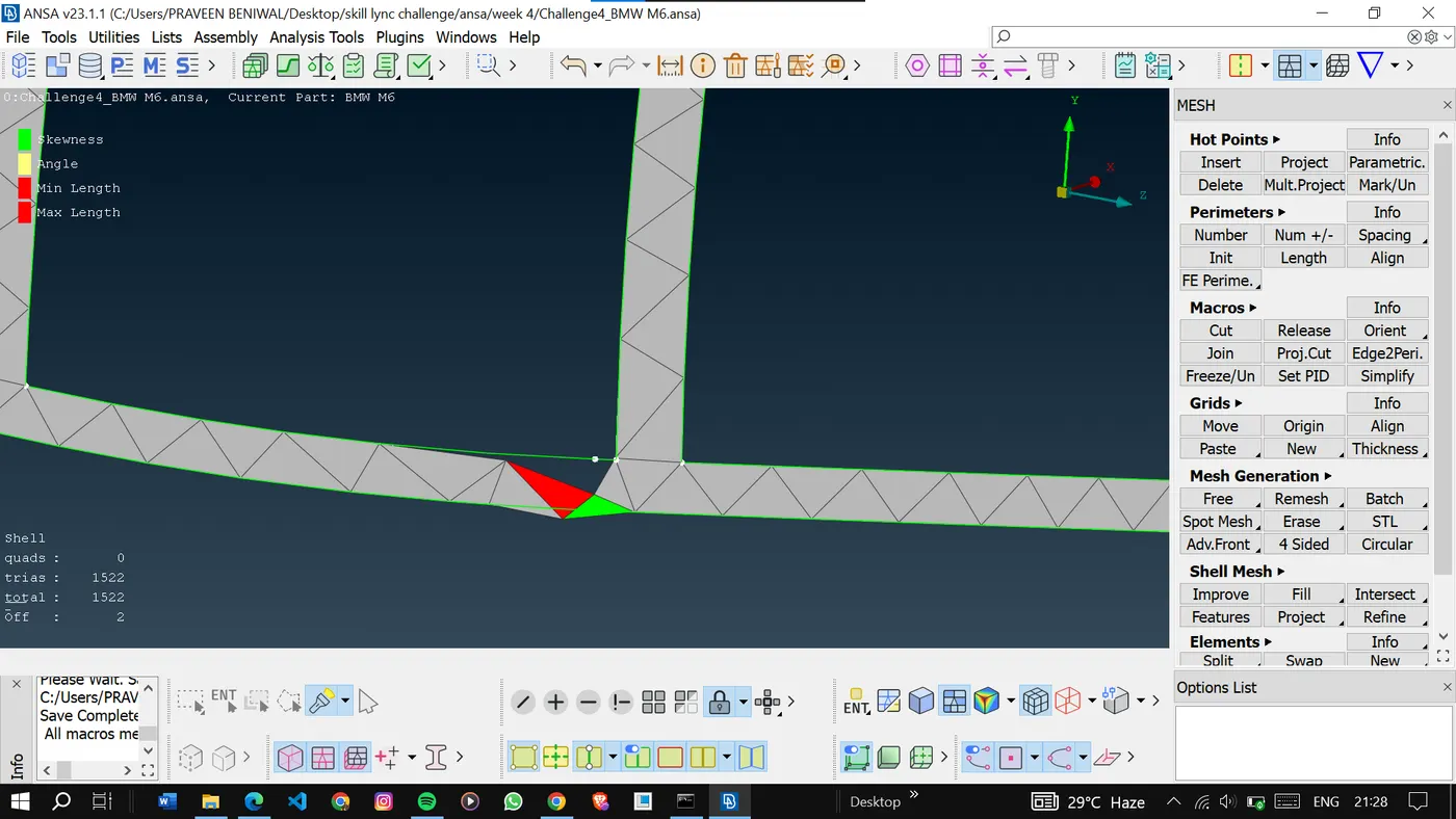
Now the element can be corrected using the move option in grids.
Now there are no off elements in this PID.
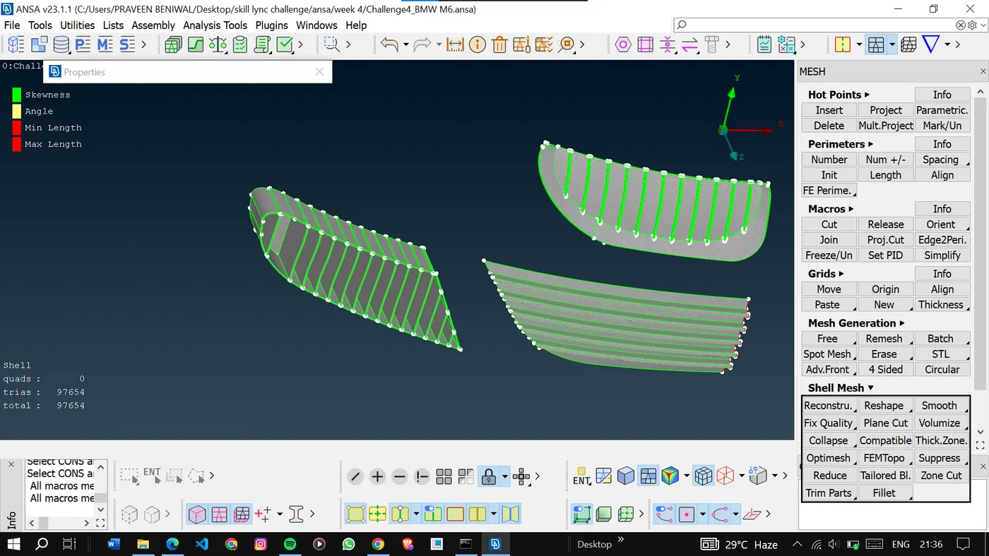
Similarly, mesh other pids also.
Here are the final results of other pids.
<!-- [if gte vml 1]>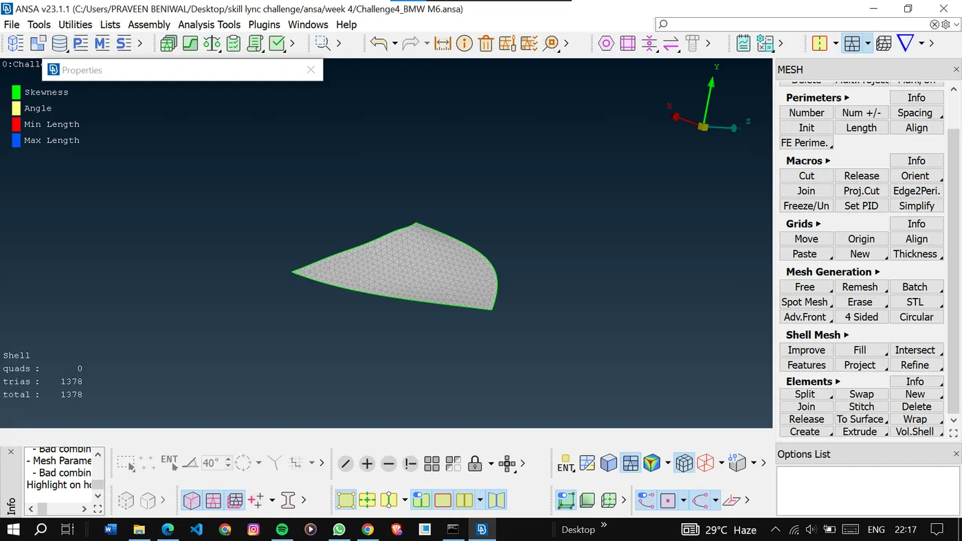
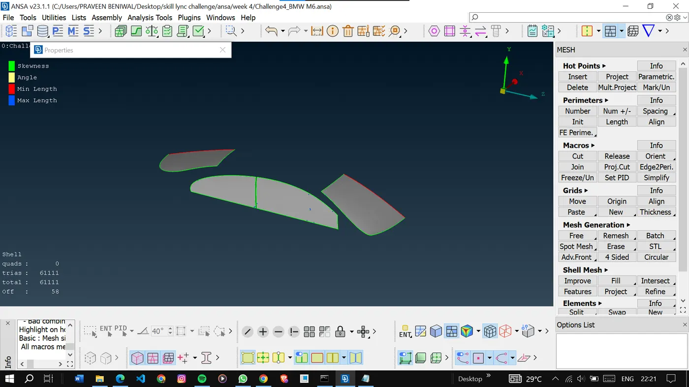
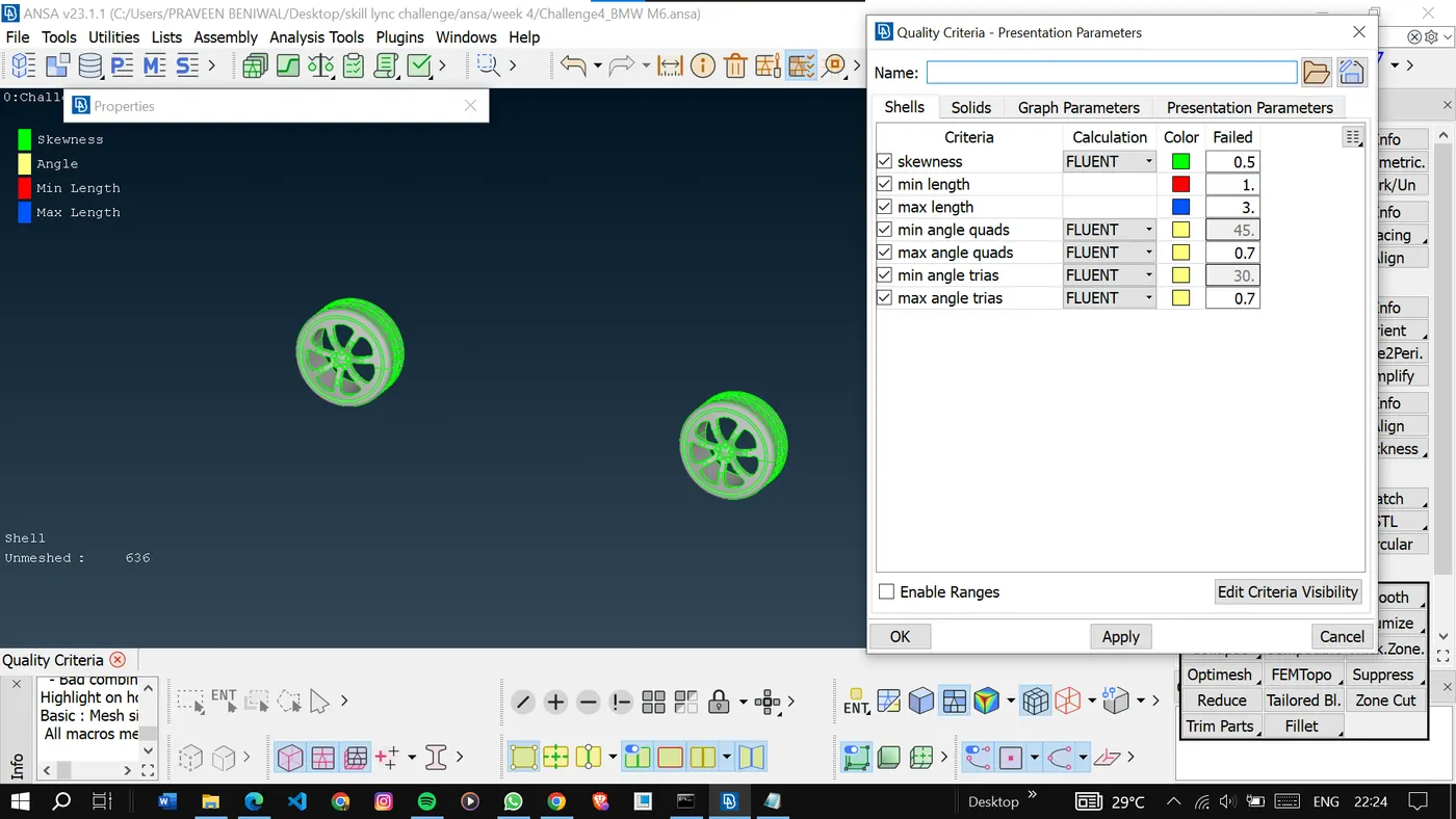
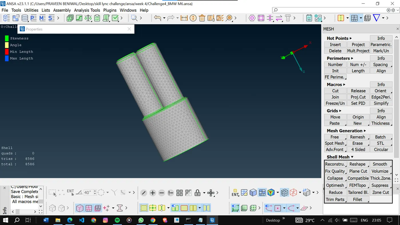
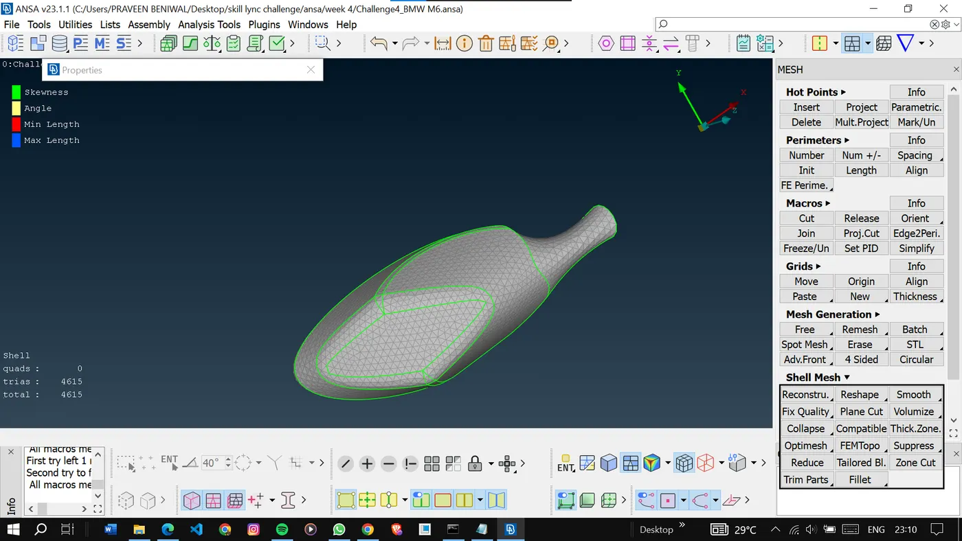
Finally, we are left with only the body pid this part is more critical than others because it shares the cons with other pids so we to be careful while meshing this because it can erase the mesh on other pids.
<!-- [if gte vml 1]>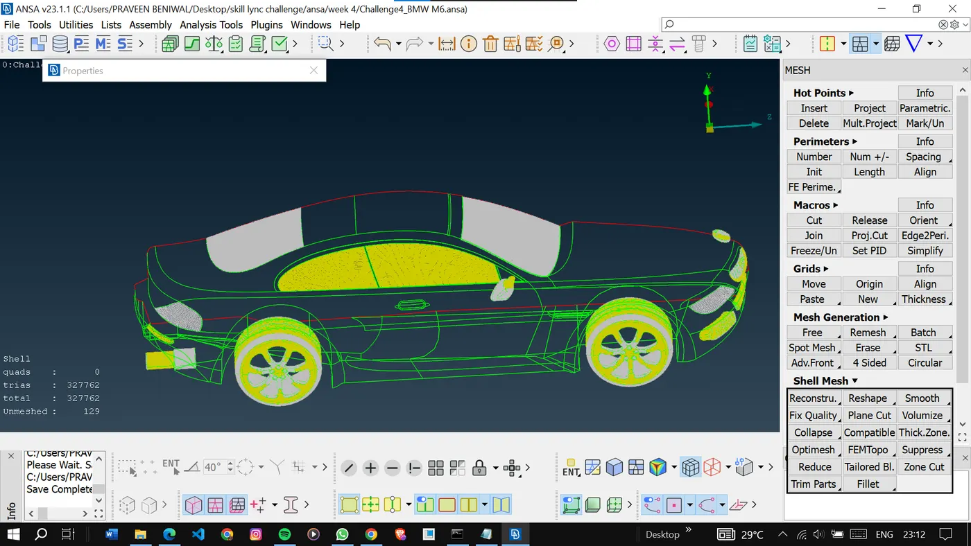
Give the quality criteria and mesh parameters.
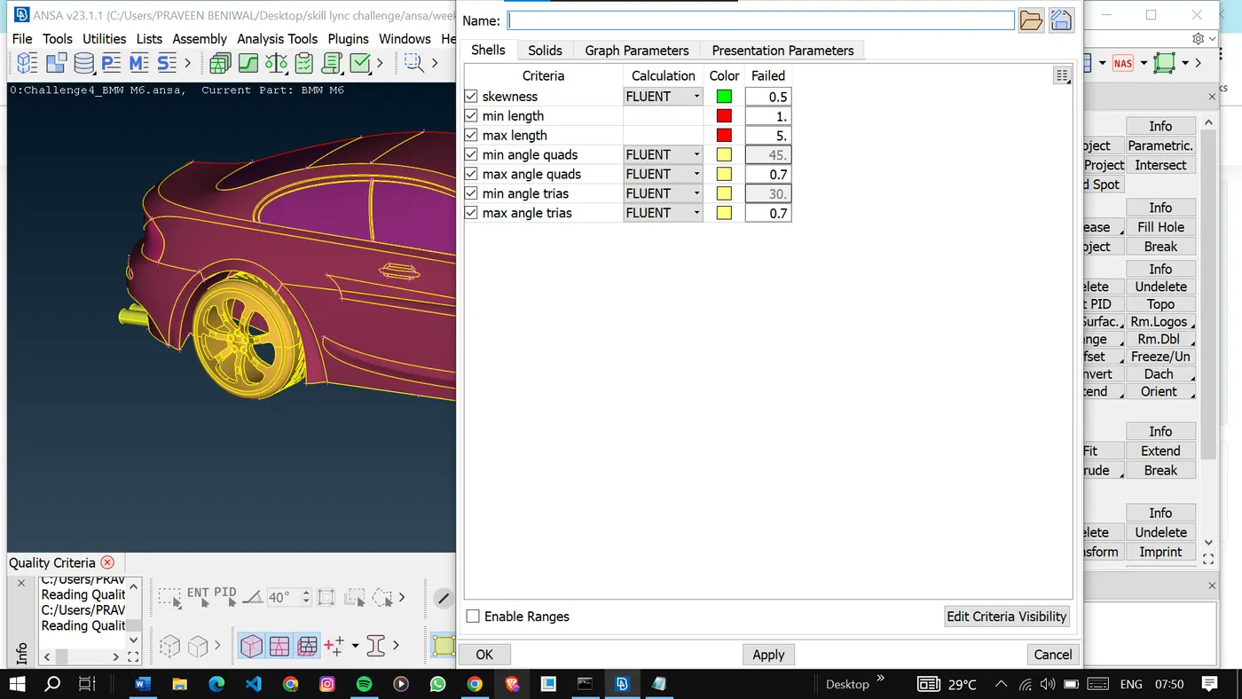
This time we only five the perimeter values, not the macro to achieve the proper mesh. and also deselect the cons that are shared by other bids.
<!-- [if gte vml 1]>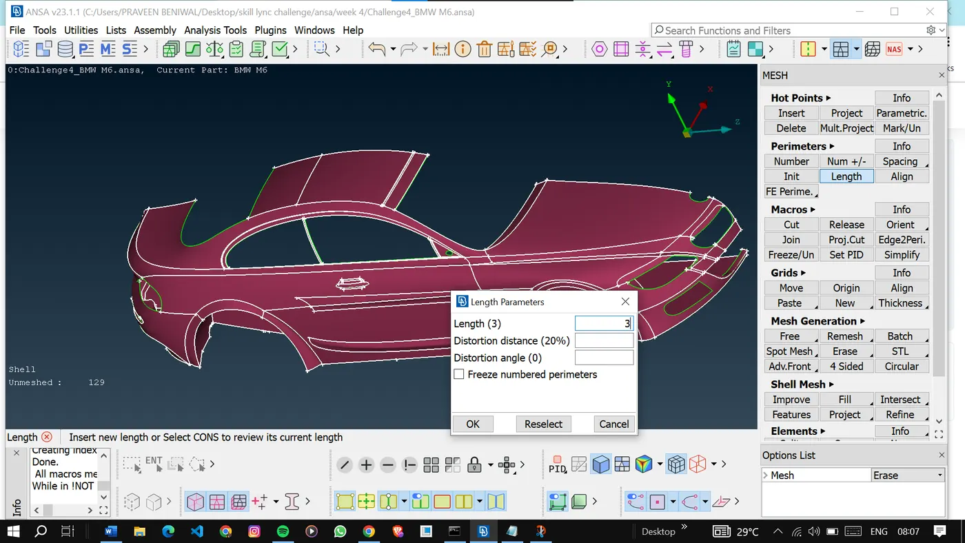
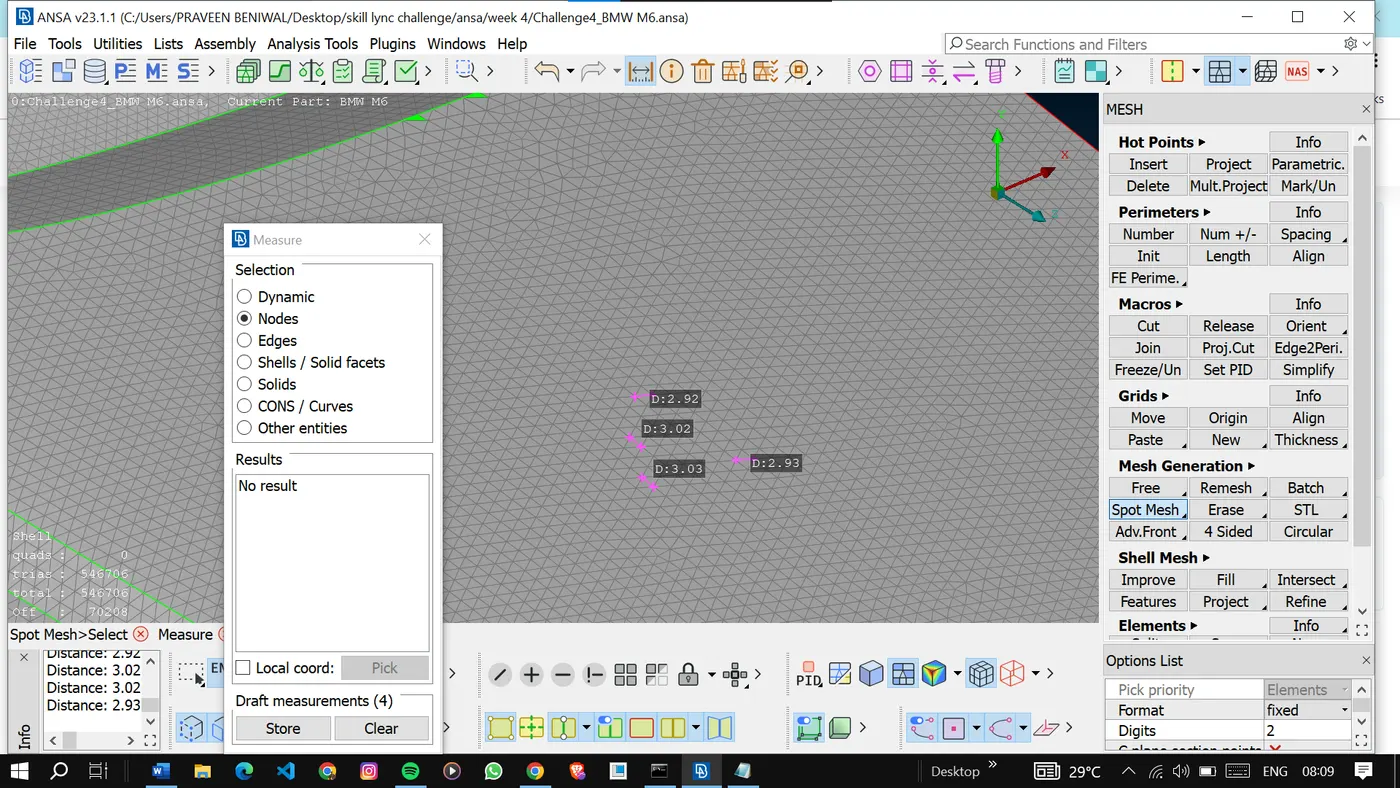
Mesh is good but there are so many elements present here, try to reconstruct the mesh to reduce the off elements.
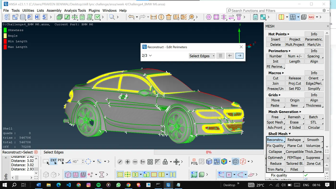
Still so many off elements and it's showing an error in the minimun length criteria.
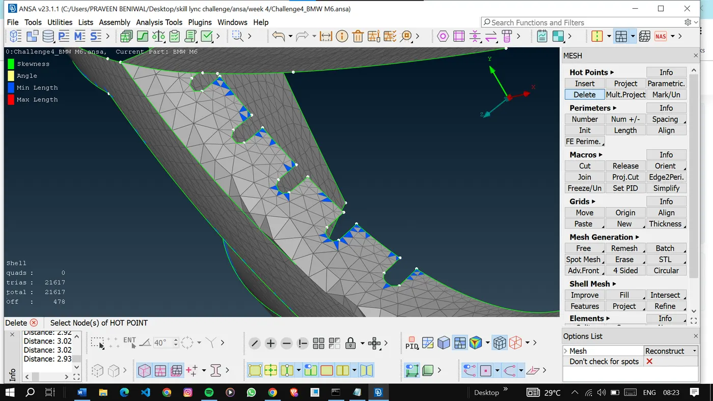
To correct the mesh we need to give a lesser min length that is 0.6.
<!-- [if gte vml 1]>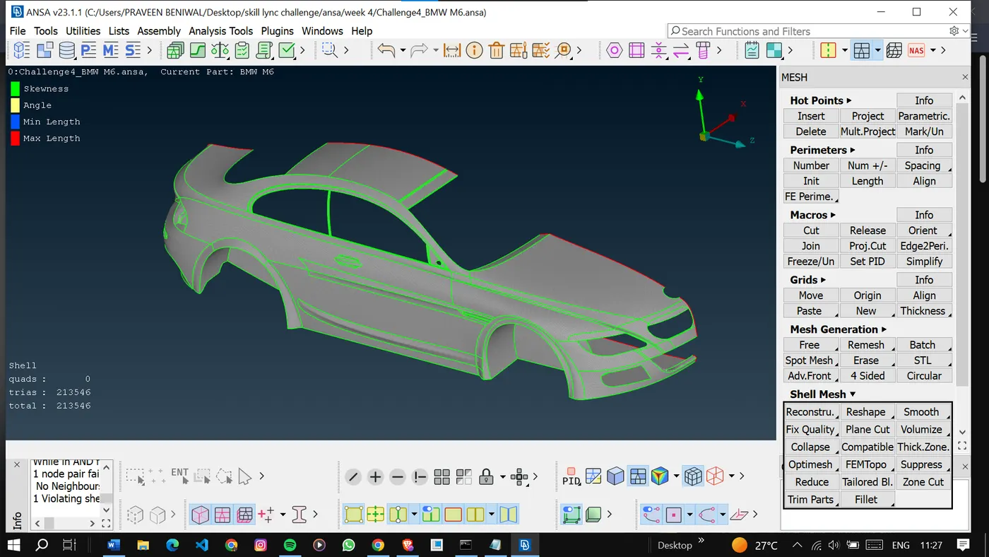
After correction, we can see there are no off elements present.
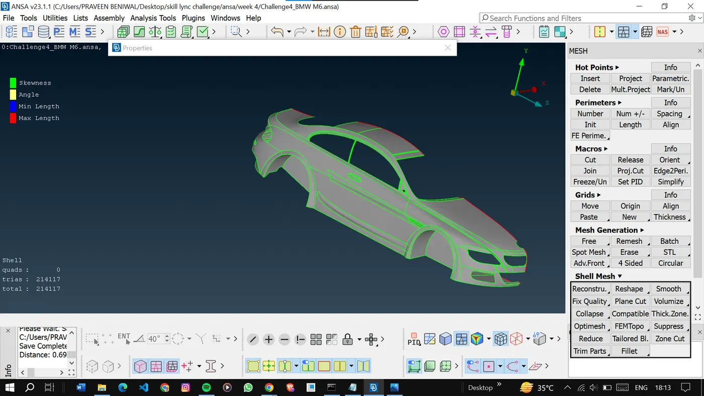
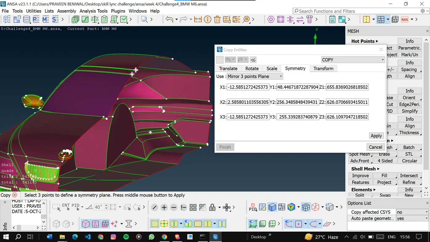
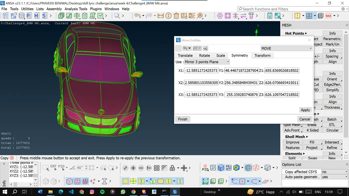
Now we will copy the model to the other side.
As we can see our full model with some errors.
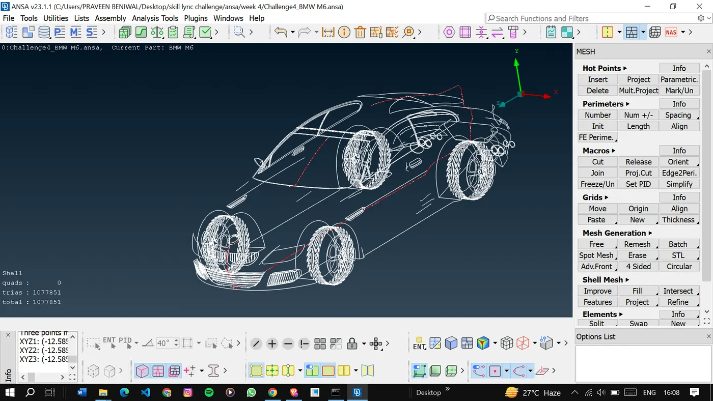
We will inspect the model in wireframe mode. And try to resolve the single cons.
Finally, go for geometry checks, and as we can see everything is fine.
<!-- [if gte vml 1]>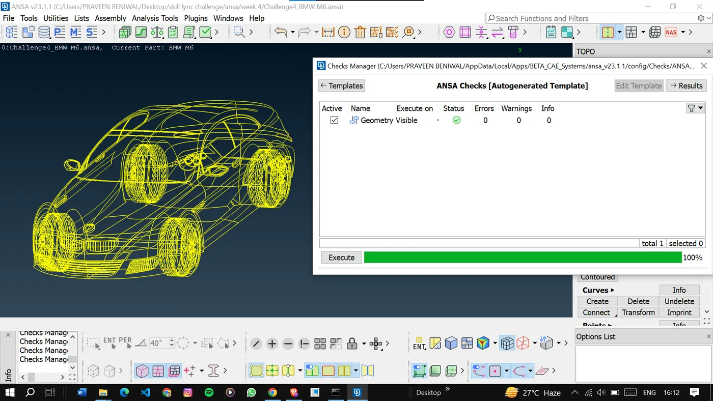
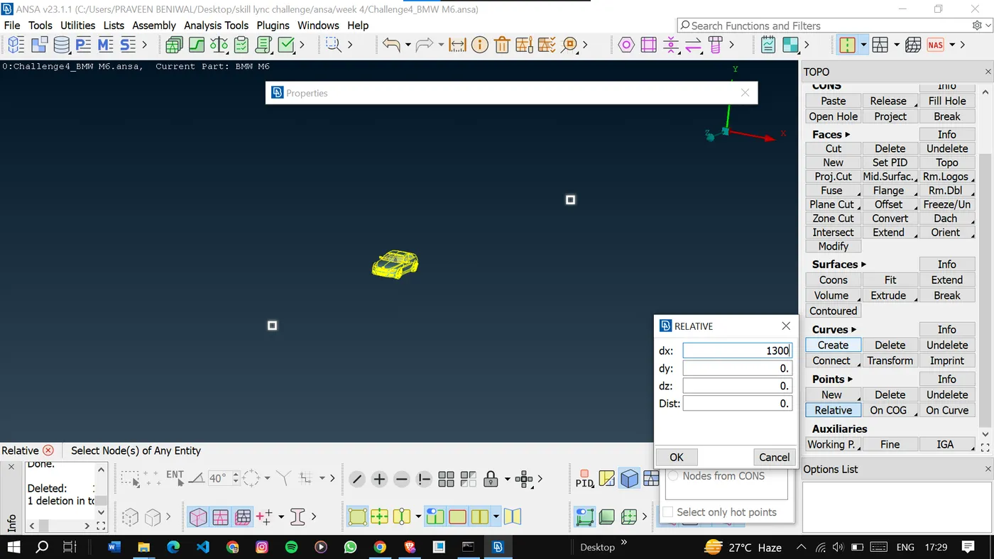
Now, it's time to make the wind tunnel by creating the points first then curves through the points.
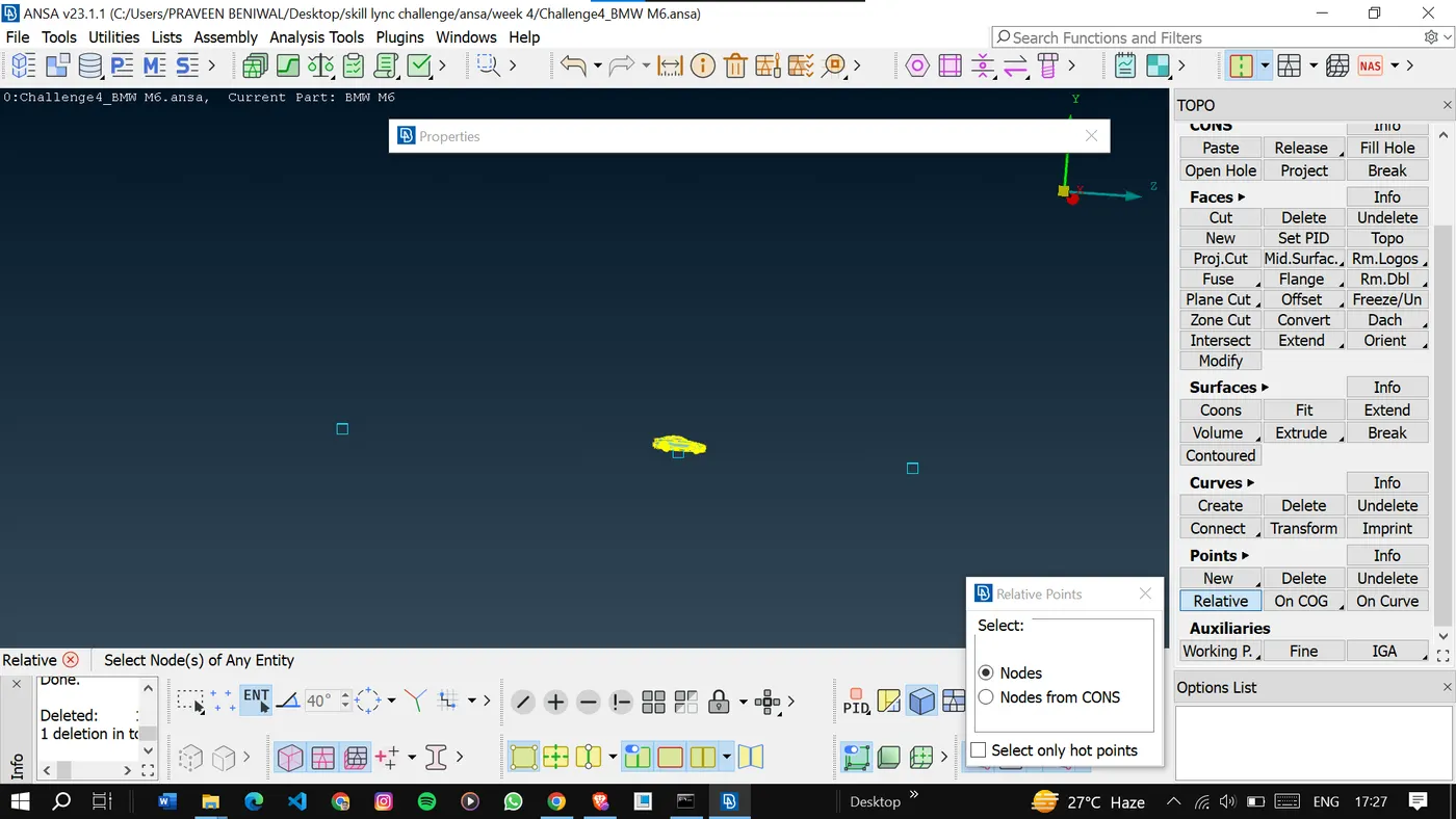
After creating the curves we can create a surface using the curves.
<!-- [if gte vml 1]>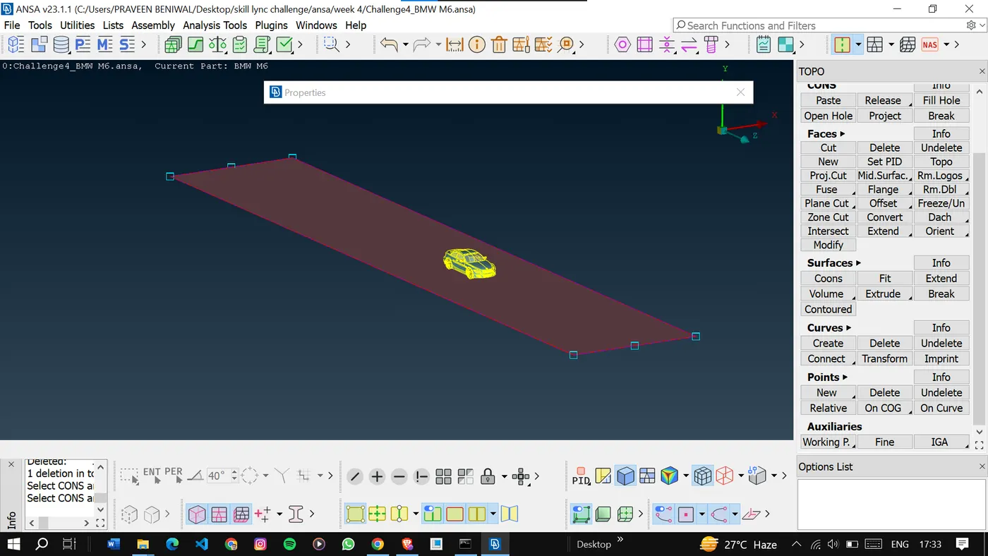
And by creating the surfaces we can make the wind tunnel.
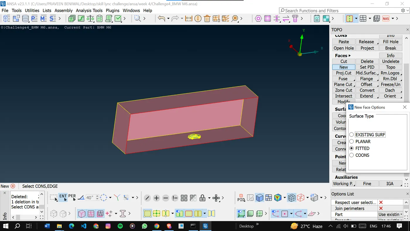
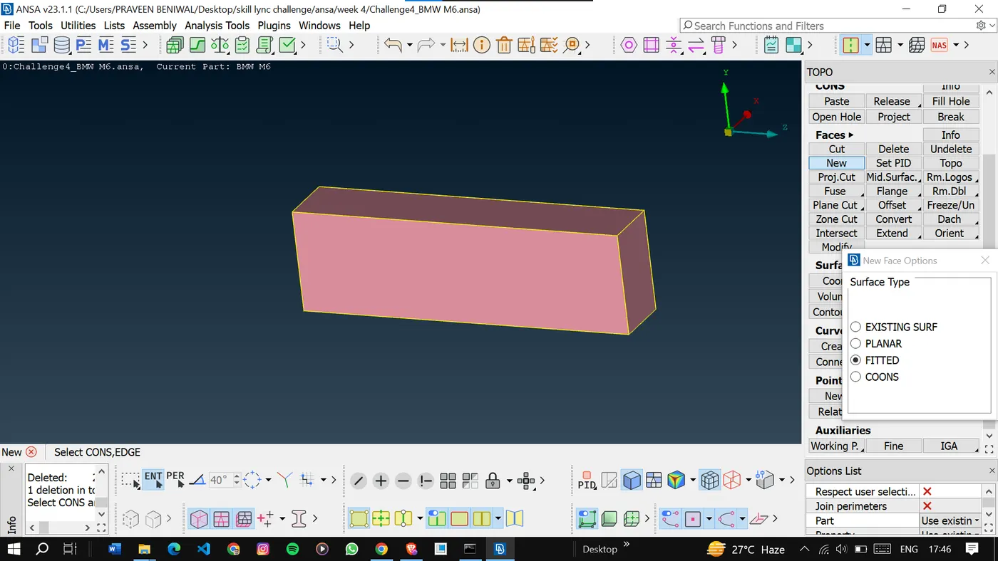
Once all the sides of the tunnel are made then assign the pids to the surfaces.
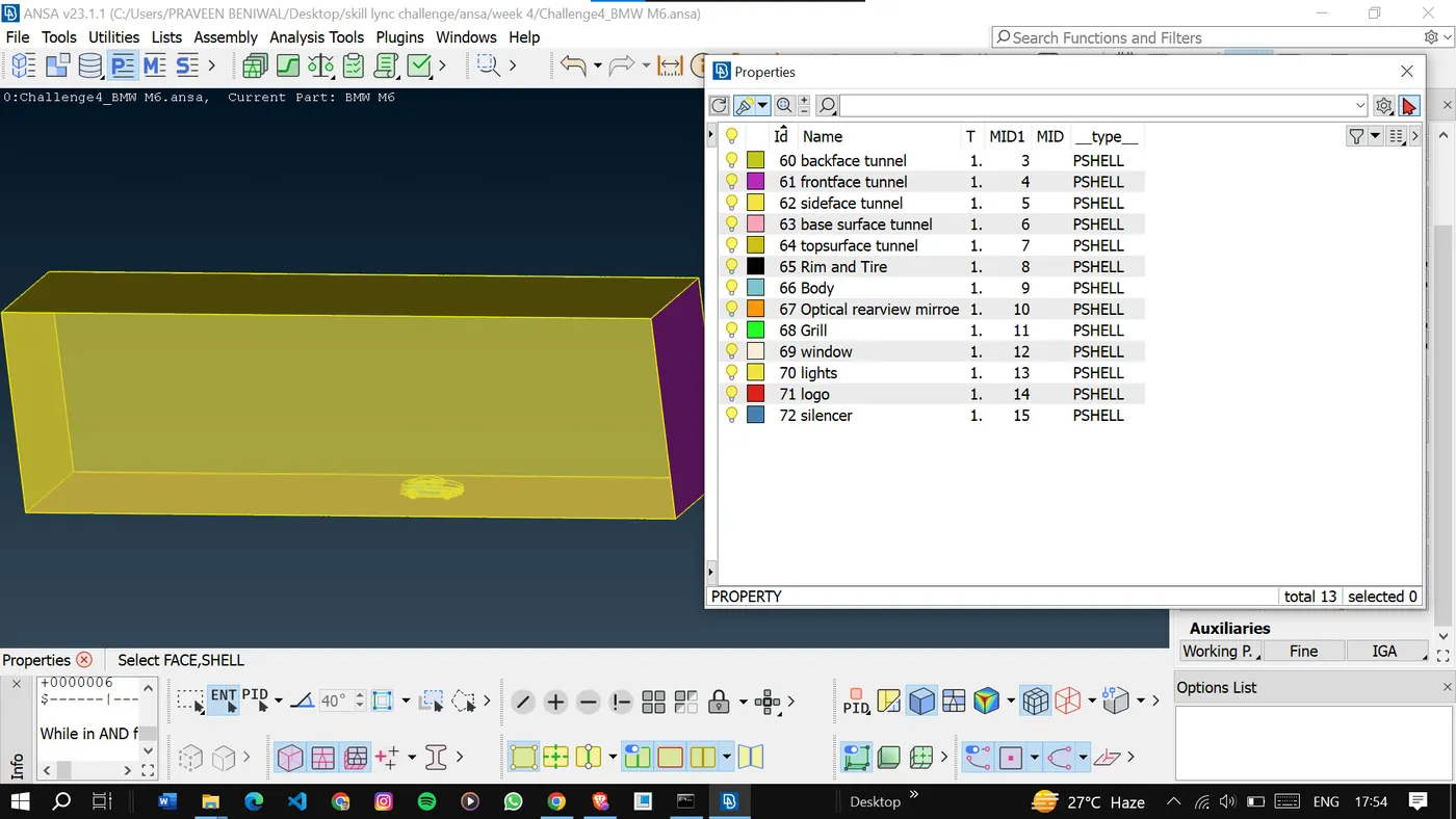
Once the pids are assigned then we can go for meshing the tunnel.
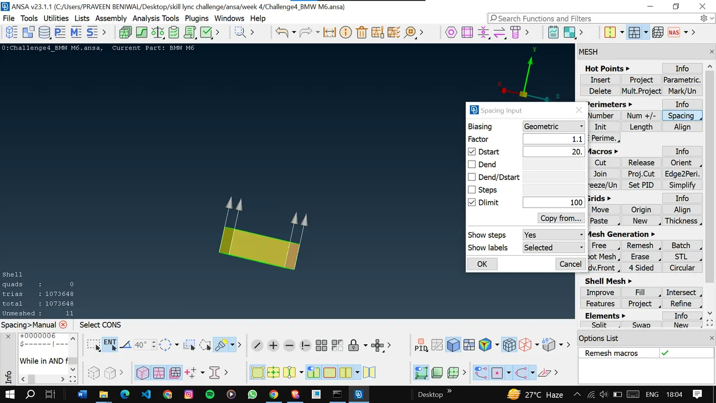
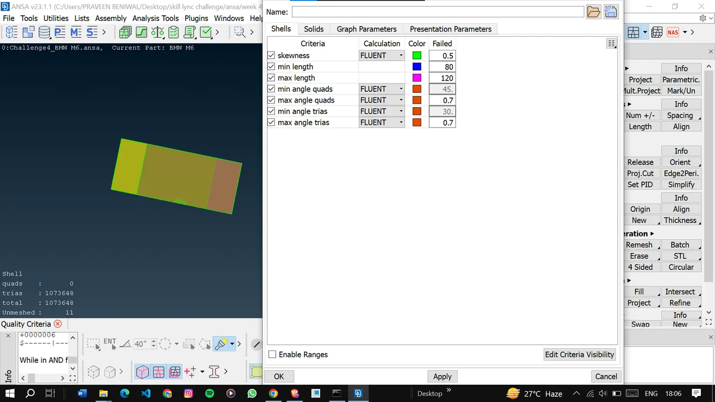
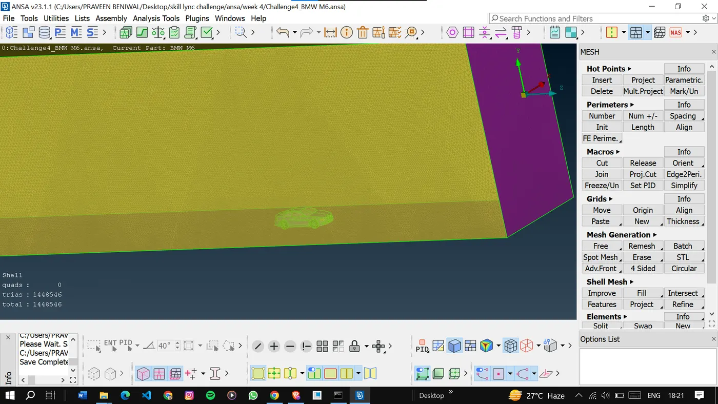
Once done with the surface meshing can go for the volumetric meshing for the first volume which is of interest and delete the rest volumes.
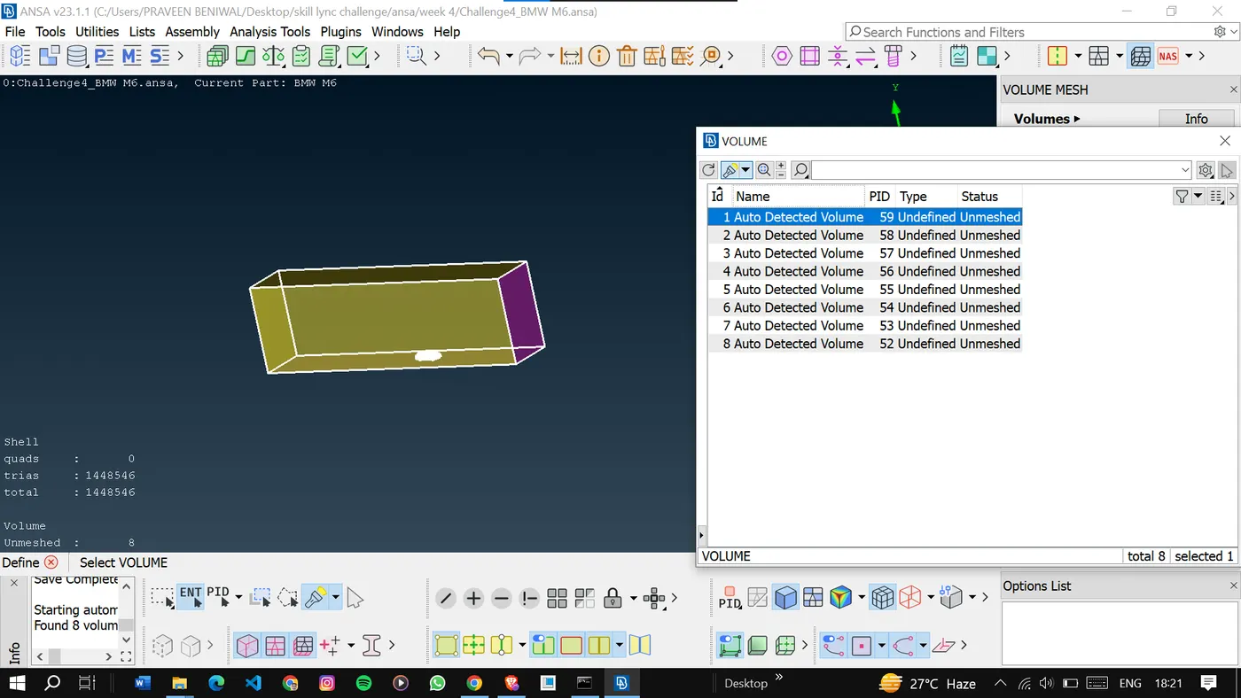
As the volumetric meshing of this volume can take so much time, we will not go for it.
Result:
Geometrical errors were rectified, and surface meshes were created, adhering to designated target lengths. And also the done the symmetry of the model to the other side. Subsequently, volumes were generated for each component, ensuring precision in meshing.
Conclusion:
In conclusion, this report has outlined the comprehensive process of correcting geometrical errors, generating surface and volume meshes, and assigning Process IDs for various components in the provided model. By adhering to the specified target lengths and utilizing advanced meshing techniques and the technique to copy the model to the other side, an accurate representation of the geometry has been achieved. This clean and well-defined mesh will serve as a foundation for subsequent simulations and analyses, contributing to accurate and reliable results.