Project 1 : CFD Meshing for Tesla Cyber Truck
QUESTION:
For the given model, check and solve all geometrical errors and Assign appropriate PIDs. Perform meshing with the suitable Target length and element Quality criteria.
Target lengths for the different parts of a model can be decided by your own. The finer mesh will give good results and will compromise with the longer processing time.
(Note: Kindly take reference of Week 4 videos for other common Quality criteria)
Meshing Wind tunnel volume with tetra elements may take up to 2 days of time. So that is not compulsory to perform. As this is a major project, It is advisable to mesh that completely by taking some days of time. Write a detailed report for the same.
Note: All the 2D elements(Trias) in your model should clear the quality criteria (i.e. Off elements should be zero). Depending upon this you will be awarded marks.
ANSWER:
model link:
https://drive.google.com/file/d/1XAiIOQ-bSDJRj9sROmWRt0k1SBjK710x/view?usp=drive_link
Aim:
The aim of this report is to create a suitable mesh for the given model, addressing any geometrical errors and assigning appropriate Property IDs (PIDs). The mesh will be generated with the goal of balancing mesh quality and processing time.
Procedure Steps:
1. Geometry Check and Correction: The first step in the meshing process involves identifying and rectifying geometrical errors present in the given model.
Open the model in the ANSA pre-processor.
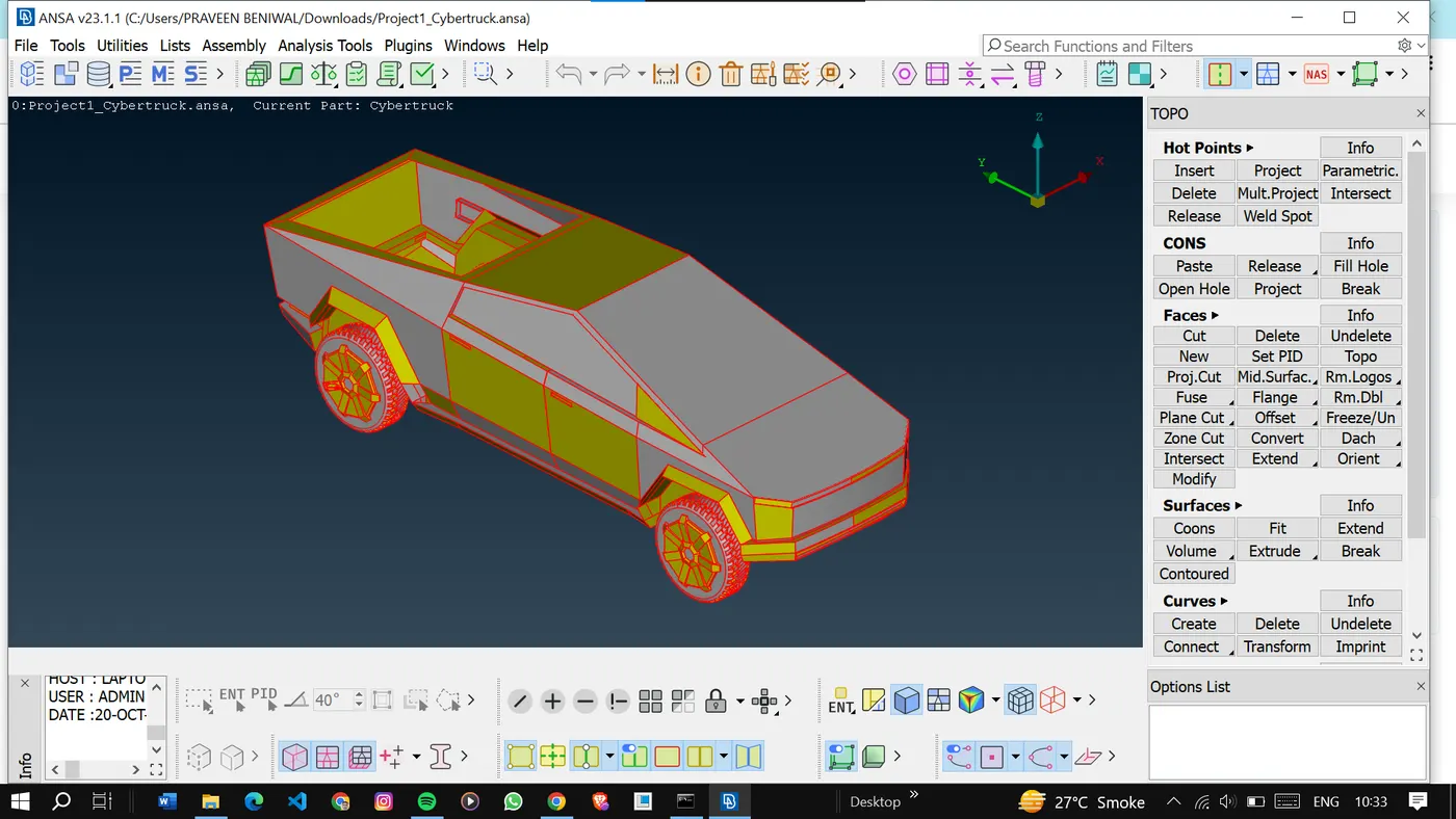
Inspect the geometry for errors, including gaps, overlaps, intersections, and other issues.
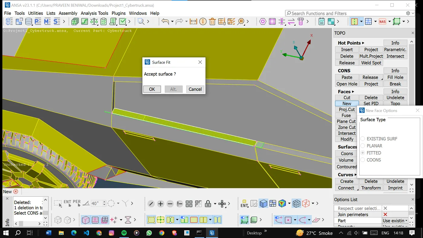
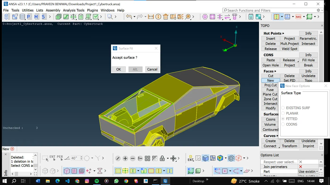
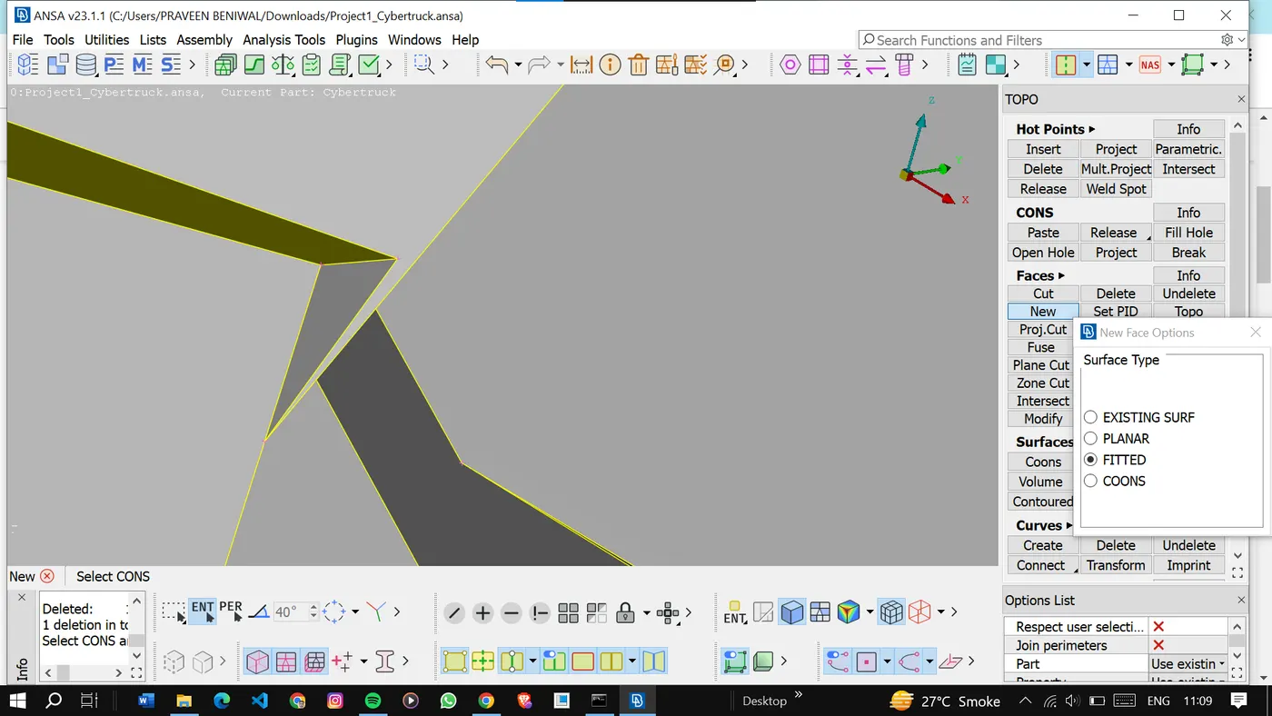
Patch the surface by creating new surfaces.
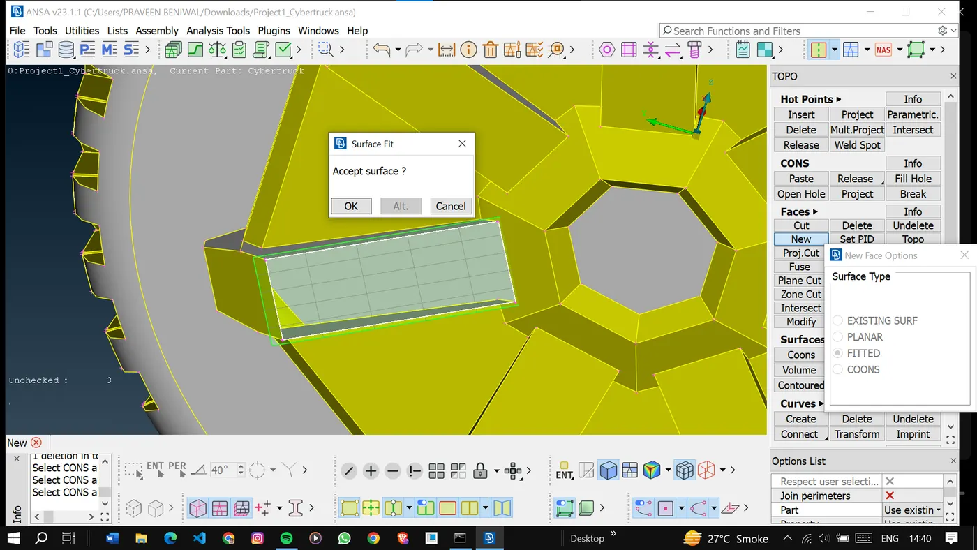
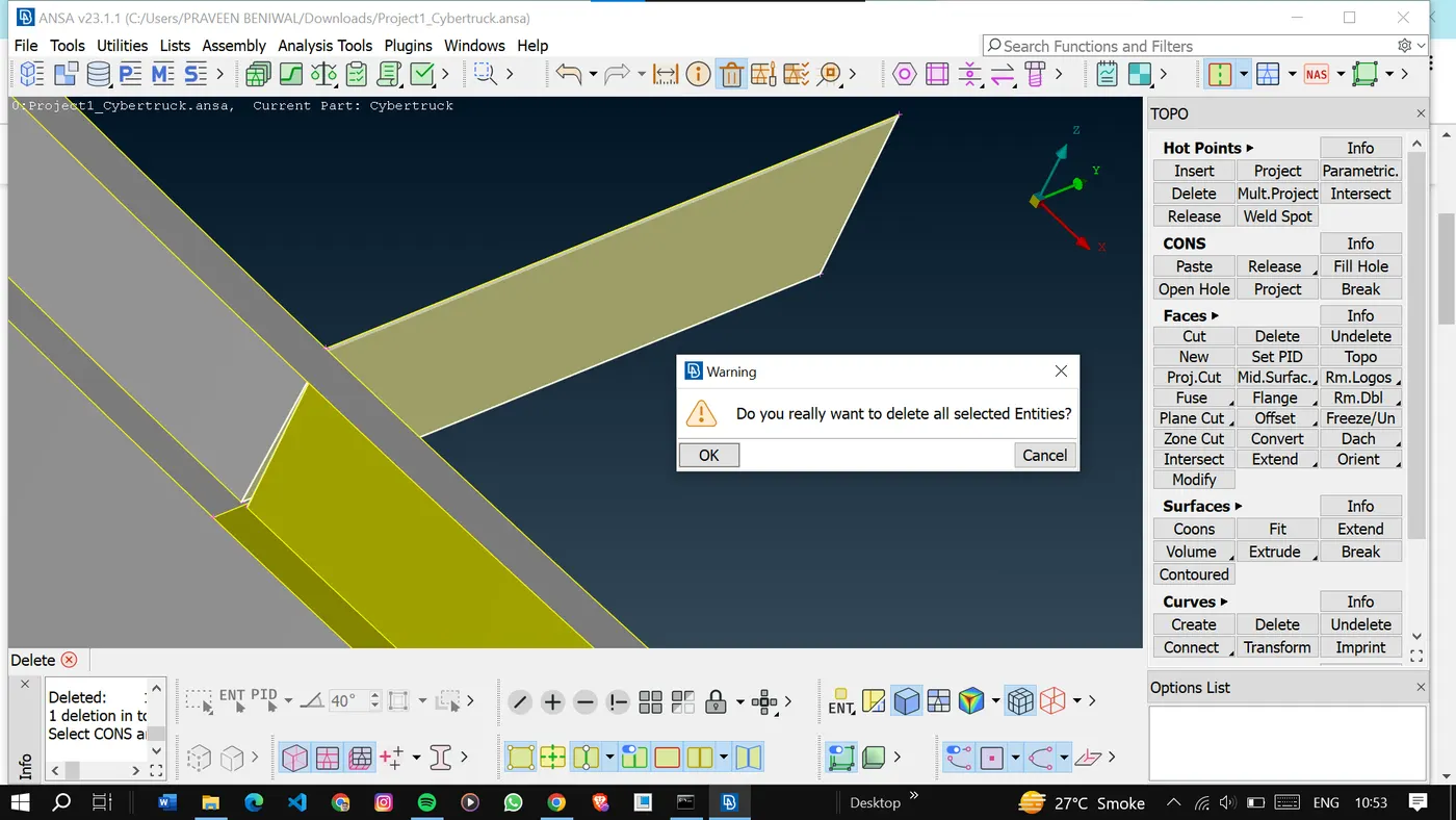
Also, remove the unwanted and very small surfaces.
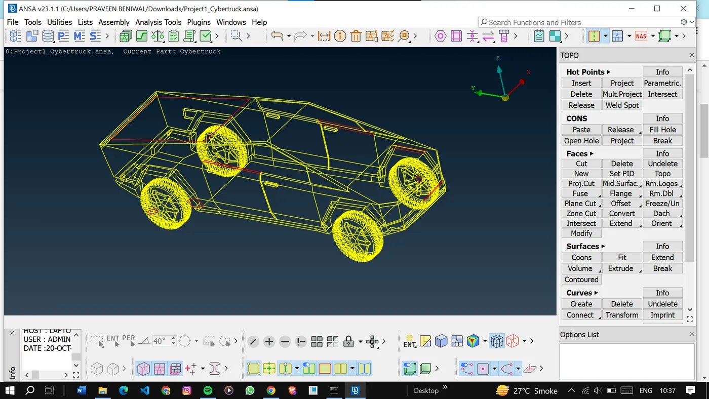
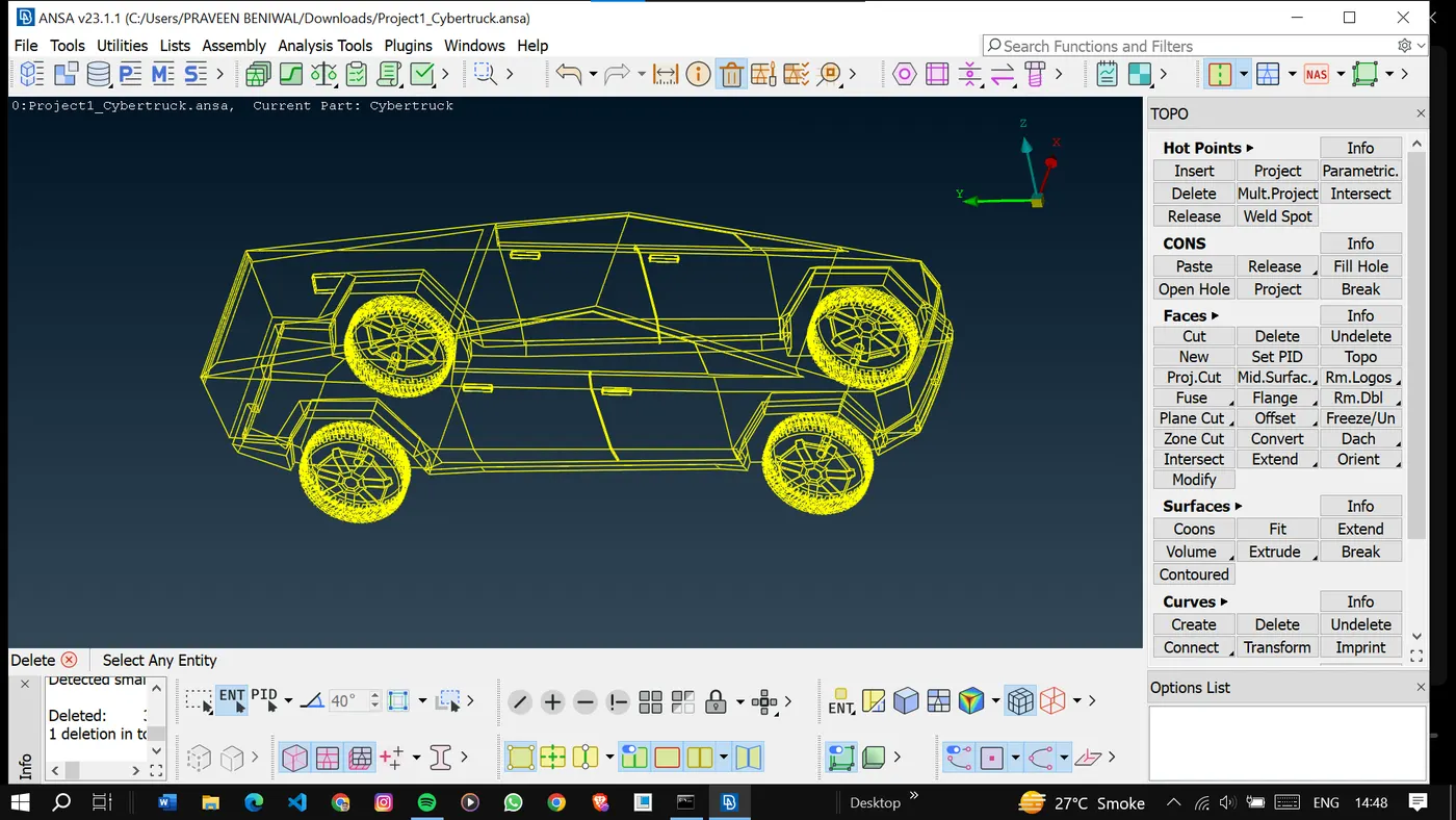
After correcting the geometrical errors we will examine the model in wireframe mode.
And finally go for the geometry checks.
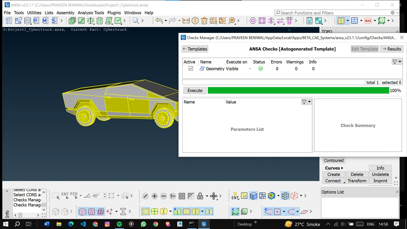
Once done with the geometry cleanup go to the next step which is PID creation and assignment.
2. PID Assignment:
Now we will Identify the different parts or materials in the model.
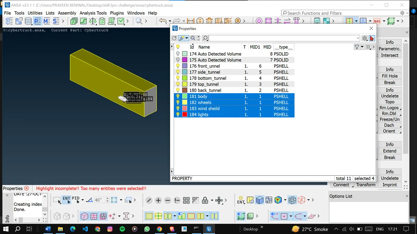
Assign the appropriate Property IDs (PIDs) to each part or material. PIDs are numerical labels that define the material properties and boundary conditions for each region of the model.
After the PID assignment, we can go for meshing.
3. Mesh Generation:
Decided the target length for the mesh element size of each part of the model. Keeping in mind that Finer meshes will provide more accurate results but may increase processing time.
Before deciding the target length we will measure the smallest lengths present in the PIDs.
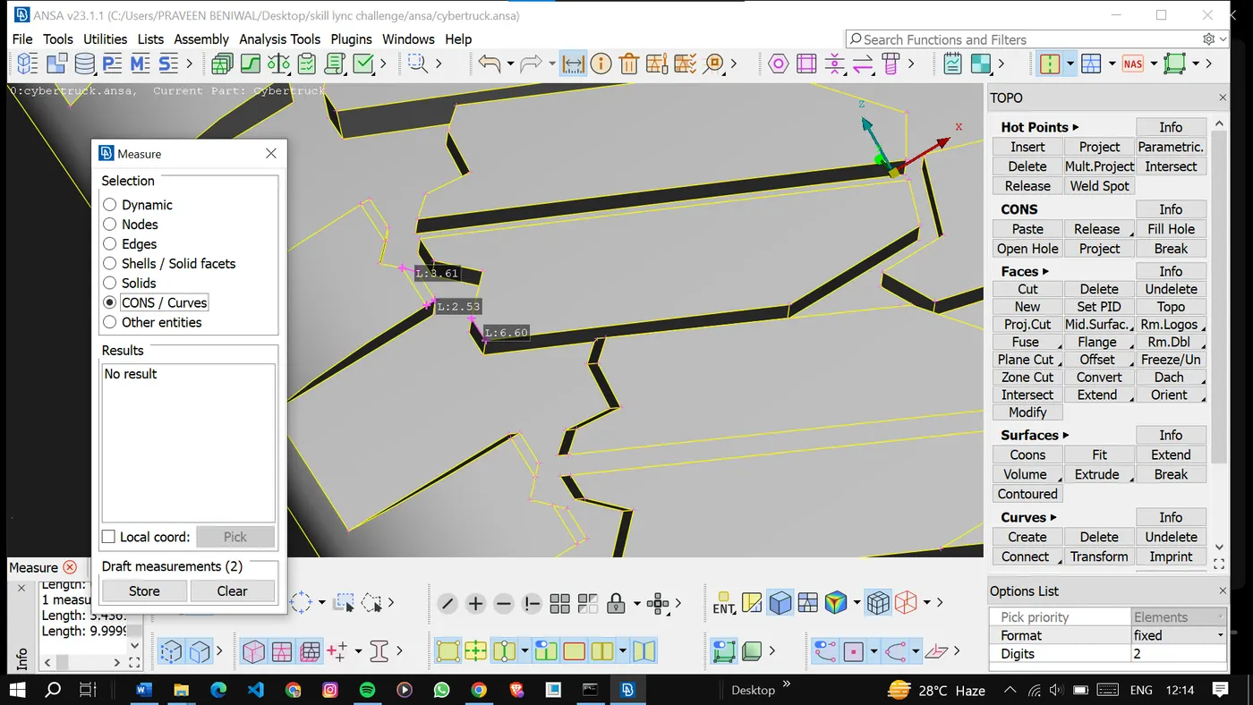
Consideration of the smallest part is very important so that no surface is left without meshing.
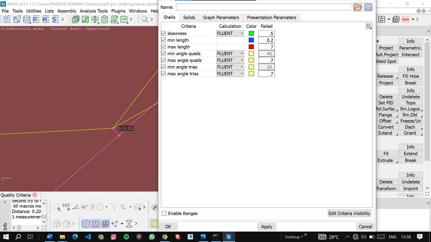
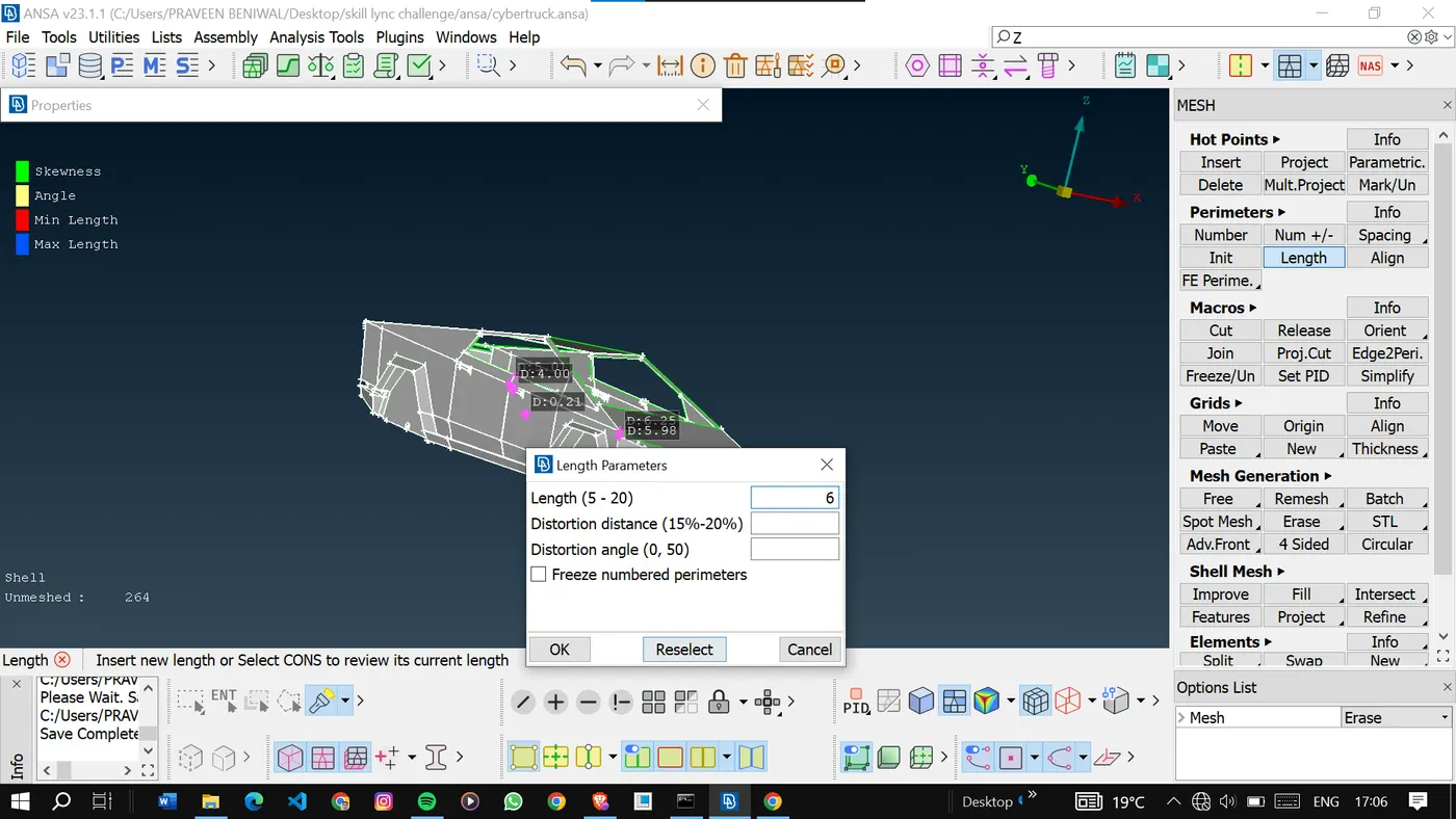
For this PID the decided target length is 5 because if the target length is smaller than 5 it will produce so many elements and a greater target length may not give good results.
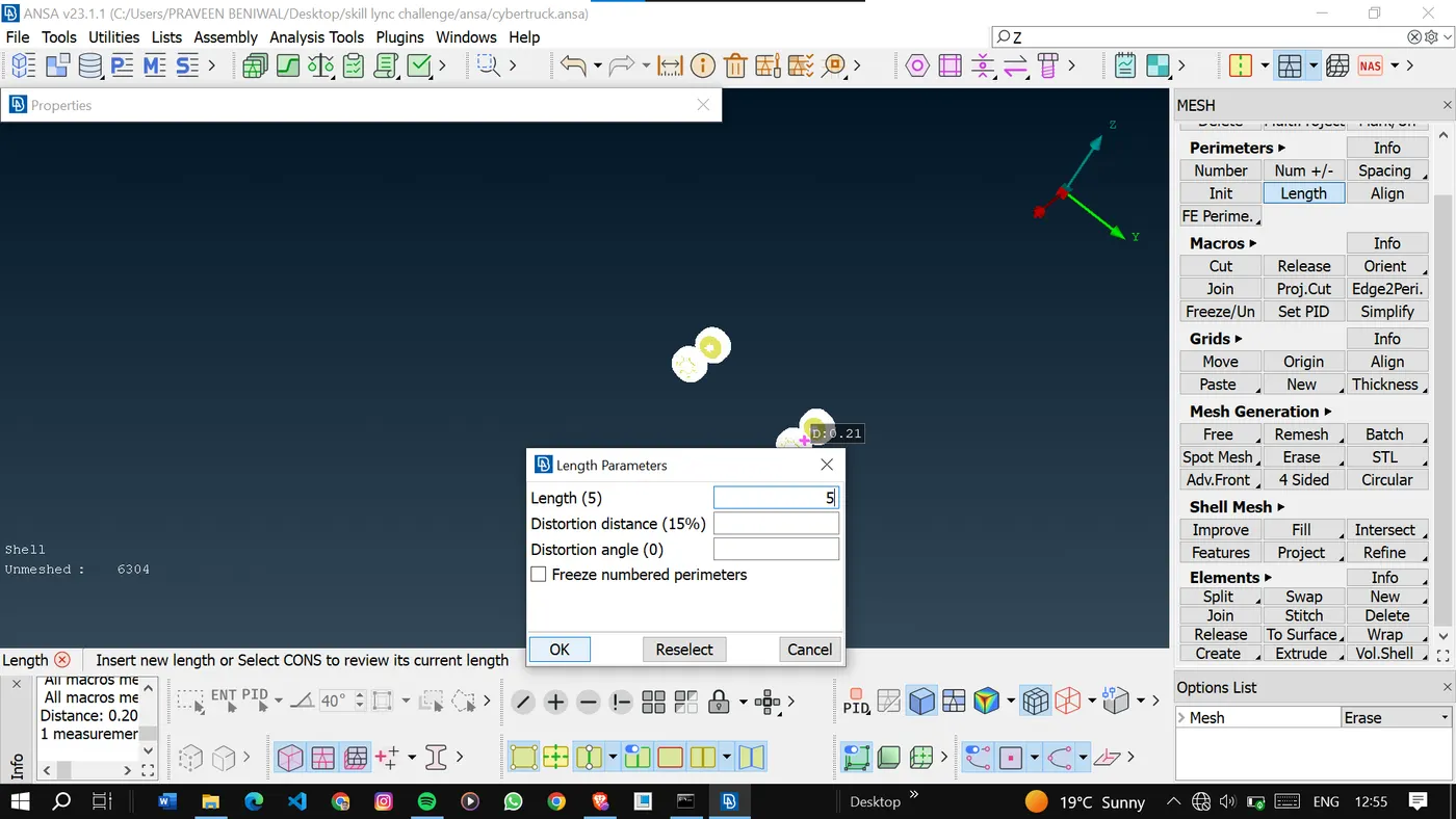
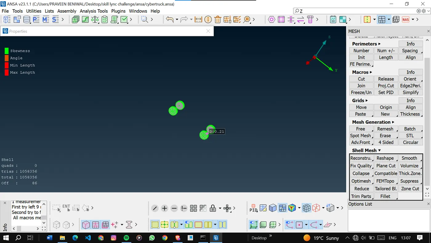
As we can see some off elements are present so we will try to resolve them.
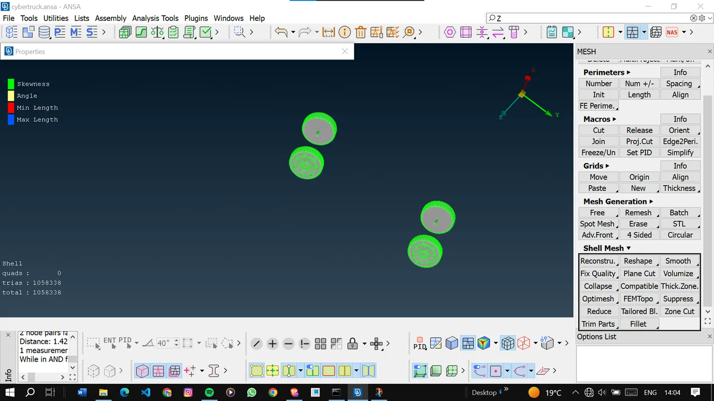
Similarly, we will decide the target length for other PIDs and mesh them.
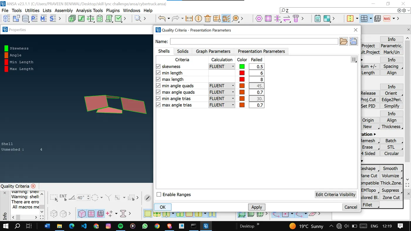
As the wind shield is a very simple surface we don’t want so many elements. so the target length can be 7mm.
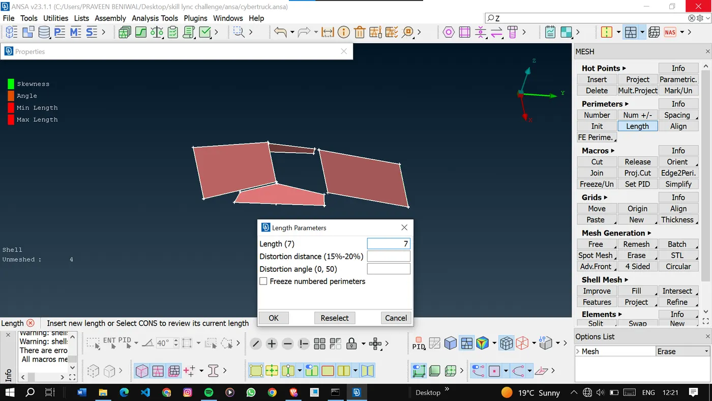
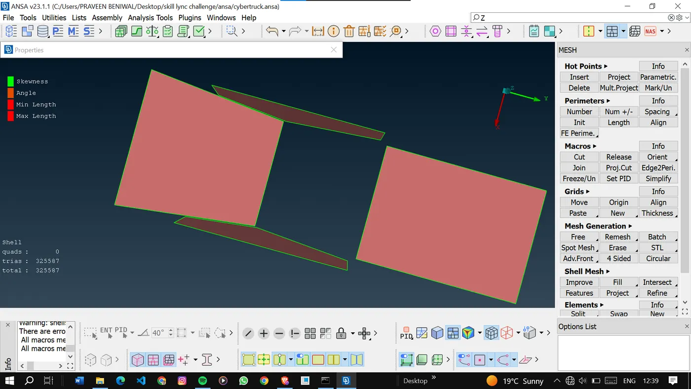
Similarly, we will mesh the lights and body.
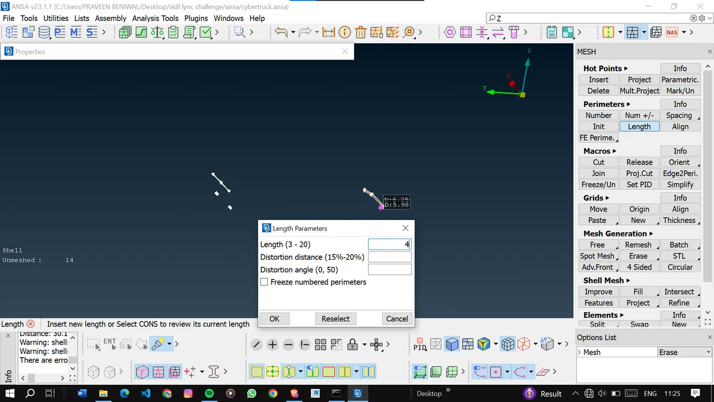
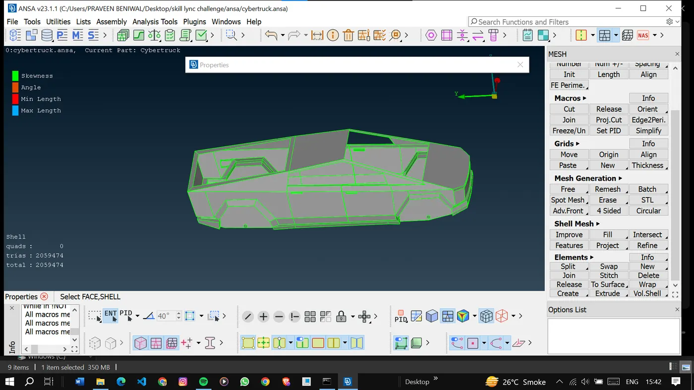
Once done with meshing.
We will go for Wind tunnel generation.
To generate the wind tunnel first of all we have to find the length of the car. Let it be x.
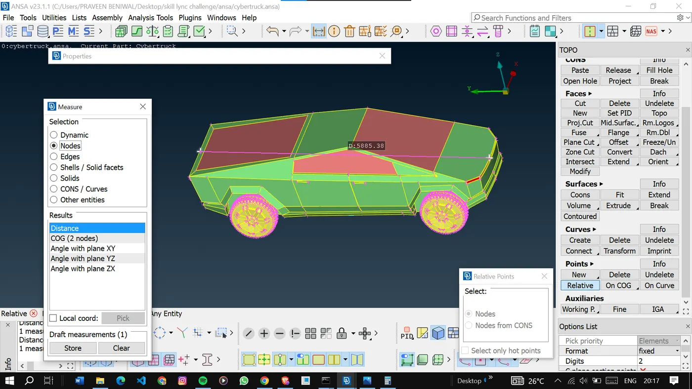
Now make the points to make the wind tunnel.
Here I have used the preferences for the points from the week 4 videos. That is 4x in front 3x in top and 7x in rear and x in sides.
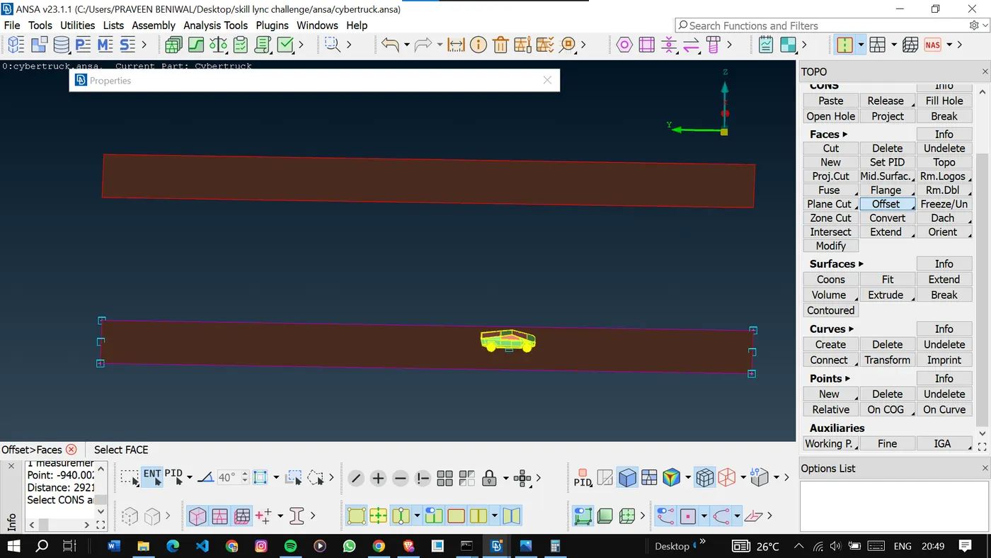
Delete the unnecessary points and the curves.
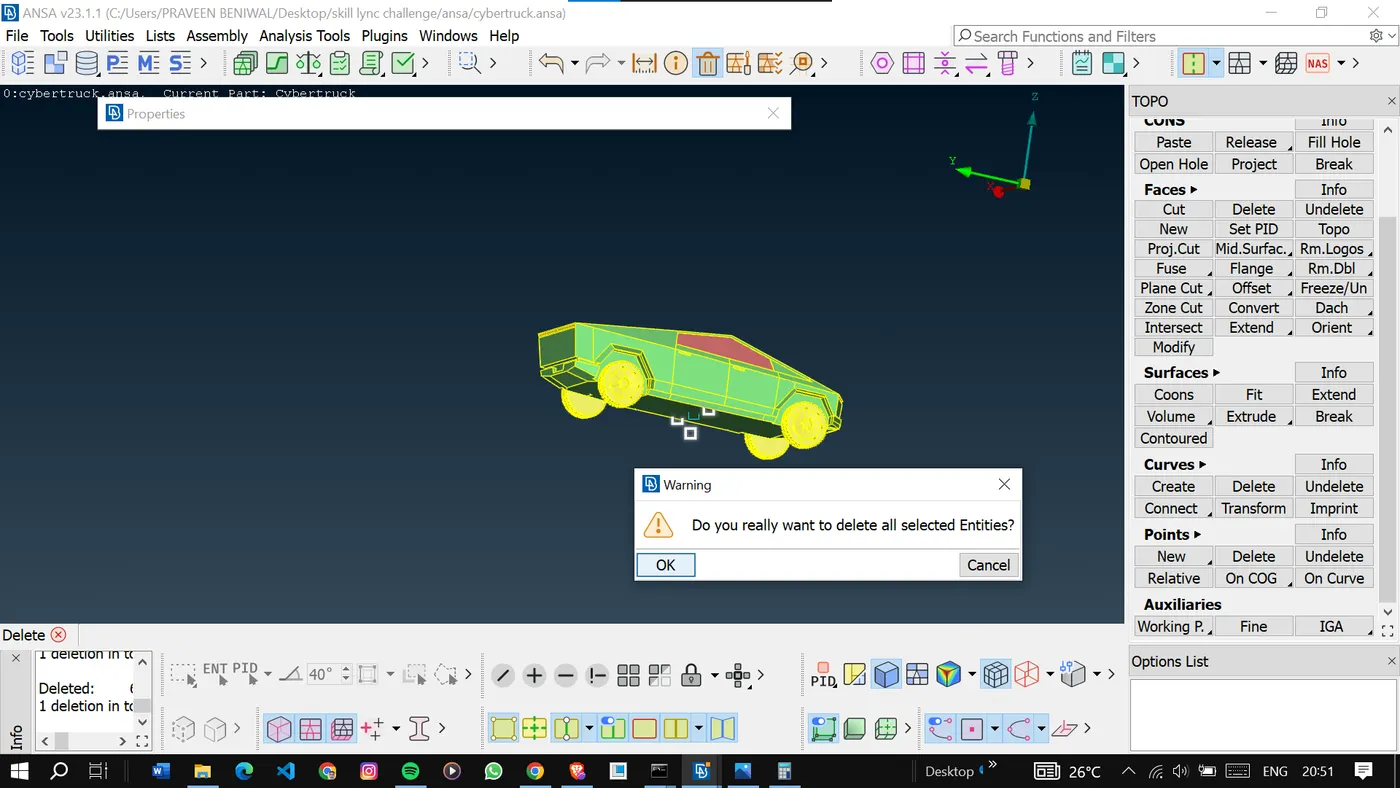
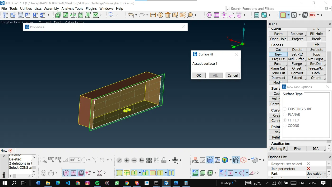
Make all the surfaces to form a closed volume.
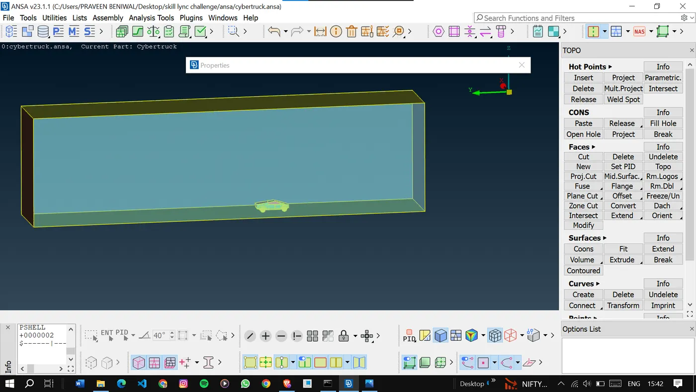
The target length used for the top surface is 400mm.
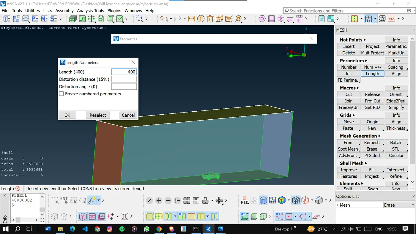
The target length used for the base surfaces is 20mm.
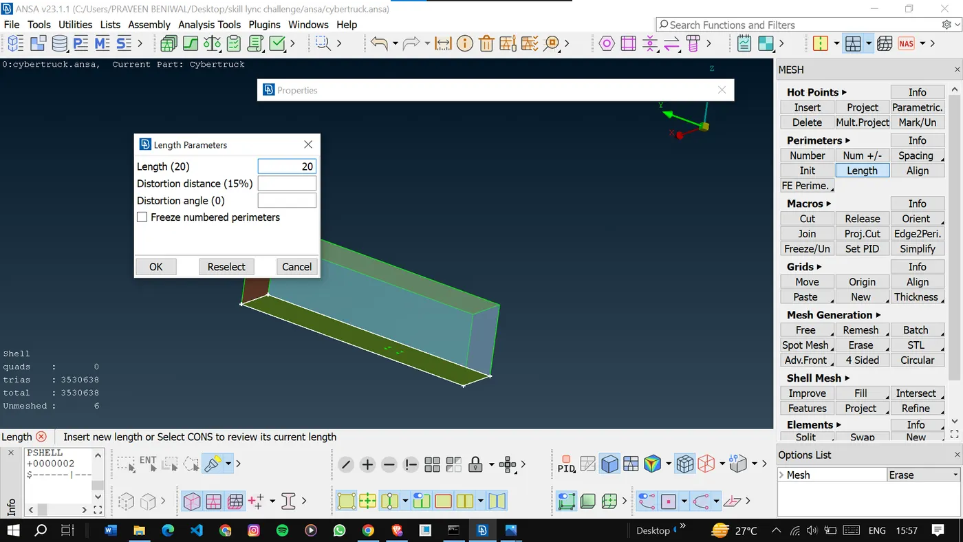
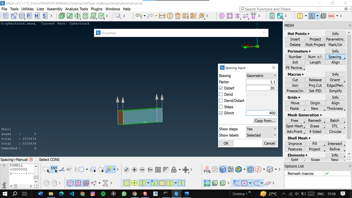
For side surfaces, we have used the spacing option for gradually increasing the target length. To avoid extra elements in the area out of our interest.
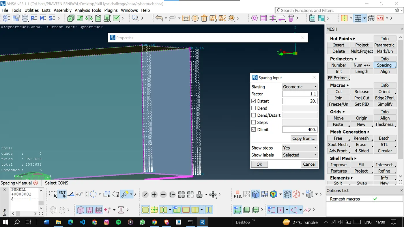
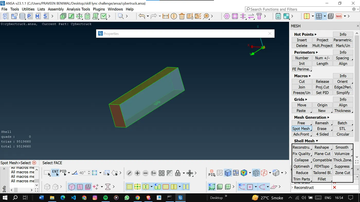
We have got 6 volumes here.
Our area of interest is volume 1 only.
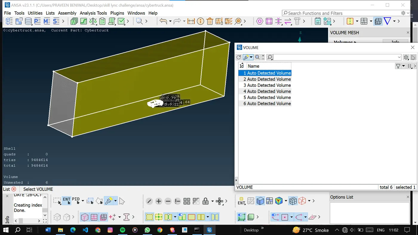
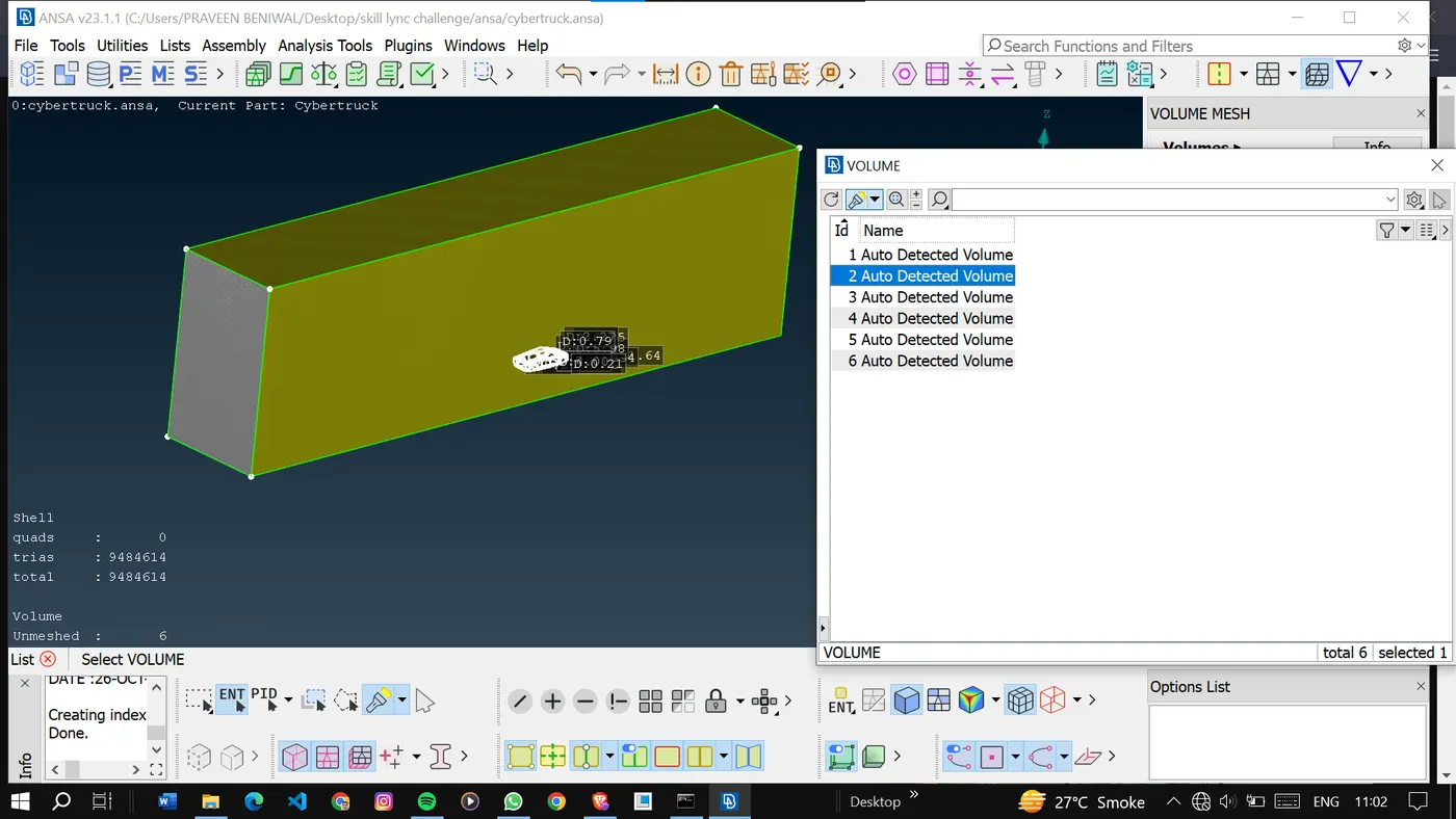
Delete the non-required volumes.
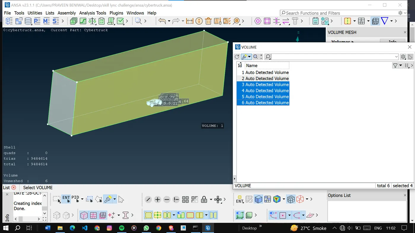
Here I have not performed the volumetric meshing as it takes a long time.
4. Quality Control:
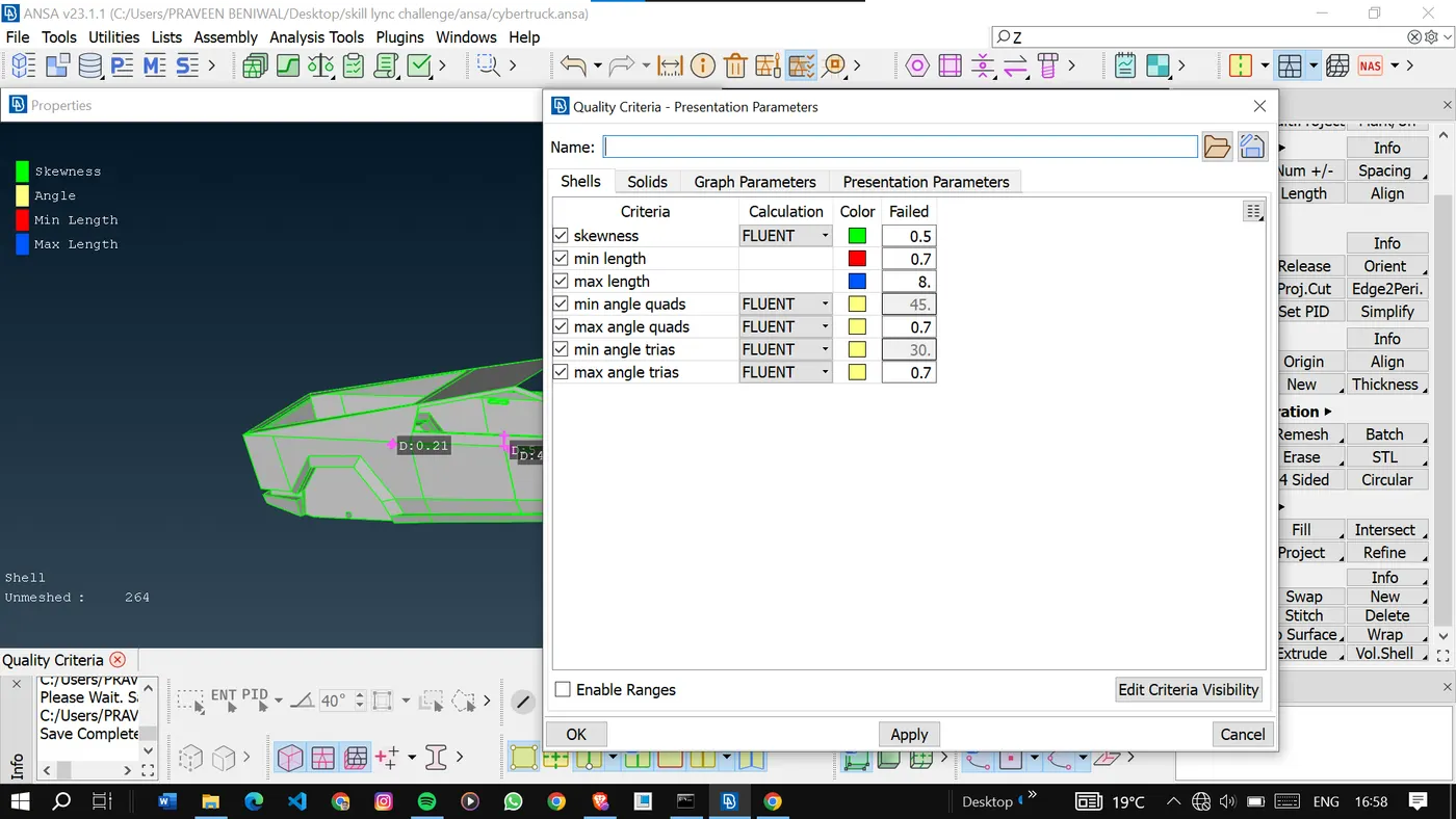
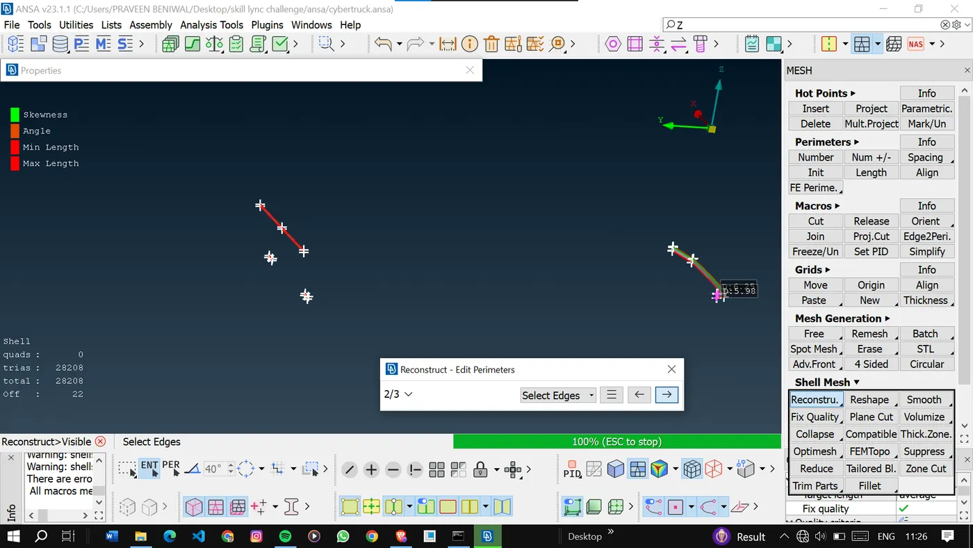
Checked the quality of the generated mesh by inspecting element metrics, such as min, max length, and skewness.
If any elements do not meet quality criteria, reconstruct and adjust the mesh parameters to improve element quality.
Learning Outcomes:
1. Geometry Cleaning: Identifying and addressing geometrical errors in CAD models.
2. PID Assignment: Understanding the importance of assigning Property IDs to different parts or materials.
3. Mesh Generation: Learning to control mesh size and element quality to achieve a balance between accuracy and processing time.
4. Quality Control: Developing the ability to evaluate mesh quality and make necessary adjustments.
Results:
Rectification of geometrical errors was carried out, followed by the creation of surface meshes that adhered to decided target lengths. Subsequently, volumes were generated for each component, with a focus on precision in meshing.
Conclusion:
In conclusion, the report has provided a detailed explanation of the process involved in rectifying geometrical errors, creating surface and volume meshes, and assigning Process IDs to different components in the given model. By following the decided target lengths and employing advanced meshing techniques, a precise depiction of the geometry has been attained. This meticulously crafted and clearly defined mesh will serve as a solid basis for future simulations and analyses, ensuring the production of precise and dependable results.