Week 3 Challenge : CFD meshing on Turbocharger
Question:-
For the given model, check for the geometrical errors to make appropriate volumes. Create and assign PIDs as shown in the video. Perform surface mesh with the given target lengths as per PIDs.
1. Blade stage-1 = 1 mm
2. Blade stage-2 = 1 mm
3. Impeller = 2 mm
4. Shaft rotor = 1 mm
5. Turbo casing = 5 mm
6. Compressor casing = 5 mm
7. Inlet casing cover = 5 mm
Perform Volumetric mesh for the required volumes as shown in the videos.
Write a detailed report on your surface meshing and volume meshing process.
Answer:-
https://drive.google.com/file/d/1lWprF_vEziFVMosnFYlAKZL3WYCsYlFl/view?usp=sharing link for ansa file
Aim:-
The primary objectives are to identify and rectify any geometrical errors present in the model, create and assign Process IDs (PIDs) according to specifications, perform surface meshing with prescribed target lengths based on PIDs, and finally generate volumetric meshes for the required volumes.
Introduction:-
Accurate meshing of geometrical components is crucial in computational simulations and analysis, particularly in fields such as fluid dynamics and structural analysis. Meshing serves as the bridge between the continuous geometry of the model and the discrete numerical calculations performed by simulation software. In this report, we present the methodology employed to rectify geometrical errors, generate surface meshes, assign PIDs, and create volume meshes for various components in the provided model.
Procedure:
<!-- [if !supportLists]-->1. <!--[endif]-->Geometrical Error Correction: The first step in the meshing process involved identifying and rectifying geometrical errors present in the given model.
Open the model in the ANSA pre-processor.
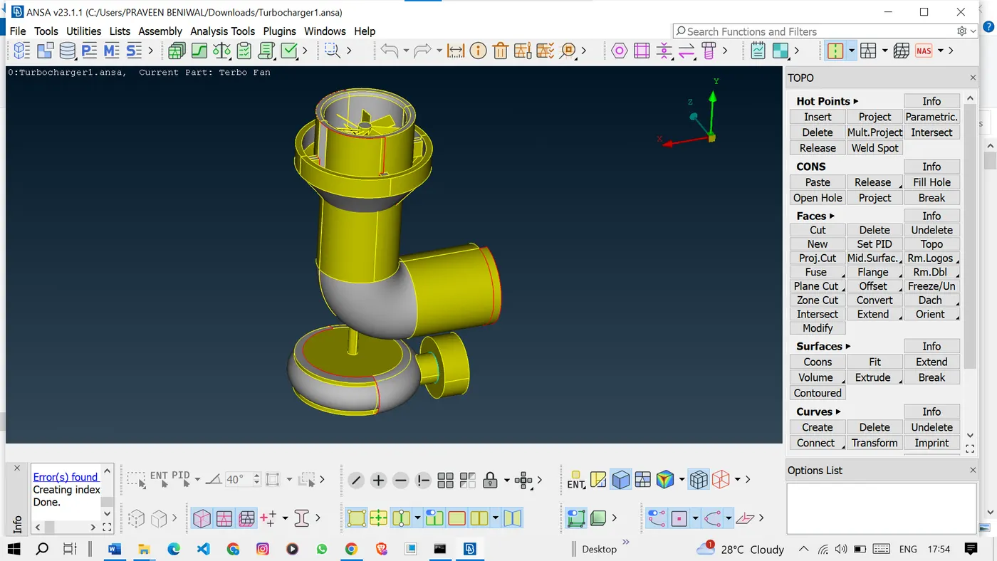
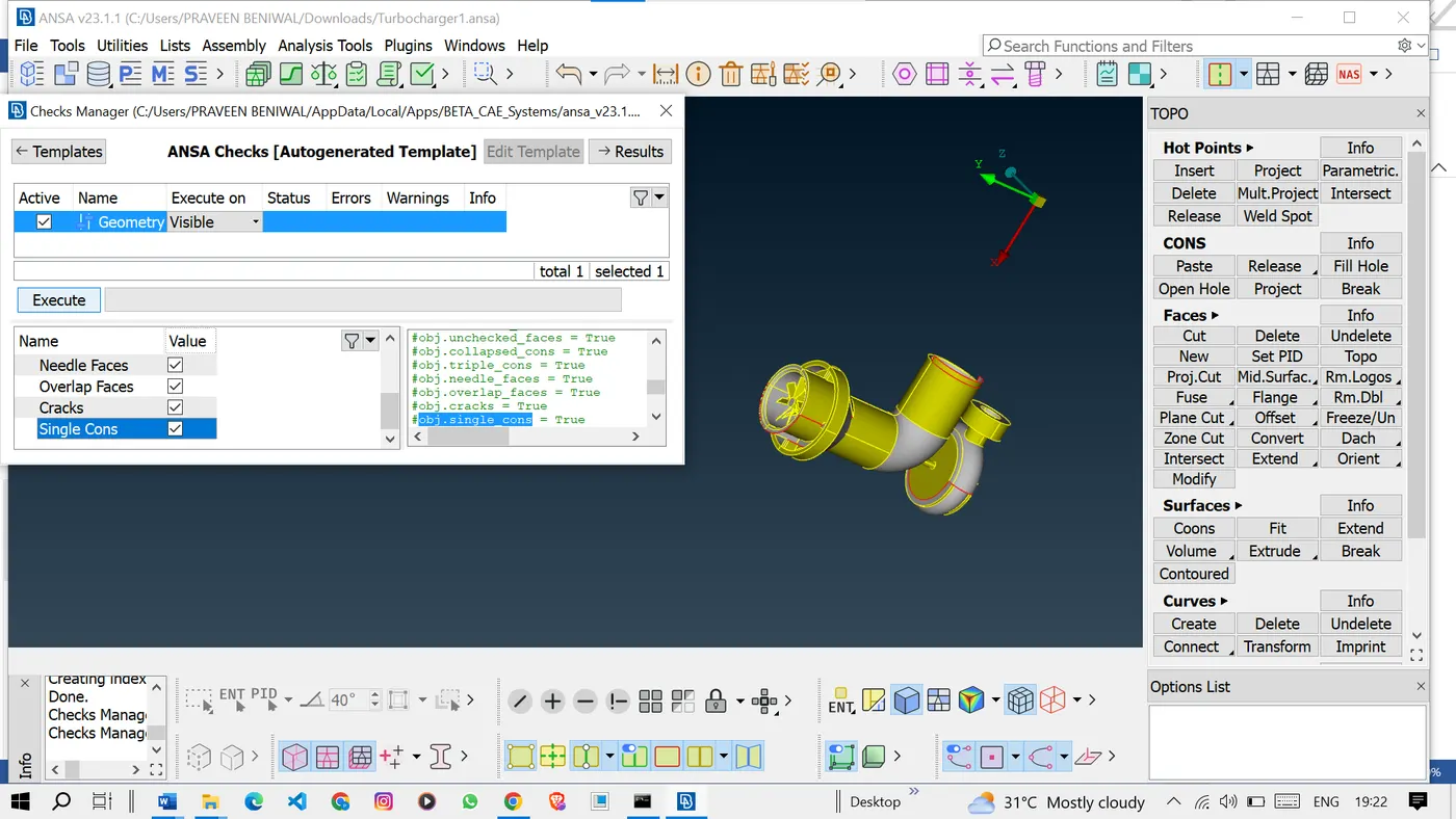
Then we will go with geometry checks.
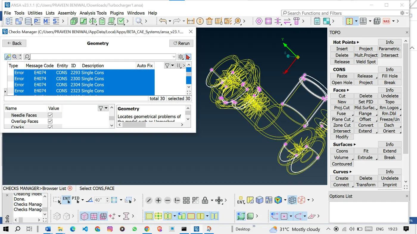
Here we can see some single cons are present in the model.
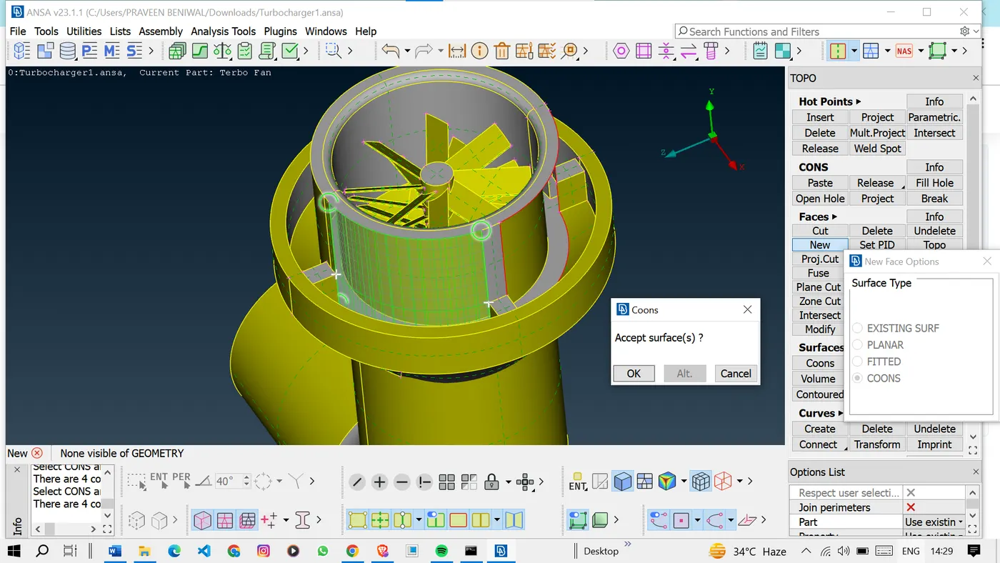
To patch the missing surfaces in the model we will go with the new under-the-FACES option in TOPO mode and we will patch the surfaces using the options present in the new option.
We can also use the fill-hole option to patch the surface if required.
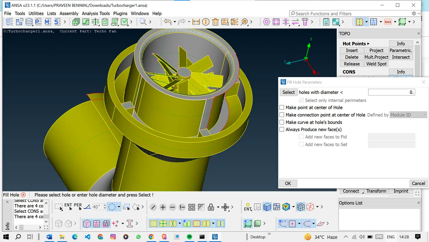
But in my case, the fill hole is not working so I will go with the new coons.
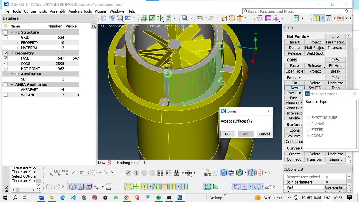
Here we can see the two surfaces intersecting each other and making single cons.
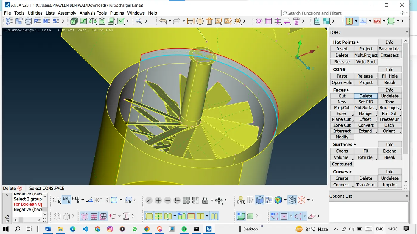
So to correct this intersecting face we will use the intersect option to form an intersection line at the intersection.
Once we get the triple cons there we can delete the unwanted surfaces using the delete option.
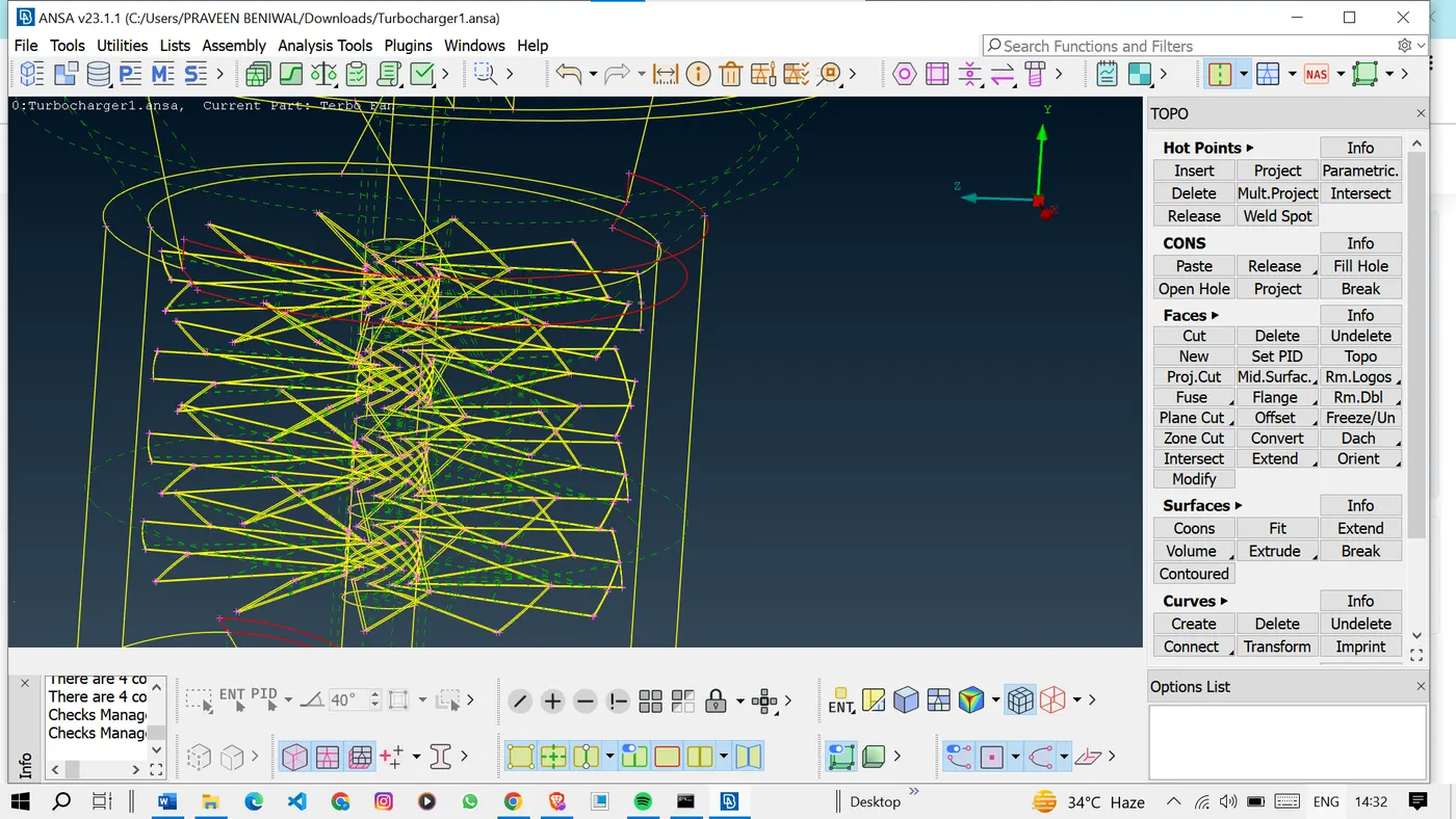
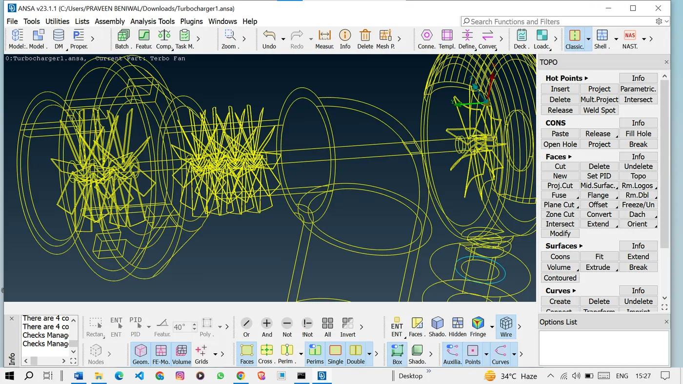
Now we will again see if some more single cons are present or not by switching to the wireframe mode.
As we can see some single cons so, again we will try to correct these also.
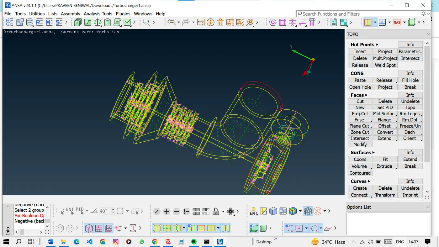
To patch this surface no option is generating the surface so we will go with another method by patching the surface using multiple small surfaces.
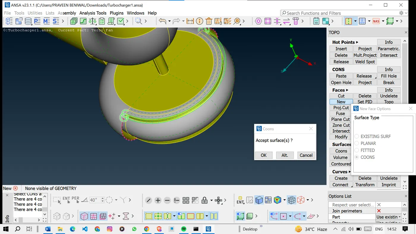
As we can see the surface is patched using many surfaces. we have used these many surfaces to achieve fine geometry.
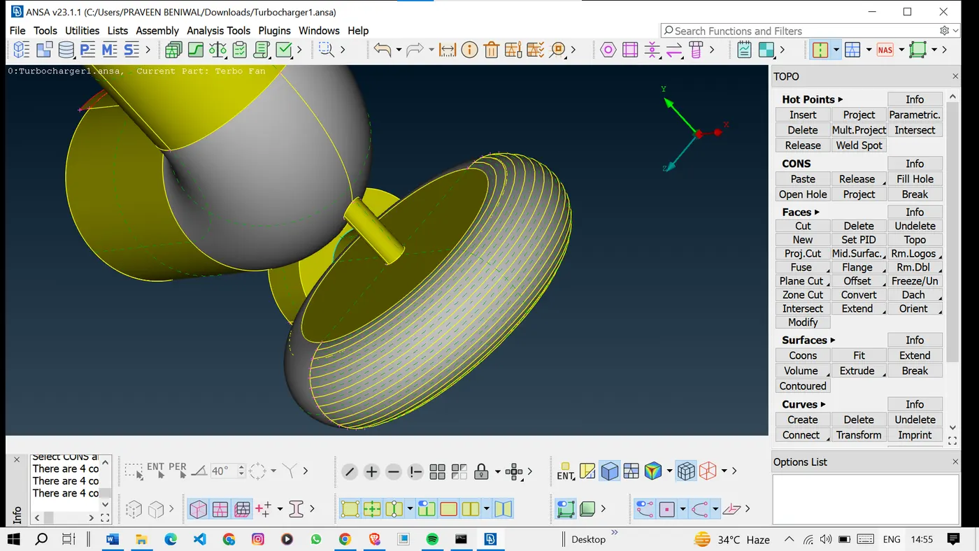
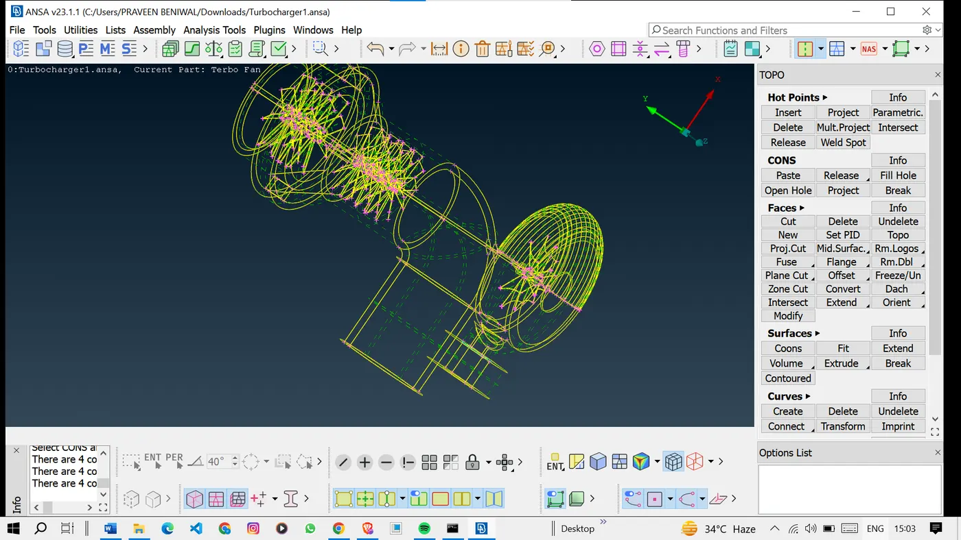
Once we have done with the patching and topological cleanup, once again check the model if there are any single cons present or not.
As we see there are no single cons present in the model.
<!-- [if gte vml 1]>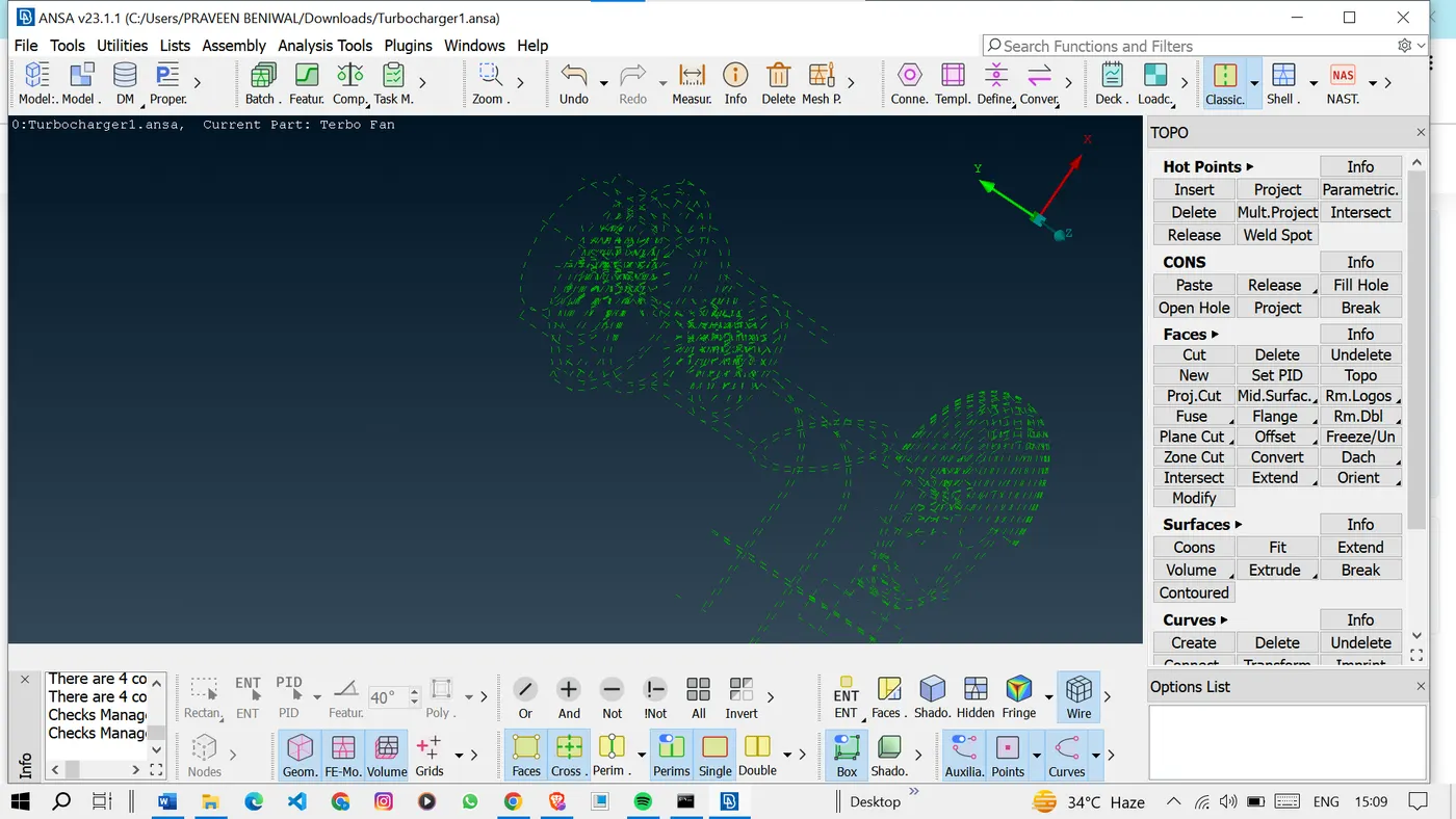
Now we can go for the PID assignment.
<!-- [if !supportLists]-->2. <!--[endif]-->PID Assignment and Surface Meshing: Surface meshing is the process of dividing the surfaces of the geometry into smaller elements to prepare for volume meshing. The following target lengths were assigned to specific components:
• Blade stage-1: 1 mm
• Blade stage-2: 1 mm
• Impeller: 2 mm
• Shaft rotor: 1 mm
• Turbo casing: 5 mm
• Compressor casing: 5 mm
• Inlet casing cover: 5 mm
To facilitate further meshing processes, PIDs were assigned to each component.
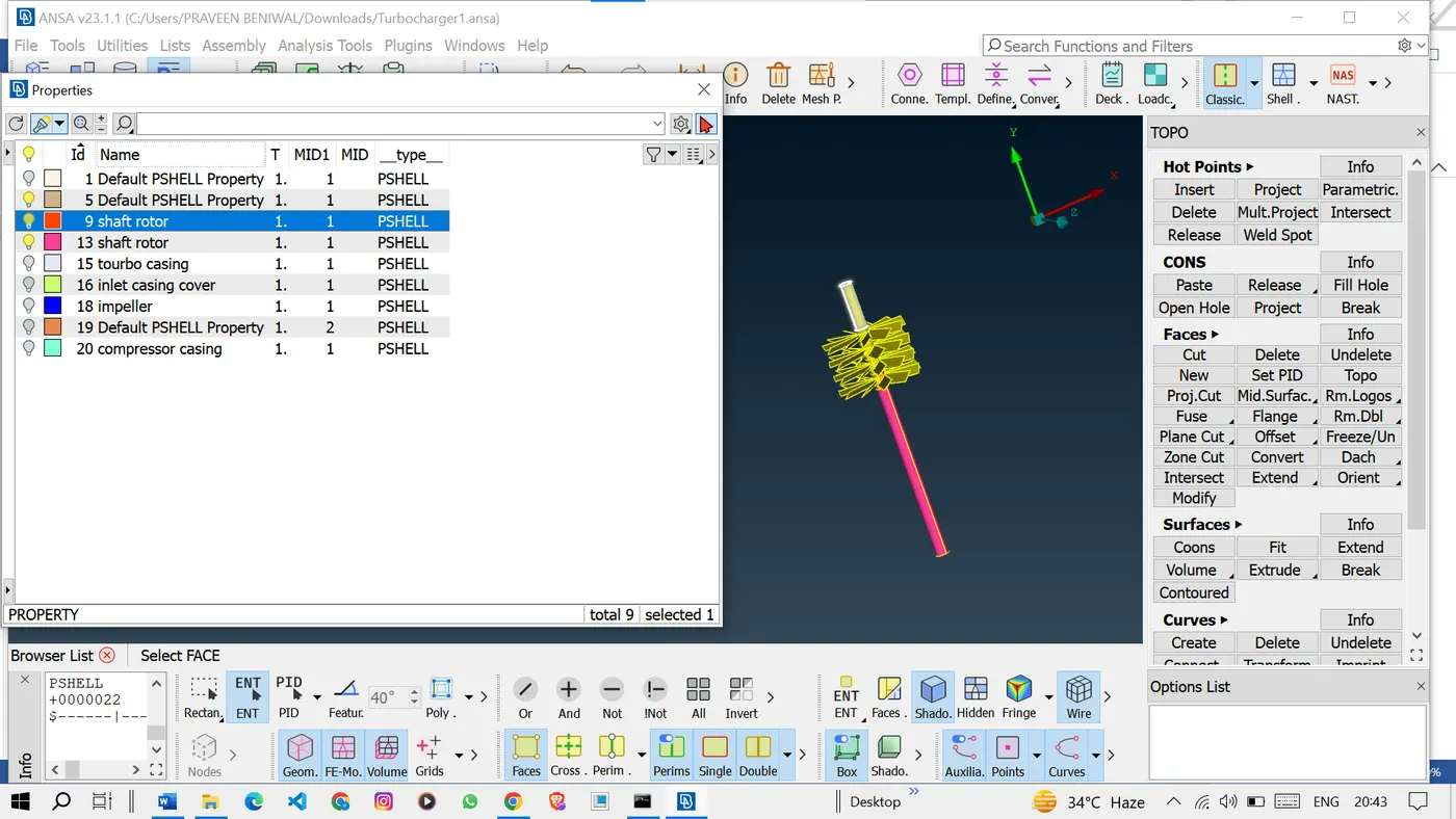
Once we have done with the PID assignment
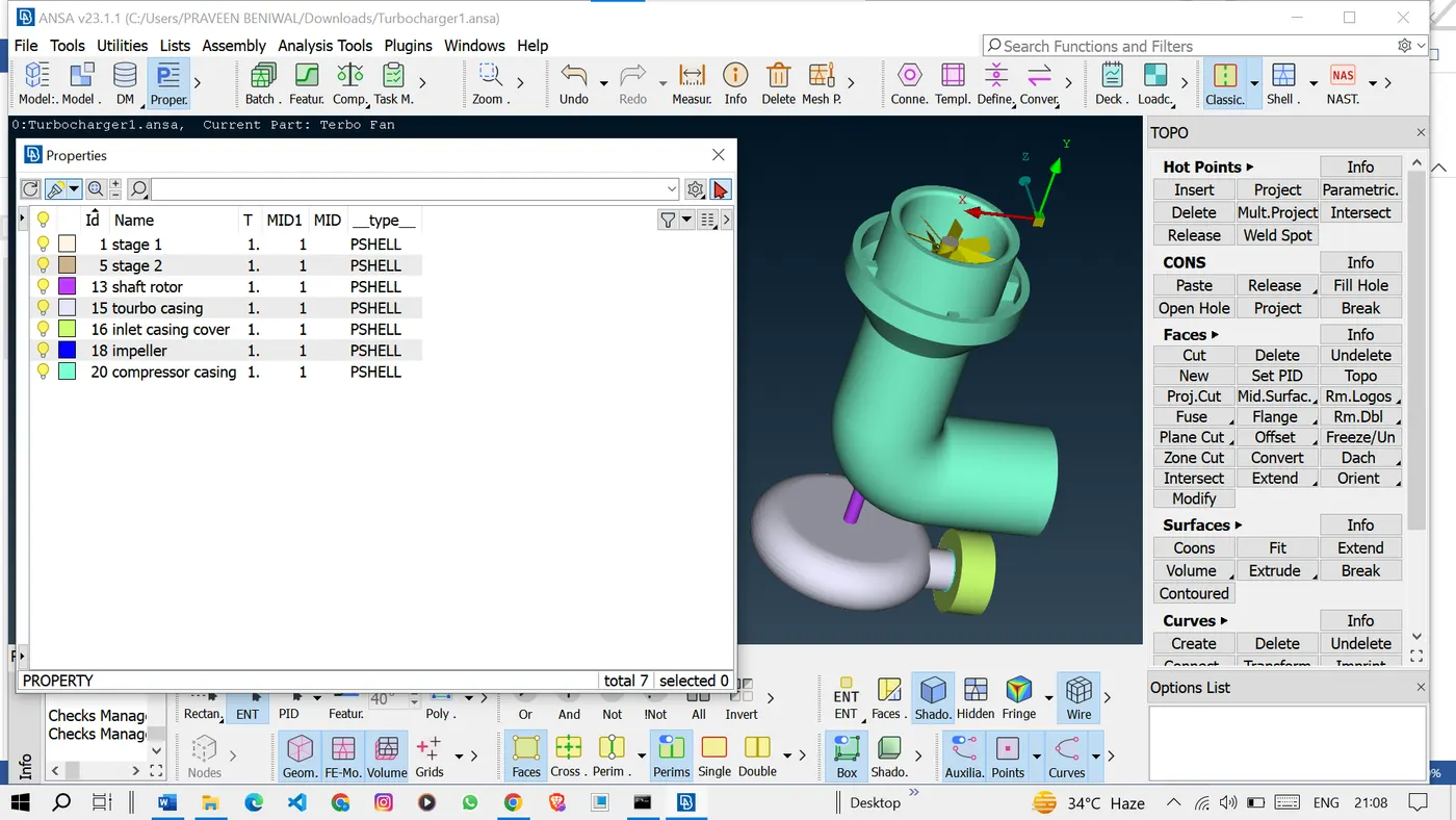
Now we will make some new PIDs to close the volumes.
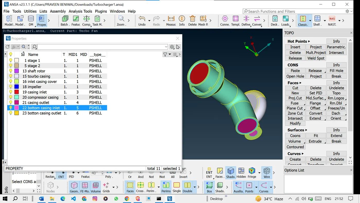
Now we will go for meshing the pids with given mesh lengths.
Surface Meshing Process: Surface meshing was conducted using an algorithm that divides each component's surface into smaller elements according to the specified target lengths. This process ensures that the mesh captures the intricacies of the geometry while maintaining the desired element size. It provides a foundation for subsequent volume mesh generation.
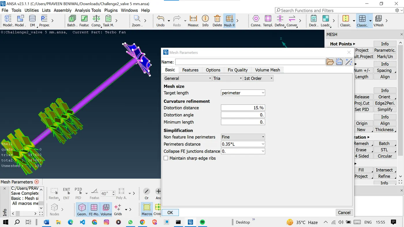
So to mesh the model we have to provide the mesh parameters and quality criteria for meshing.
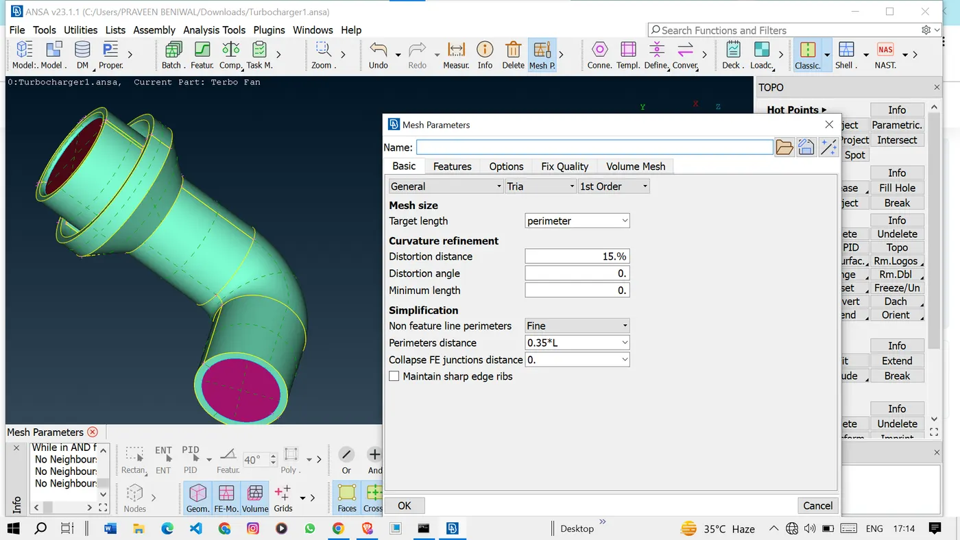
Enter the desired mesh length.
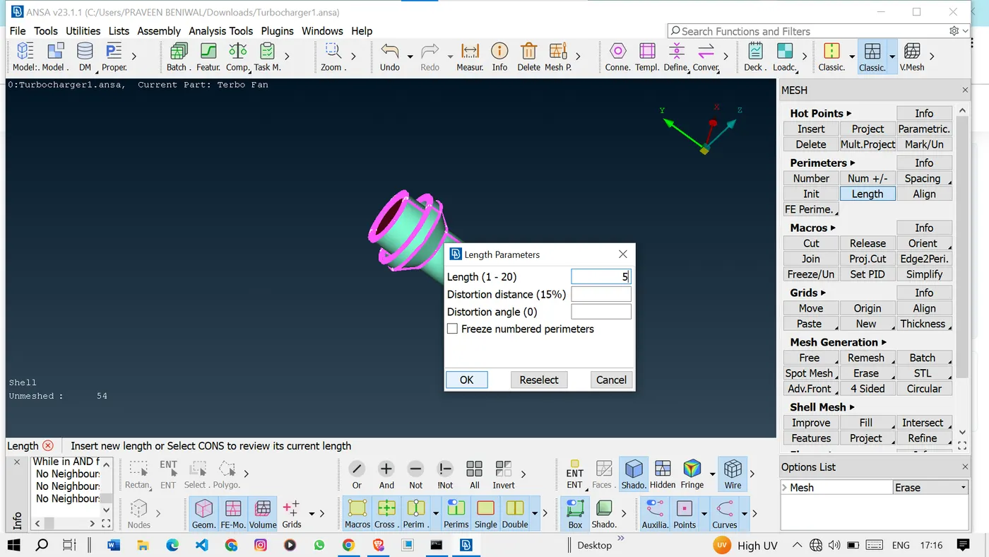
Similarly, mesh the other PIDs with the given mesh lengths.
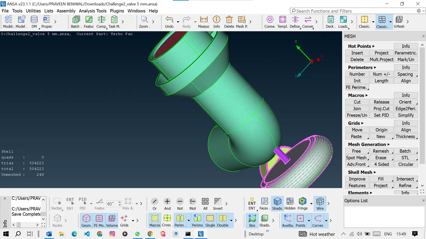
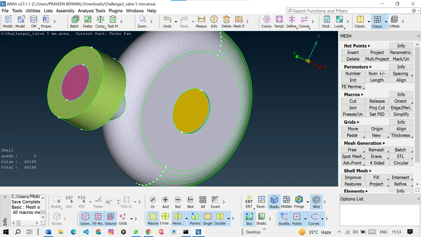
Meshed the turbo casing with a 5mm mesh length.
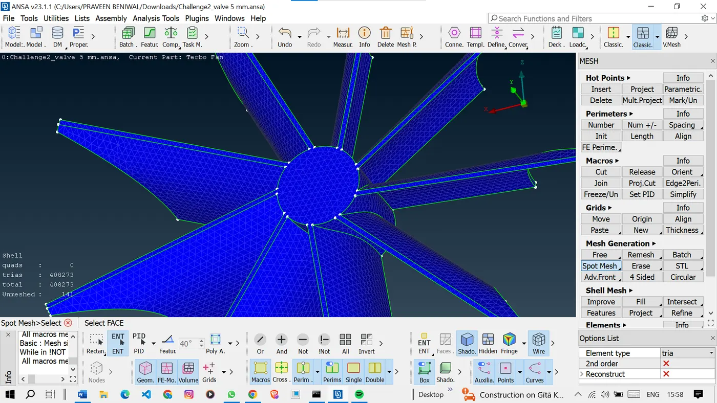
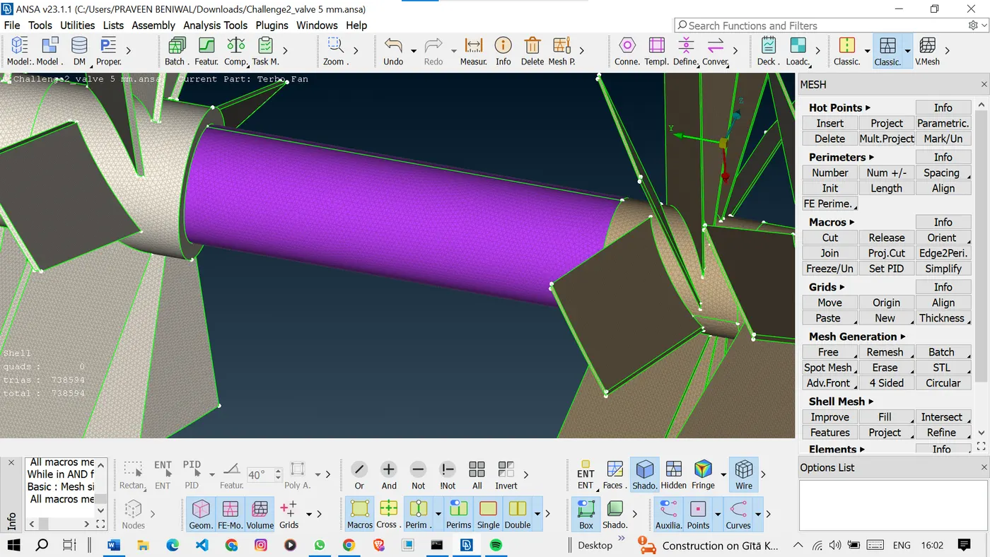
And meshed the rotor shaft, stage 1, and stage 2 with a 1mm length.
<!-- [if gte vml 1]>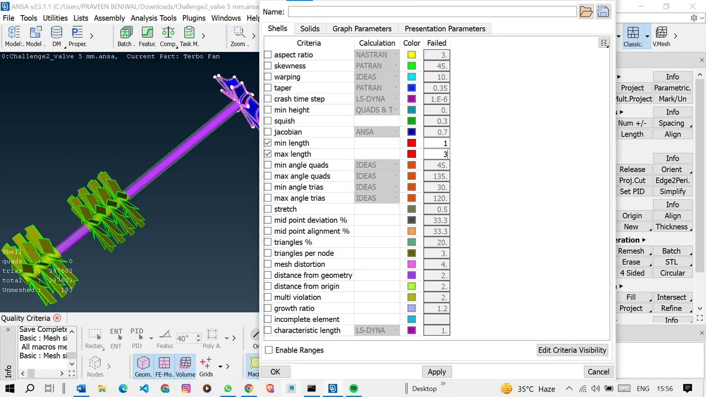
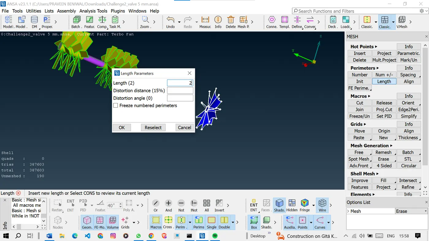
And also meshed the impeller with a 2mm mesh length.
<!-- [if gte vml 1]>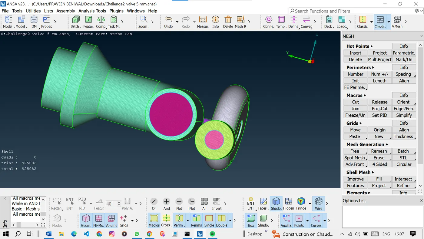
The meshing is completed but as we can see here some part is not meshed, it is because of different mesh lengths sharing the double cons.
So to mesh this region just avoid giving the mesh length but directly mesh the region so It will automatically adjust with the mesh lengths.
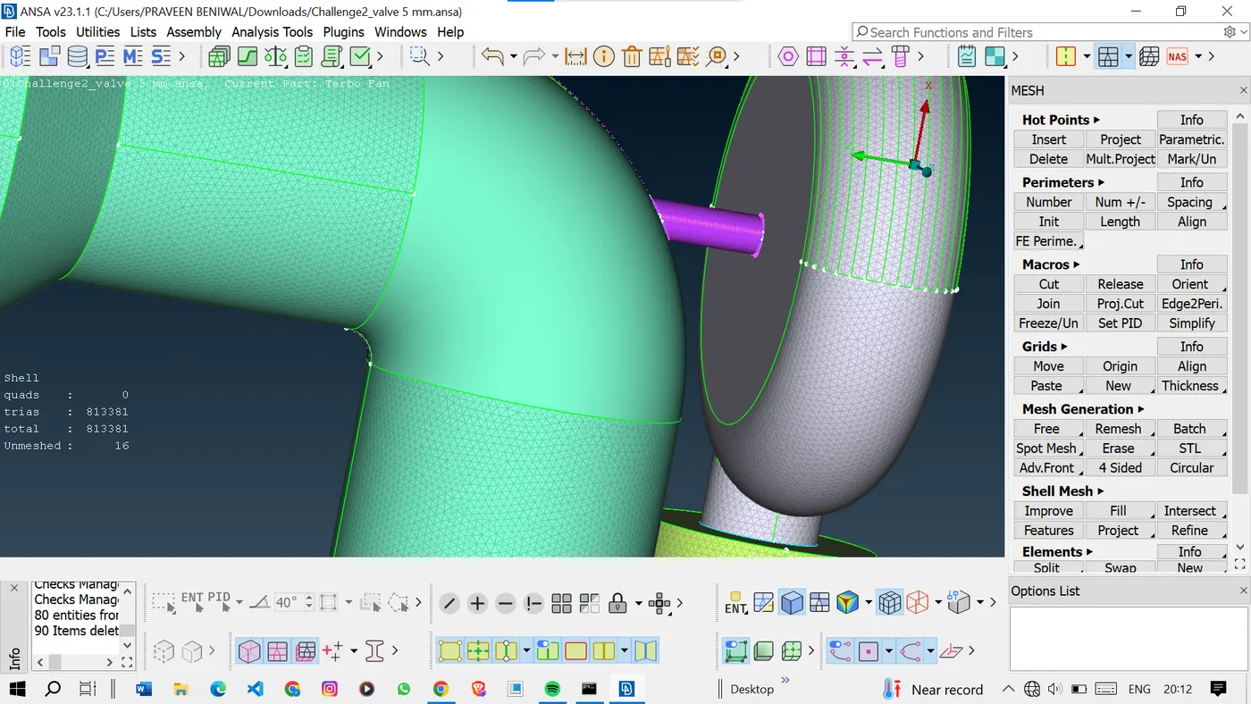
Here we can see that the meshing is done and it are automatically adjusted the lengths.
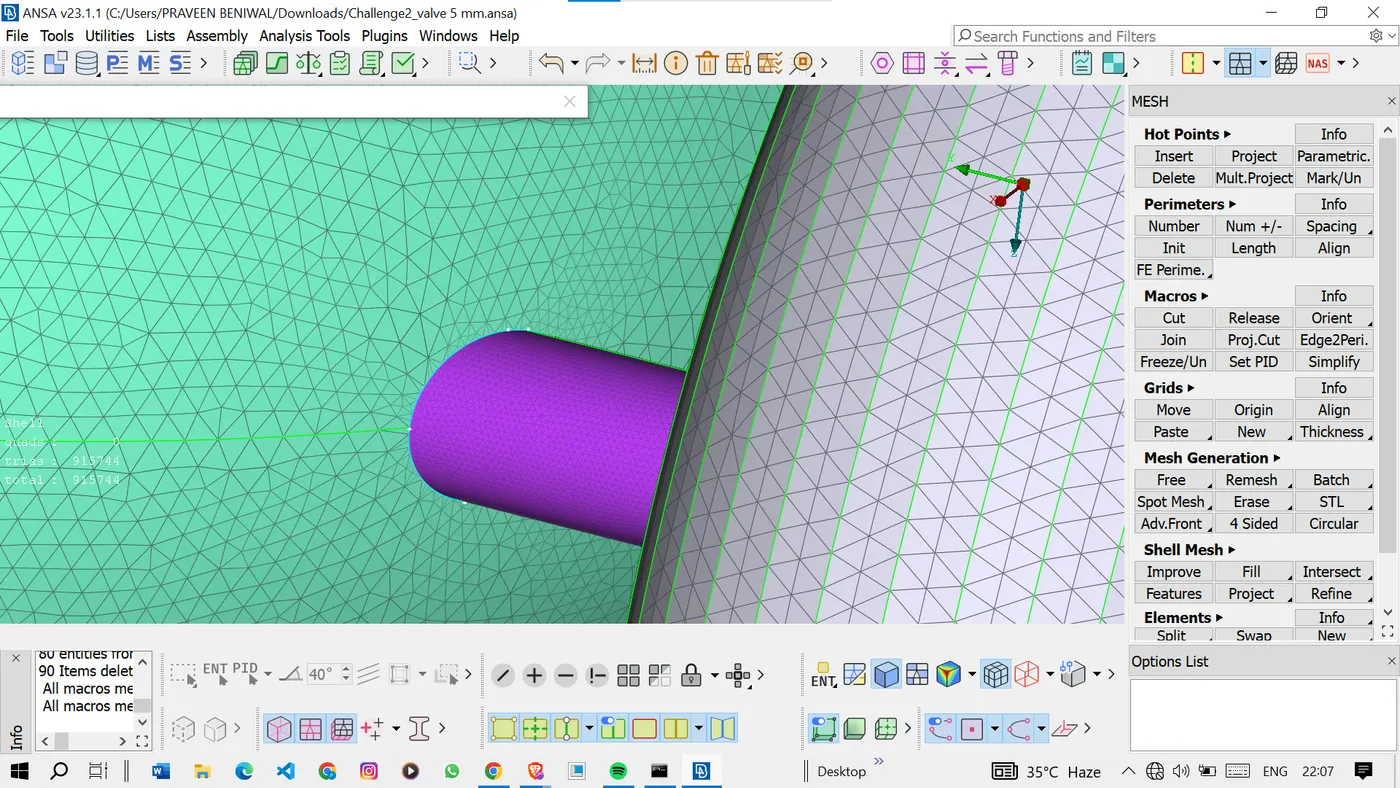
Now it's time for volumetric meshing.
<!-- [if !supportLists]-->3. <!--[endif]-->Volume Meshing Process: Volume meshing, also known as volumetric meshing or 3D meshing, involves creating mesh elements within the volume defined by the surfaces. The surface mesh serves as a guide for generating these elements while adhering to the specified target lengths. Volume meshing was performed for each component using a technique that ensures a consistent and accurate mesh distribution throughout the volumes.
Volumetric Mesh for Required Volumes: The volumetric meshing process generated mesh elements within the volumes of the components based on the established surface meshes and target lengths. This volumetric mesh is essential for accurate simulations and analyses, as it discretizes the entire geometry and allows for numerical computations on a discrete grid.
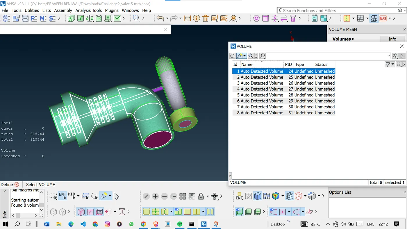
Now we will define the volumes for which we want the volumetric mesh.
Go to volume mesh >volume>define>click ok.
<!-- [if gte vml 1]>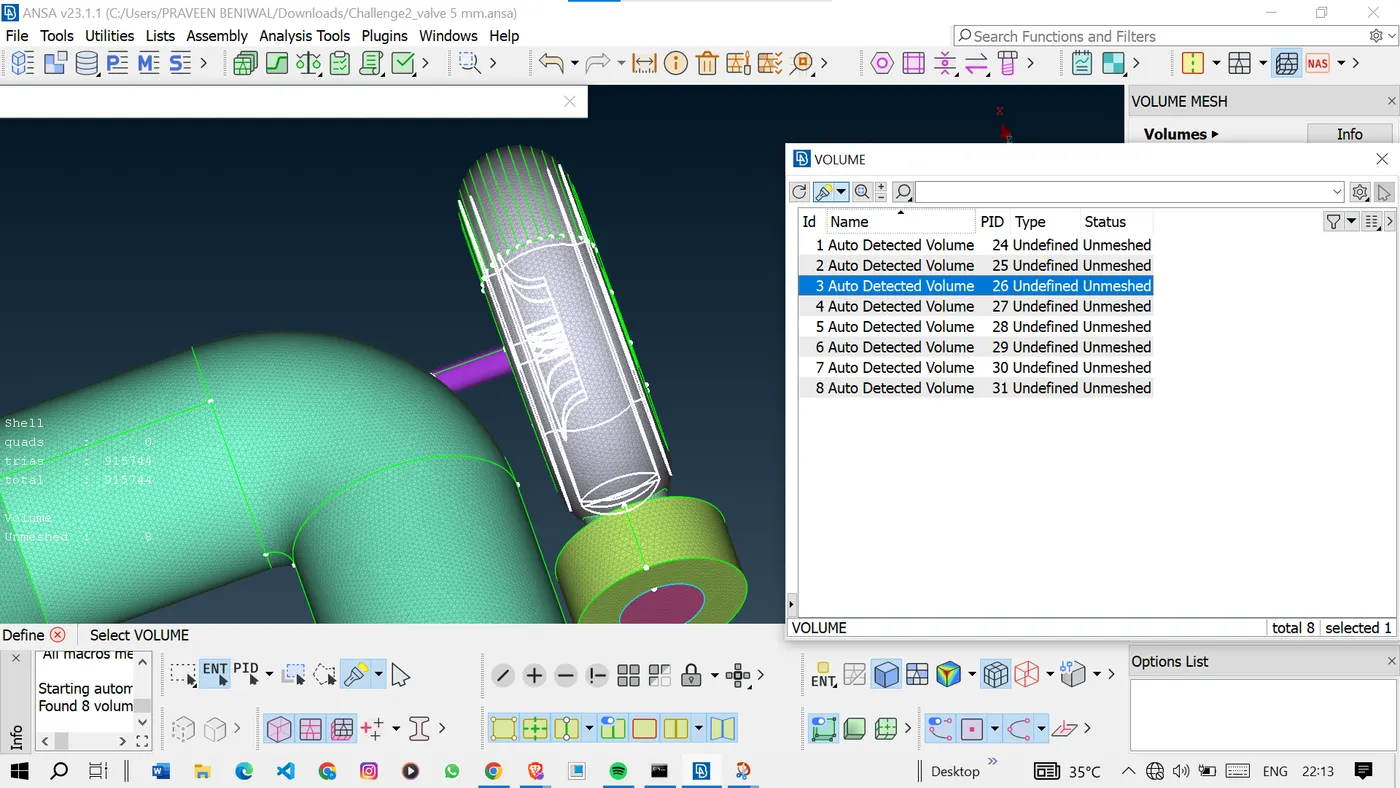
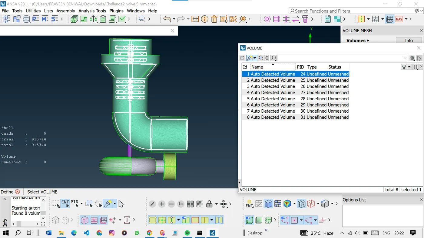
Analyze the volumes defined by the system and then delete the unwanted volumes
Right-click the volume you want to delete and select the delete option to delete them.
<!-- [if gte vml 1]>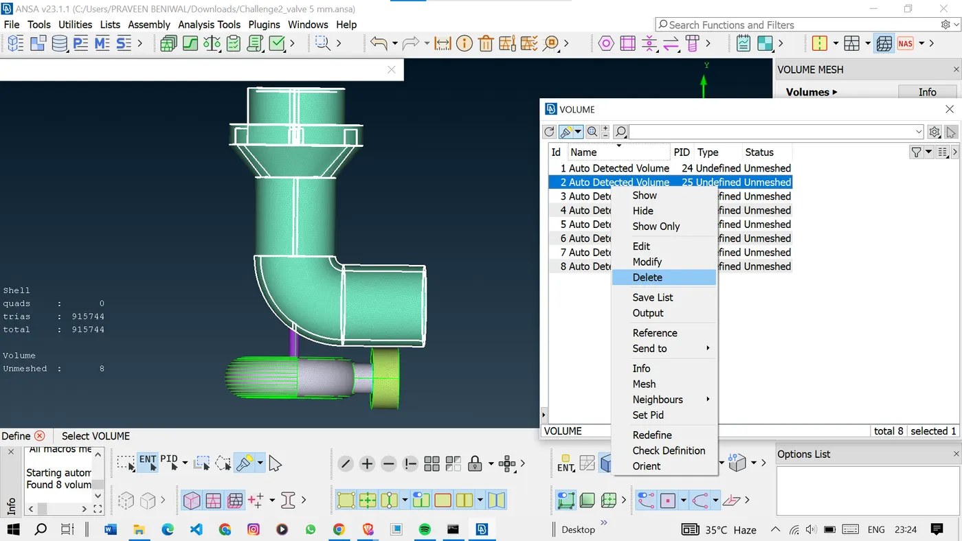
Now we are left with the required volumes only.
<!-- [if gte vml 1]>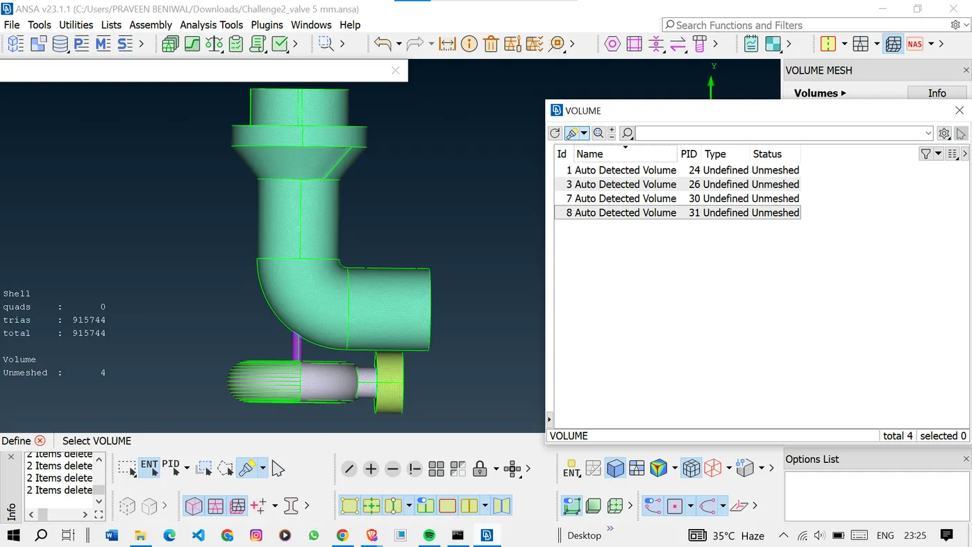
After deleting the unwanted volumes.
Select the type as tetra CFD and mesh one by one by right-clicking and selecting the mesh option.
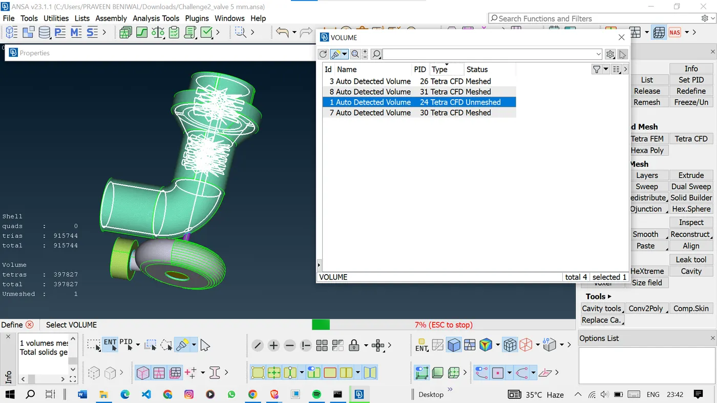
<!-- [if gte vml 1]>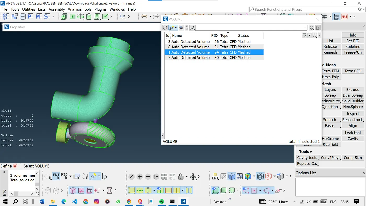
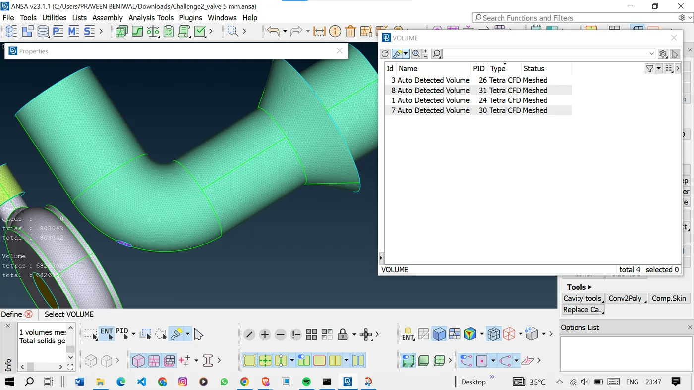
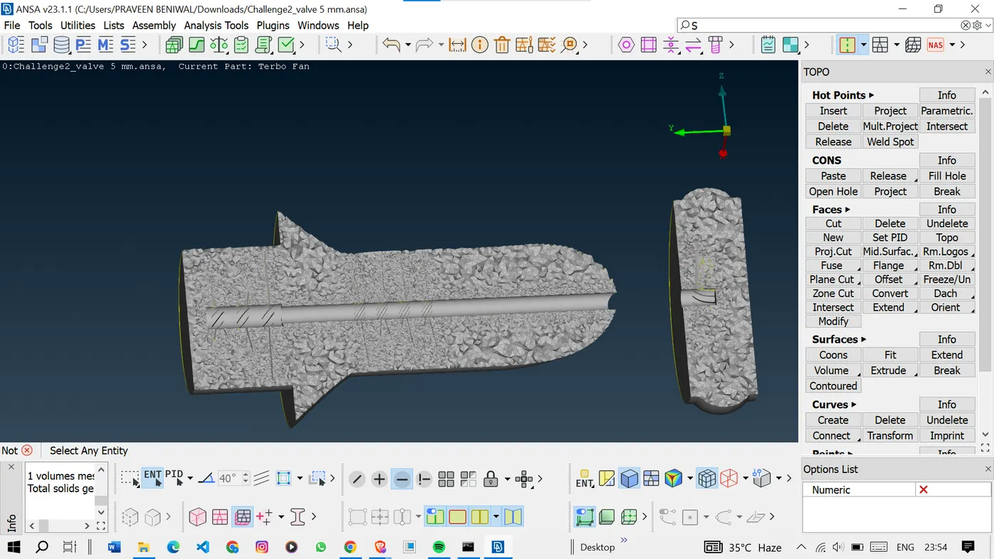
Now all the meshing part is done.
Here we can see the glitching these are nothing but the surface and volumes are overlapped.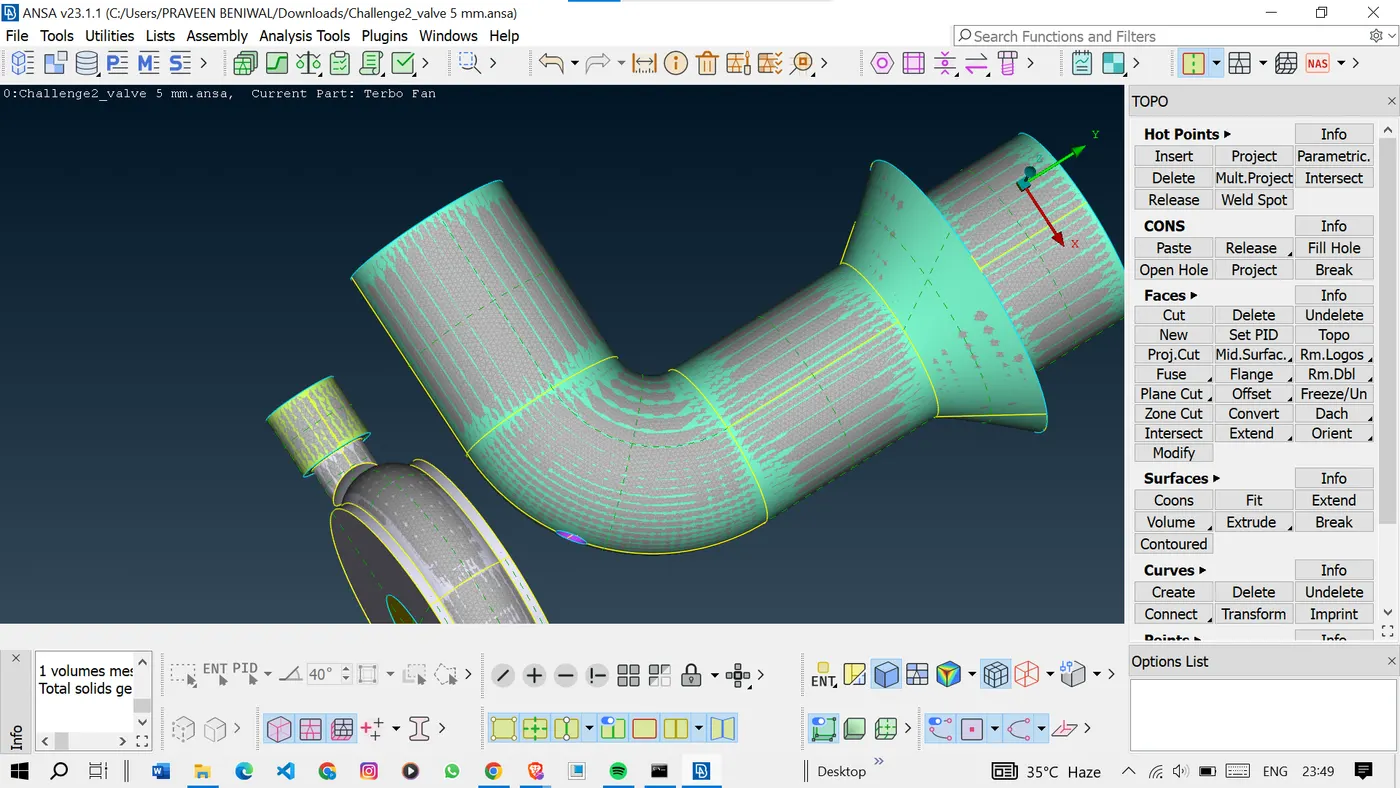
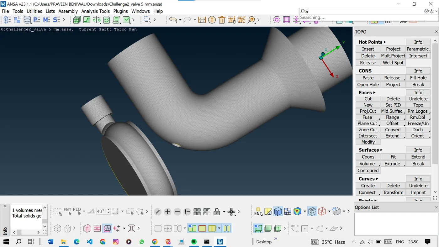
We can see only volume by turning off the geometry and FE. Mode in the visibility tools.
We can check volume at different sections using the not option.
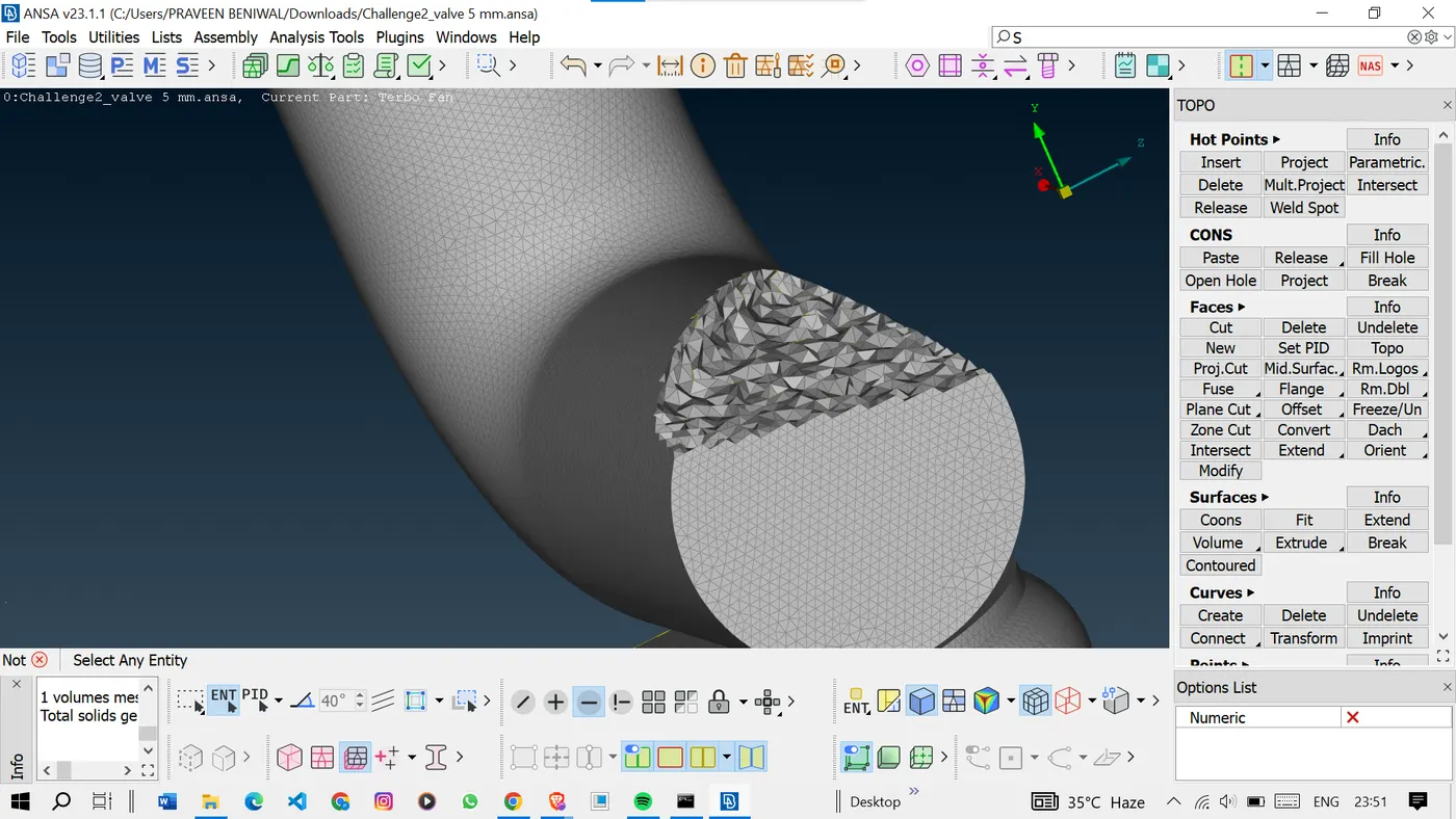
As we can see we have got a very good volume.
<!-- [if gte vml 1]>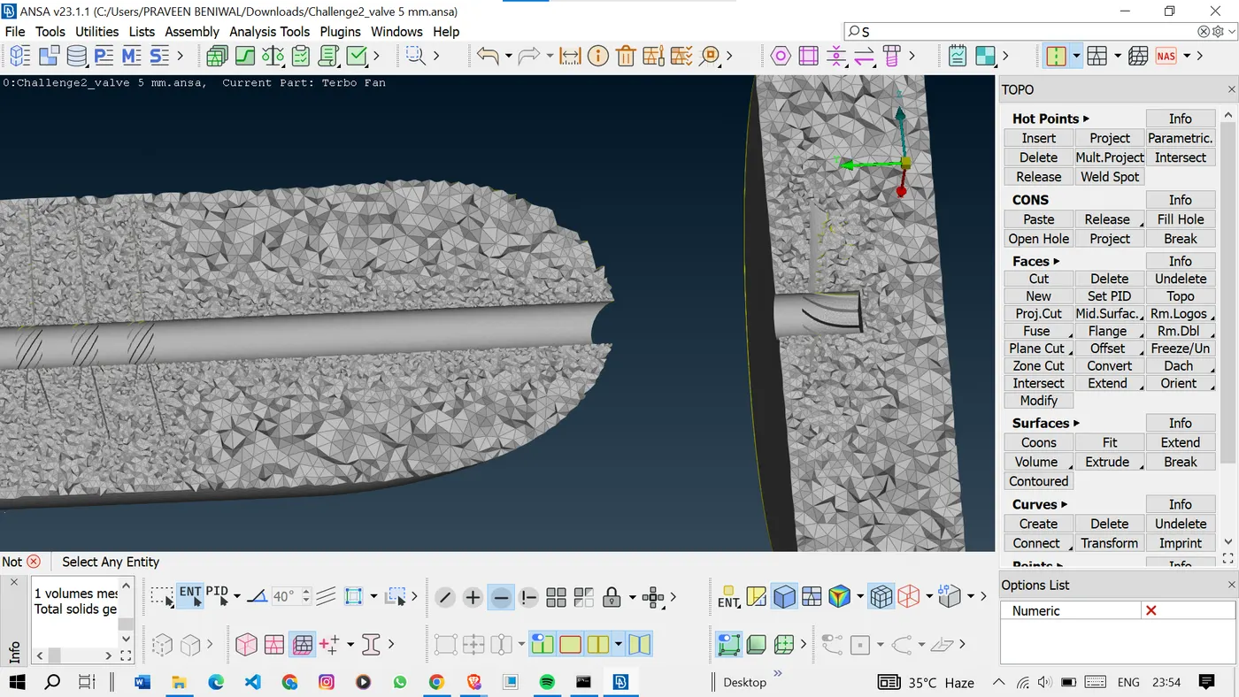
Result:
Geometrical errors were rectified, and surface meshes were created, adhering to designated target lengths. Subsequently, volumetric meshes were generated for each component, ensuring precision in meshing.
Conclusion:
In conclusion, this report has outlined the comprehensive process of correcting geometrical errors, generating surface and volume meshes, and assigning Process IDs for various components in the provided model. By adhering to the specified target lengths and utilizing advanced meshing techniques, an accurate representation of the geometry has been achieved. This clean and well-defined mesh will serve as a foundation for subsequent simulations and analyses, contributing to accurate and reliable results.