Week 4 Challenge : CFD Meshing for BMW car
Aim:
(i)To perform a geometric cleanup of the CAD Model of a BMW car.
(ii)To convert the multiple volume inside the geometry into one single Volume.
(iii)To create the windtunnel and the Surface mesh for the Whole model with the specific target lengths
(iv)To create the Volumetric mesh between the wind tunnel and the BMW car model.
Introduction:
ANSA preprocessor is a tool for bridging a gap between CAD and CFD.It Supports a various formats for importing such as popular CAD Formats (STEP,IGES,ParaSolid),CATIA V5,CATIA V6,Solid works,Inventor files,Unigraphics etc.ANSA provides a sufficient tools for various Topological issues and compare Tool can efficiently compare the geometrical differences between two models.ANSA provides a great flexiblity from manual to automation .Automation can be carried out in two ways (i)Task manager (ii)Scripting .Task manager is a tool that organizes all of the distinct modeling actions that must be followed for the setup of a discipline specific model.Scripting is a programming environment that enables the development of complex custom procedures which utilize both the existing capability of ANSA as well as user developed functions.ANSA provides many fully automatic and semi-automatic meshing tools. At the core of these tools are the unique proprietary meshing algorithms which are fast & robust and the Reconstuct/Reshape tools which allow the manipulation of mesh for improved mesh flow and quality.These tools can be used interactively or through the Batch Mesh Manager which integrates the tools to deliver a high quality result based on the User requirements.Treatment of CAD and existing legacy FE data can be handled through the tools, thus allowing an analyst to quickly coarsen or improve a mesh flow from an existing model.For water tight surface definitions, the Wrap tool can be used to quickly generate a high quality surface mesh based on User parameters without requiring extensive geometry manipulation.Volume meshing algorithms including fully automatic top down approach such as Hextreme which yields a hex dominant mesh with cut cells at the surface, and bottom up approaches using Tetrahedral, Pentahedral and Hexahedral elements. Layer generation is also possible with many controls for prism height, growth and control of quality.An Acoustic Cavity tool is available which provides a step by step wizard in generating the acoustic cavity mesh for Nastran or PERMAS. The analysts have control over the size of elements, number of sensor points and locations, the type of connection between the solid elements and the wetted surfaces. Also it can automatically create/update the appropriate ACMODL solver card.ANSA uses geometric entities to define the assembly data ,that are managed through the Connection Manager, which allows the analyst to define templates and use multiple built in definitions for the different FE representations.ANSA supports the include keywords, and provides the requisite tools to create, manage and output the include files from the database. Include files allow the analyst to break up the model into smaller sections thus only needing to update a portion of the model that incur changes.Extending this further, ANSA provides the Includes Configurator, which allows the User to select from multiple include files for a given loadcase.ANSA pioneered and successfully implemented the concept of interoperable decks between the supported solvers. This allows the user to directly switch between solvers with all supported entities mapping automatically and even synchronization of material information.The Laminate Tool is one more enhanced function that assists the modeling of complex parts made of composite materials. A single interface suffices the operation of creation & modification of layers, material orientation and definition of stack orders. ANSA provides various model checks to ensure model integrity and accuracy.The morphing tools are fully integrated in the ANSA environment. Morphing can be used to modify existing designs, link with optimization, or create new concepts for future studies.There are two main methods implemented inside ANSA, Domain based and Direct Morphing. Domain Based morphing requires the definition of control boxes assigned to the model in order to manipulate the shape. As the boxes are abstract, it provides significant flexibility and robustness in handling the most complicated cases.Direct Morphing works with existing features of the model thus reducing the effort and complexity required to make alterations.ANSA provides many advanced tools for specialized tasks, including a Cross-Section, Fuel Tank and Volume Trap tools.The Cross-Section analysis tool calculates the geometric properties for both thin and thick section. The sectional properties can be used to create Beam/Bar properties to be used in the respective solver Deck.The Tank tool generates a numerical analysis of the Volume vs Height of the fuel in the tank. This can be done for multiple orientations and helps determine the optimum filling and suction points.The Volume Trap tool investigates regions of trapped liquids during the immersion and extraction of the BiW (Body in White) bath analysis.One of the biggest advantages that ANSA delivers is the ease with which it can be coupled with an optimizer.
Procedure:
Procedure:
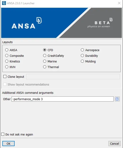
<!-- [if !supportLists]-->1. <!--[endif]-->Start->ANSA,opens up with the ANSA Launcher [removed] the layout section by default CFD is selected and Additional ANSA command arguments by default comes with -changedir it represents a change directory but necessary to change to -performance_mode 3 for having good drawing Quality and slower drawing performance.
<!-- [if !supportLists]-->2. <!--[endif]-->File->open the open window appears,locate the file then select the file and click open button .
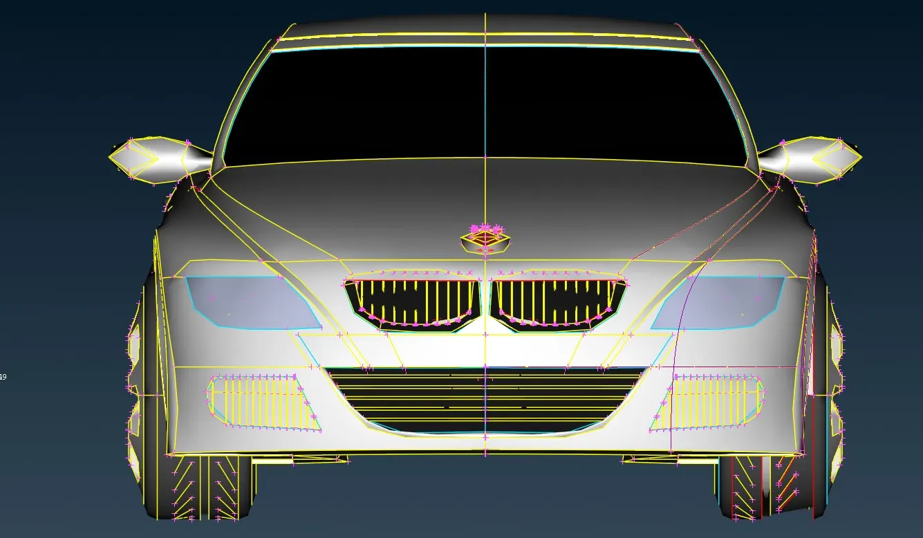
Model displayed ,curves are deteroited due to that model may not exactly replicates the designed model.
<!-- [if !supportLists]-->3. <!--[endif]-->For that auxilaries->fine option may usable selection of 3D curves using box select is not posible ,it should select one by one.Following this procedure is really difficult.Alternatively Mesh->Perimeters->length option is selected,selection window appears that consists of perimeters and macros option.perimeter is selected, using box select selected each and every segment present in the model and scroll button on the mouse is clicked then the length parameters window appears 1 is entered on the length and ok button is selected by using right mouse click,then the macros is selected then whole model is selected using box select and scroll button is clicked length parameters window appears entered the length as 1 and clicked ok button.
Length-This function defines the element length on selected perimeter segments or macro areas.
Fine-This function increases or decreases the presentation resolution of a selected 3D-curve, CONS segment or Face.
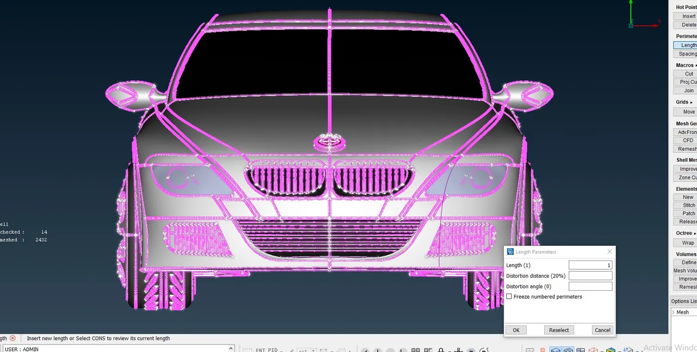
This step results in obtaining the displayed model similar to the designed model.
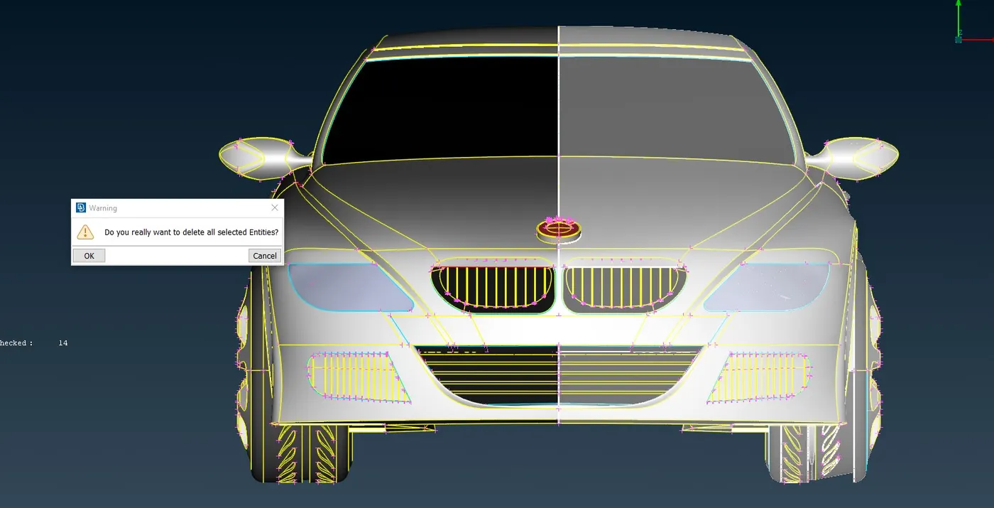
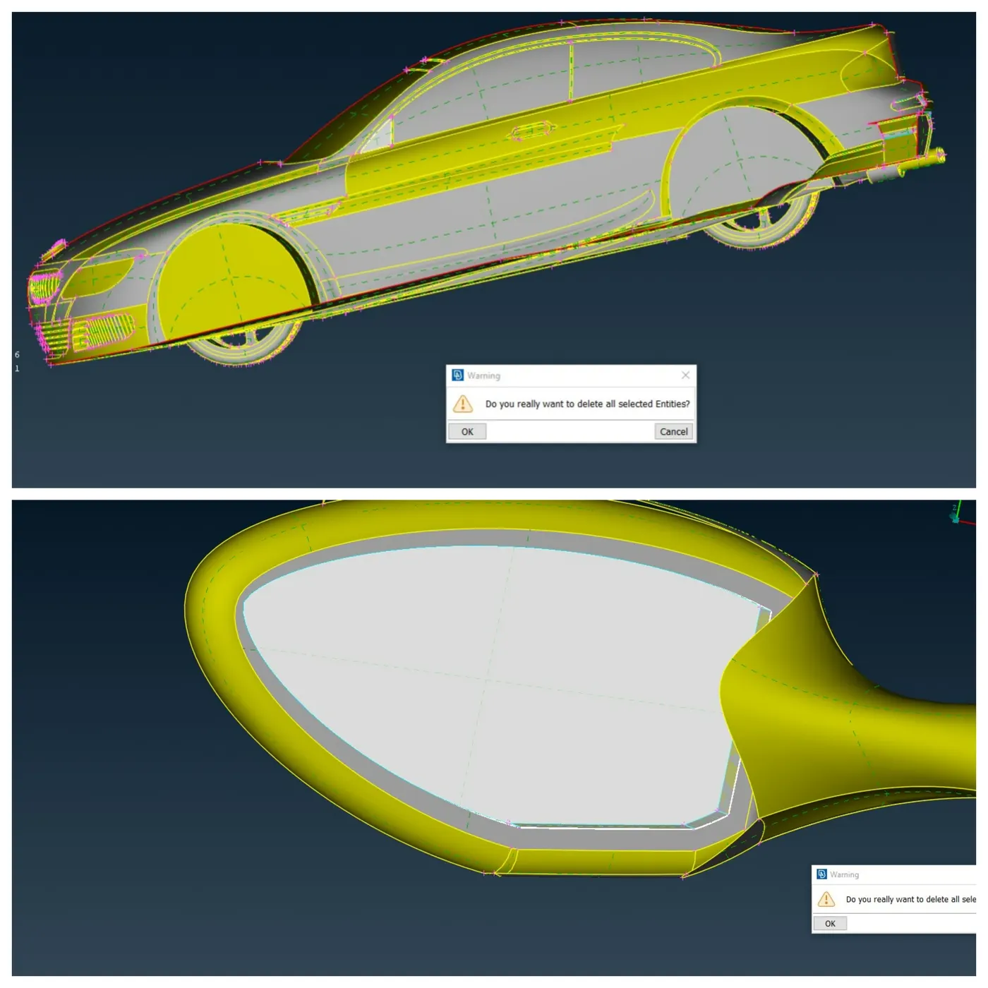
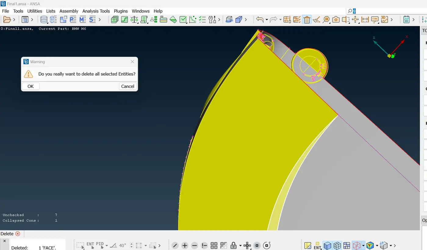
<!-- [if !supportLists]-->4. <!--[endif]-->Utilities->Delete option is used then using box select to select the entities of half of the model ,logo is deselected then middle mouse button is clicked,then Warning window appears click ok button.
Procedure for Deleting Surface:
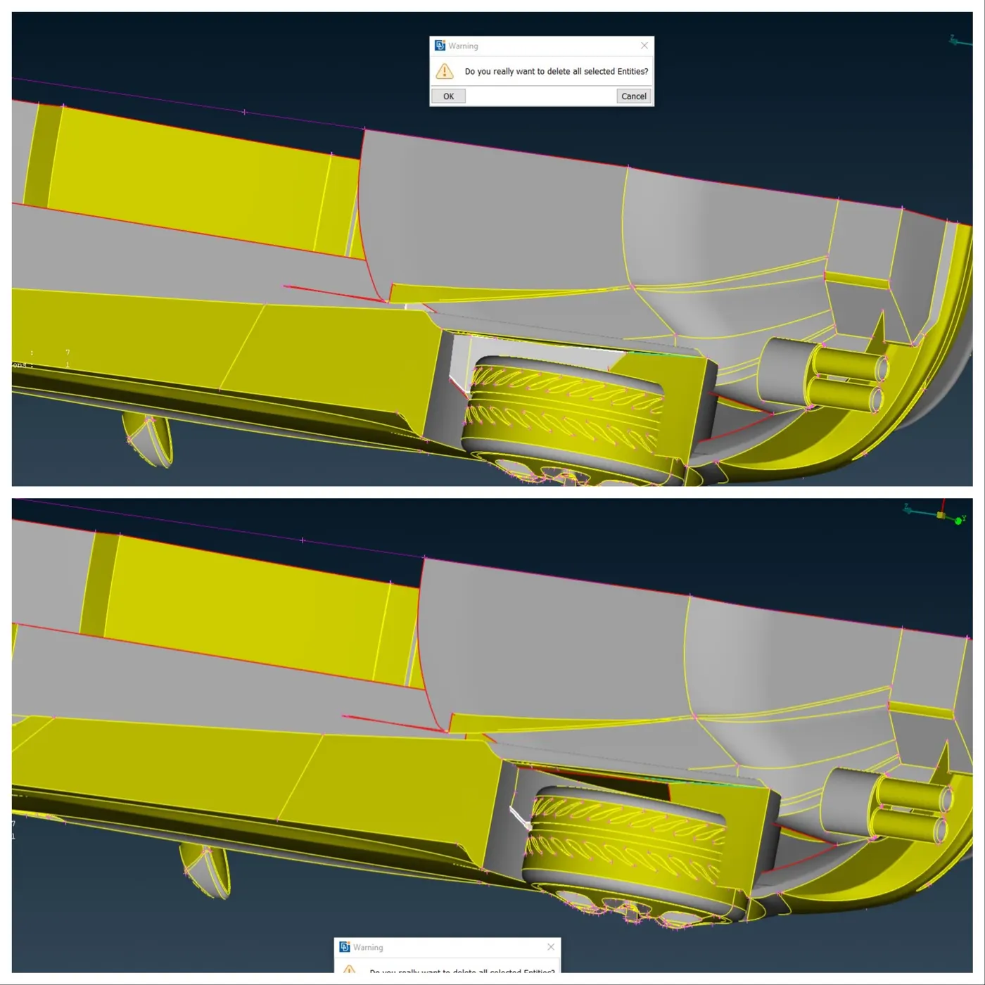
- utilities->delete option is selected.
- Select the entities to be deleted, one by one, using the left mouse-button, by a box ,PID,PID region or a polygon selection area from Feature Selection toolbar
- if necessary, deselect any of the selected entities using the right mouse-button.
- Confirm the end of entities selection with the middle mouse-button.
- As the selection is confirmed,Warning window appears ok button is selected by right-mouse click all the selected entities are deleted.
5.In this model,Headlight Whole assembly creates a separate volume inside the car ,for making the single volume inside the car deleting surfaces,procedure for Deleting the surfaces (associated with Triple CONS (or) splitting the inside volume of car) is followed for multiple times.
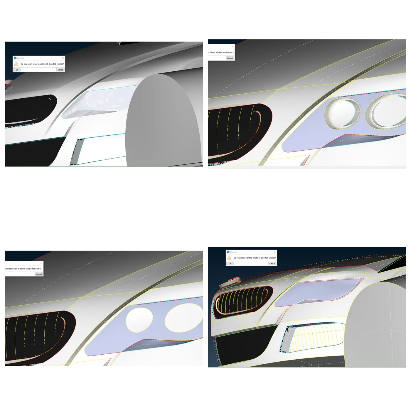
6.On Drawing styles toolbar deselected the shadow option ,this will displays a model in wireframe mode.Single CONS araised because of headlight surface and body surface is not joined . Topo->CONS->Paste then selected the CONS using entities option and scroll button is clicked.Paste CONS window appears on that ok button is clicked.
Procedure for converting Single to double CONS:
- Topo->CONS->Paste option is selected.
- Single CONS is selected by placing the mouse over it and left mouse button is clicked.
- Another Single CONS is Selected by placing the mouse over it and left mouse button is clicked.
- Mouse scroll button is clicked to end the selection.
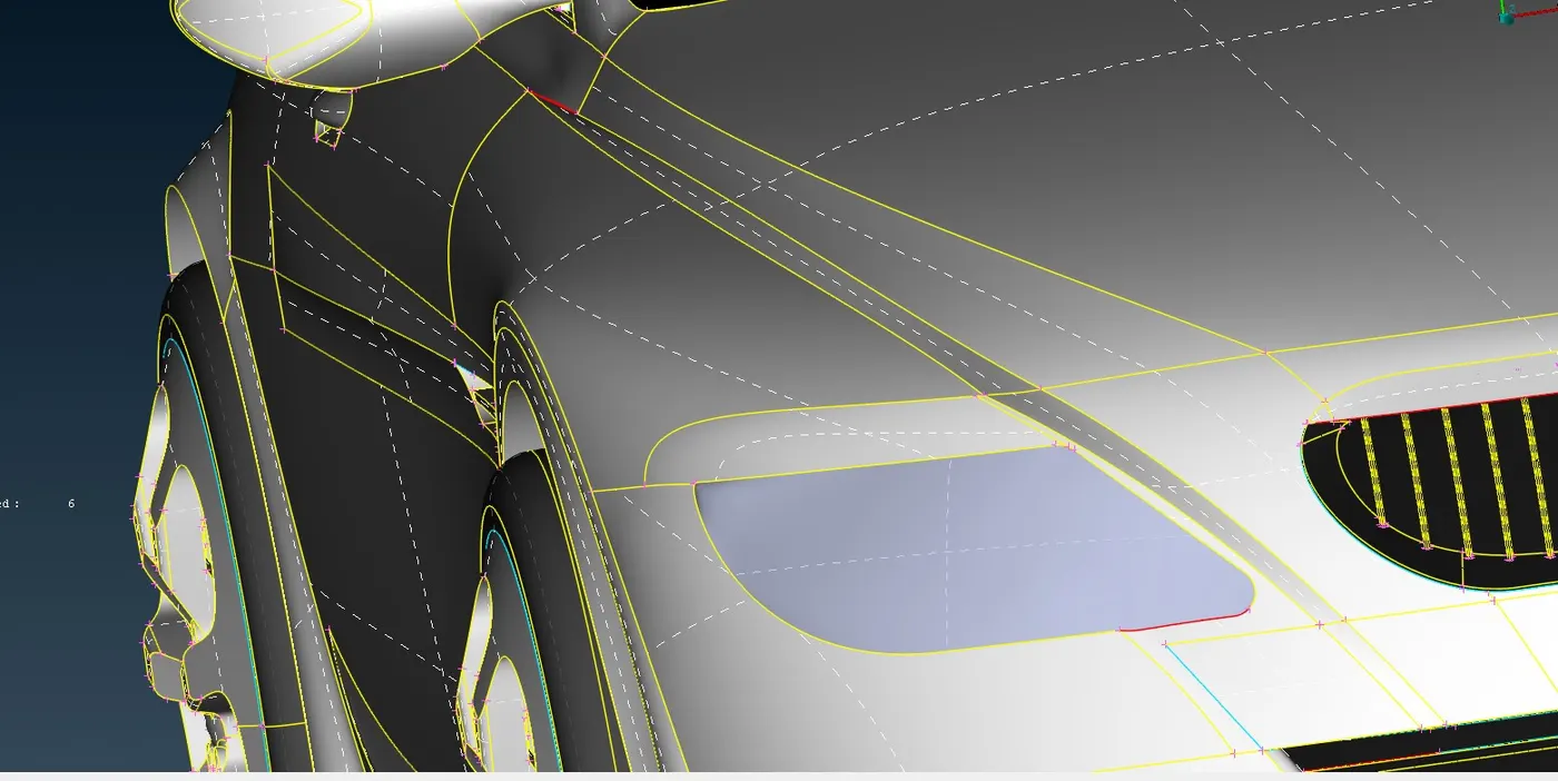
Above picture shows the location of the presence of Single CONS.
7.Presence of triple CONS below the headlight is because of protude surface present at volume inside the car.It will clearly shown on below picture.
Presence of triple CONS shown in top of the below image has a very small protuded surface
Presence of planar surfaces at the center of fins will have triple CONS
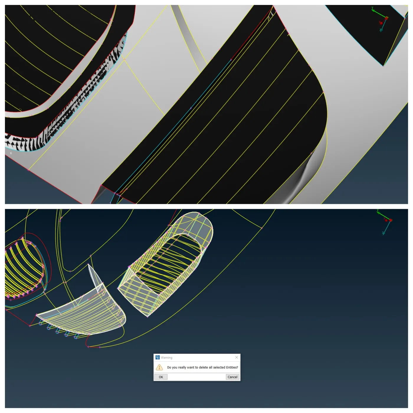
Deleted that protude surface ,planar surfaces and gliche using Deleting surface procedure described above.surface is selected by the entities option itself.
8.Presence of protuded surface will be deleted by deleting surface procedure is used.Even after deleting the surface will present a single CONS,while trying to select,it selects the whole surface.To split the surface Topo->project->CONS is used selecting the CONS and then surface is selected. This will split the surface on the bottom side,Topo->hotpoints->delete is used then selected the hotpoints .Topo->faces->Cut option is used and two hotpoints are selected.This will split the top surface.After deleing surface, procedure is used.
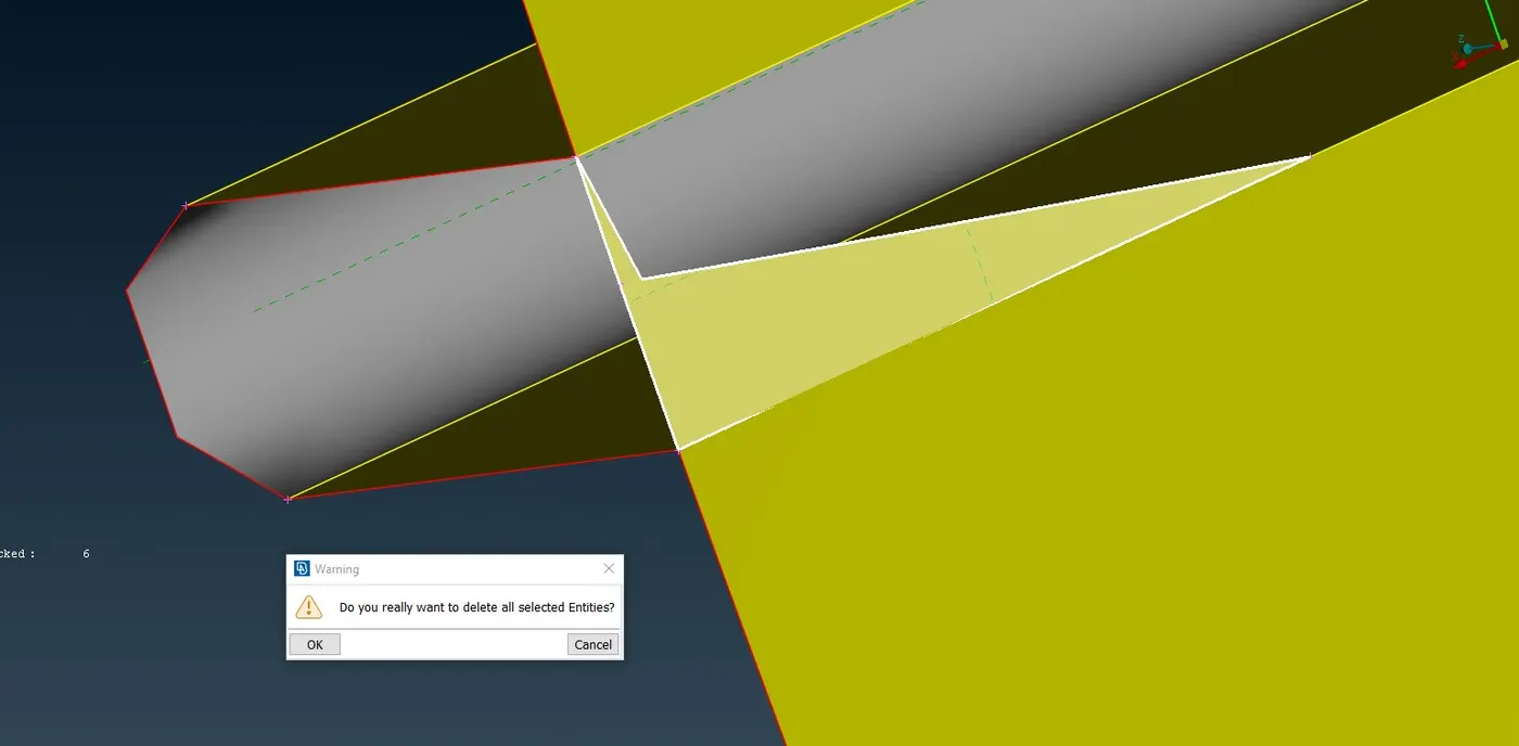
9.on the sameside remaining Fins of planar surface is deleted using deleting surface procedure.surface selected using entities option.
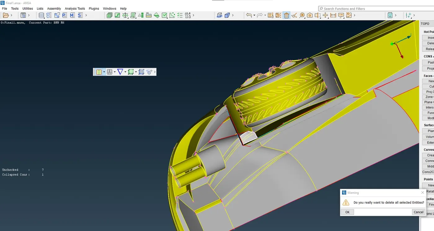
10.interface between Fins and body the plane surface is present there.due to the overlapped surfaces ,first surface is deleted using the deleting surface procedure and to avoid the difficulty in selecting face using focus->inot option these fins will be isolated by using box select of entities then scroll mouse button is clicked.then Topo->CONS->Project option is used to project the CONS on the body surface,selection of CONS with the entities option then scroll-mouse button is clicked then face is selected using an entities option then scroll-mouse button is clicked.if delete that surface using deleting surface this removes the obstacle for making into single volume.
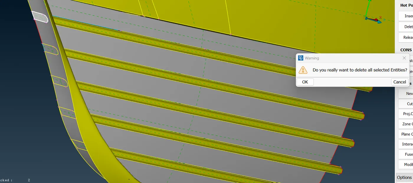
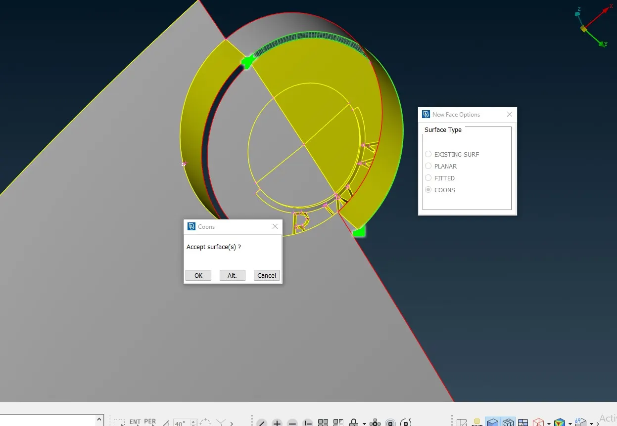
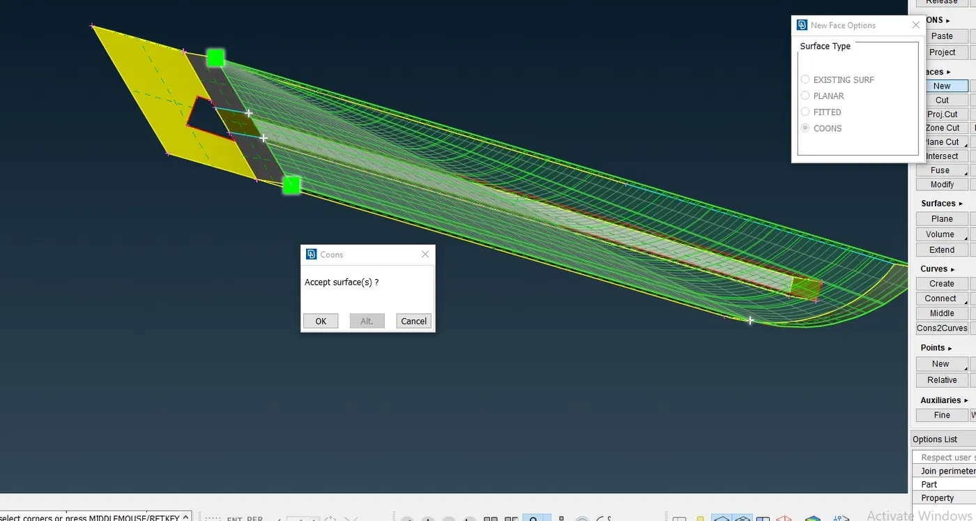
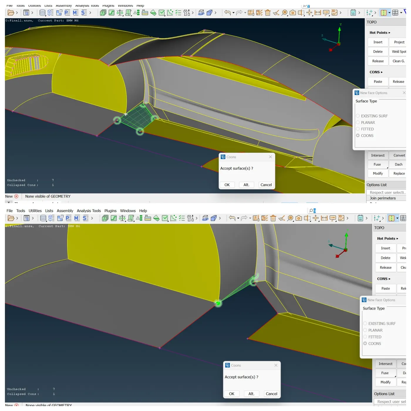
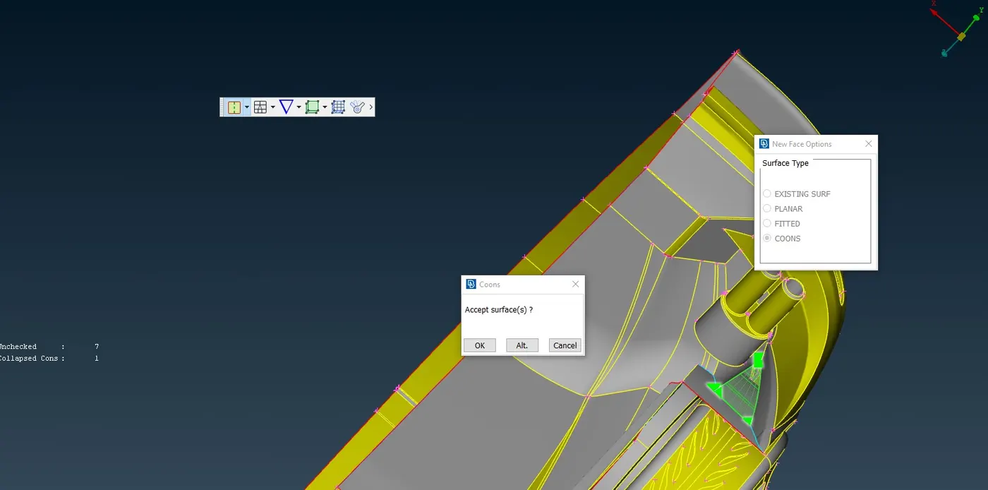
11.Deleting the surface present between the fin and body by using the Deleting surface Procedure.after this,Deleting the unmatched surface of the fin with the body and creating the new surfaces Topo->faces->new then new face options window appears COONS is selected and CONS will be selected with the help of entities option then scroll-mouse button is clicked , COONS window appears ok button is selected.
Procedure for creating New faces:
- Topo->faces->new is selected ,New face option window appears
- Different algorithms will displays.Among that one algorithm is selected.
- on feature selection shows a variety of functions to select those entities such that entities,loop,PID,PID area etc..,
- select boundaries by placing the mouse over an entity and clicking left mouse button.
- Mouse scroll button is clicked to end the selection.
- if existing surf is already selected in new face option window, then select face by placing the mouse over the surface and left mouse button is clicked.
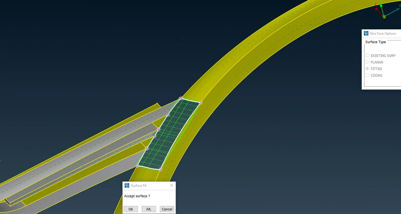
- if Planar (or) Fitted (or) COONS ,anyone of the algorithm is already selected in the new face options window,then confirmation (or)surface fit (or)COONS window appears
- it generates the set of faces for the boundaries then click alt button using right mouse button over it ,to get a needed surface
- if needed surface is displayed as preview ,then Click ok button by placing the mouse over the ok button then left-click with mouse button.
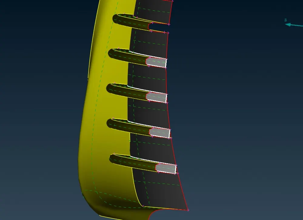
12.Topo->CONS->Project will project shape of cons on the body,Selecting the CONS by using entities option ,Scroll mouse button is clicked ,selected the face using entities option then scroll-mouse button is clicked.This will project the CONS on the selected face and split it.Then Projected CONS creates the cut surface but Spliting never formed as a chain due to that selecting the cut surface leads to selection of full face.Topo->faces->Extend option is used to join the surfaces,select the Single CONS then scroll-mouse button is clicked ,face is selected then scroll mouse button is clicked.After that deleting surface procedure is followed.Atlast we can make similar to the first fin.
Extend-This function extends Faces (source), according to a specified distance or until they reach a target Face or target group of Faces, by adding new Faces as extensions to the source ones.
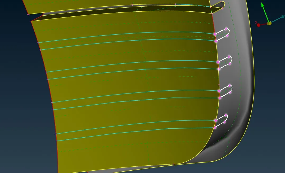
13.on the first fin slot consists of triple CONS ,that is a small surface.Deleting surface procedure would be followed.
14.images represents the single CONS down the first fin can be resolved by following procedure for converting Sigle to Double CONS.
Paste-This function pastes (joins together) two or more CONS segments that lie close to each other, and which usually are boundaries of different Faces
15.Deleting the faces using the deleting surface procedure,surfaces are selected using entities option.
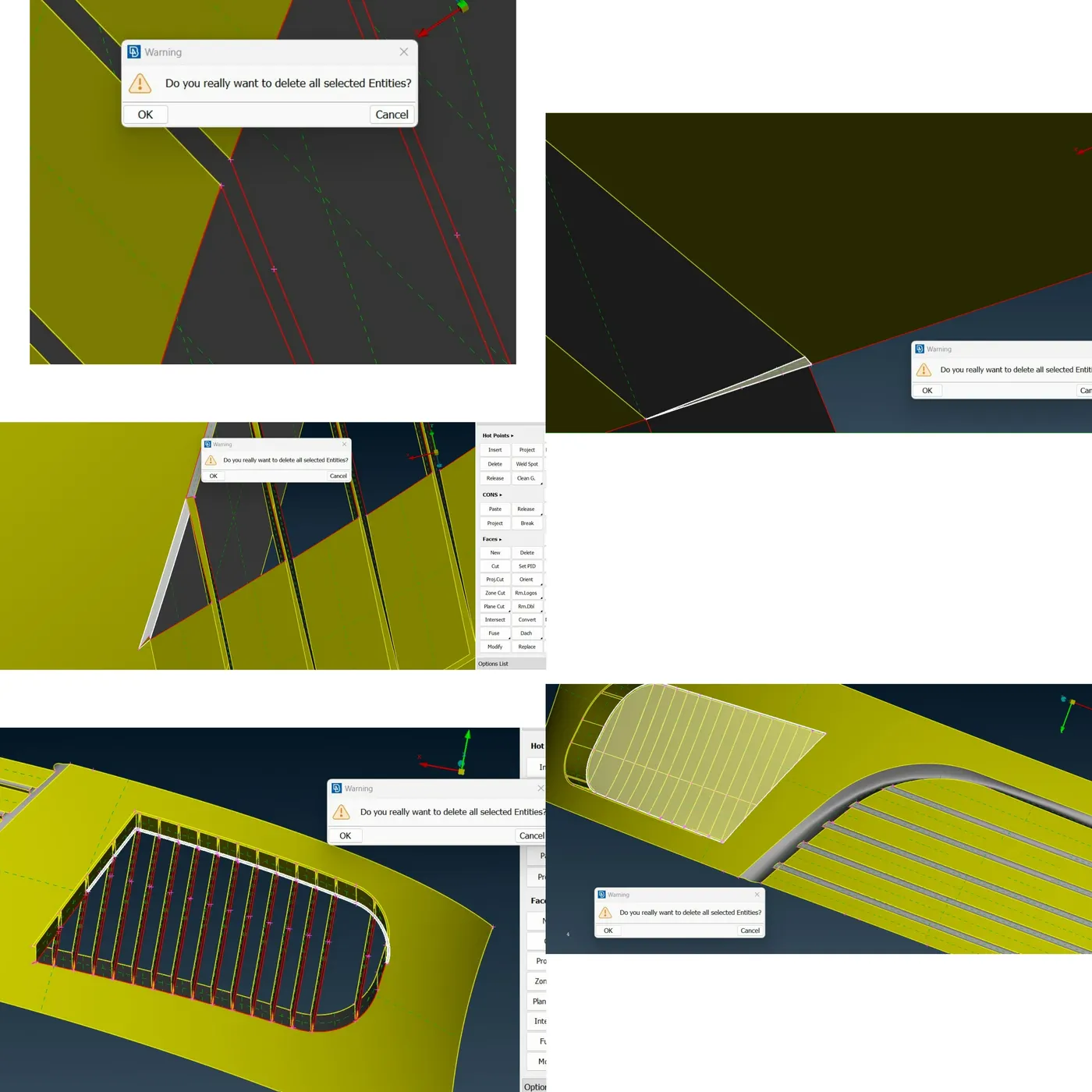
16.Creation of surface by following the procedure for creating new face, COONS is selected boundaries selected using loop option.Similarly fitted algorithm uses for several boundaries.
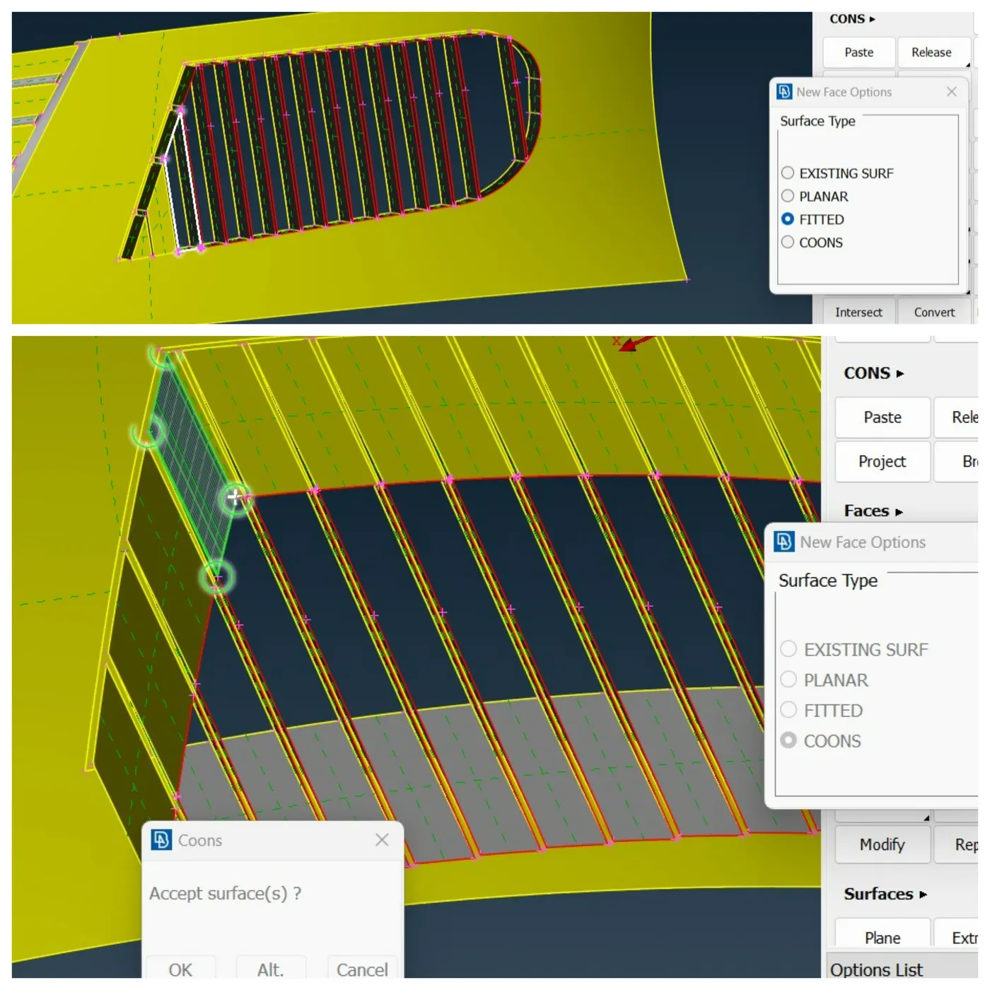
17.To split the surface ,Topo->hotpoints->parametrical option is used then parametrical input window appears distance value is entered as ~7.06 and giving the direction by selecting the boundary and then ok button (this will create the hotpoints at the mid of the selected boundary).Creation of face by following procedure of creating new faces ,three boundaries is selected then COONS algoritm is selected.
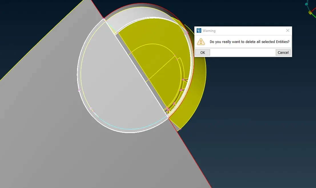
18.Cleanup on the Vehicle Logo Part.Focus->All, to display the whole model,then Focus->inot option is used and Needed entities selected using Box select.Deleting surface by following procedure.Surfaces are fully selected using entities option.
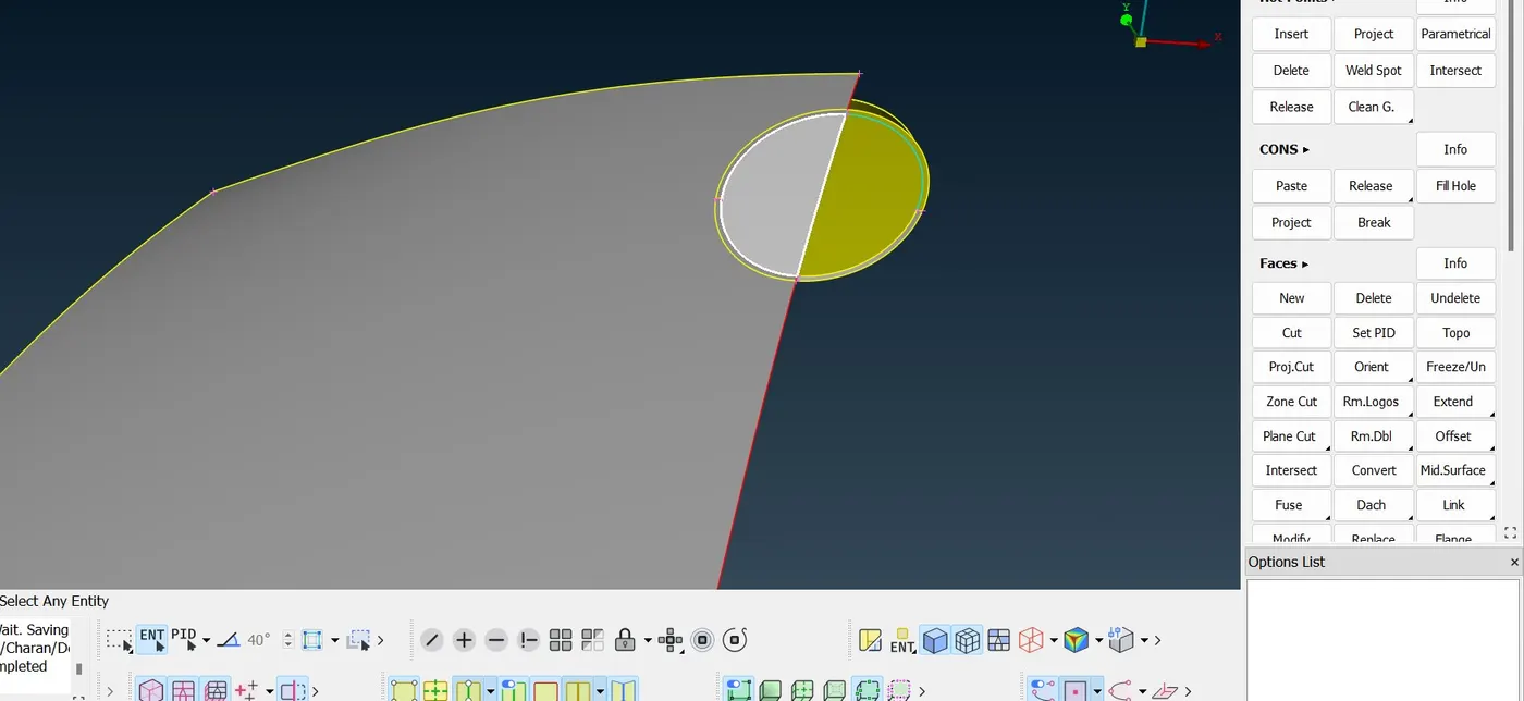
In the similar Way another half Surface is also deleted.
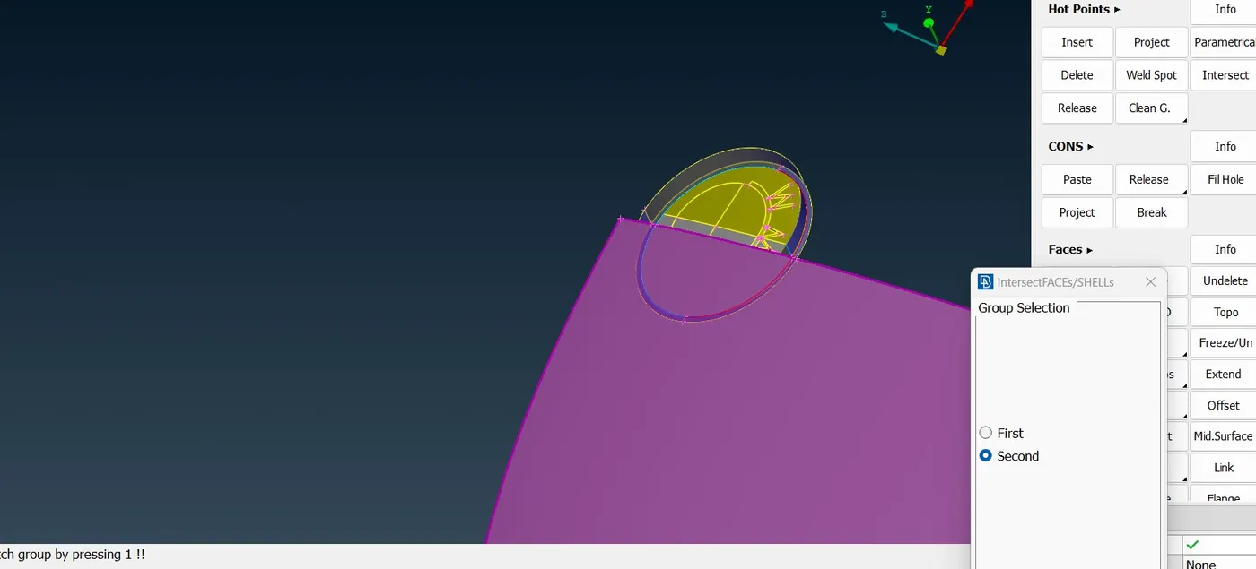
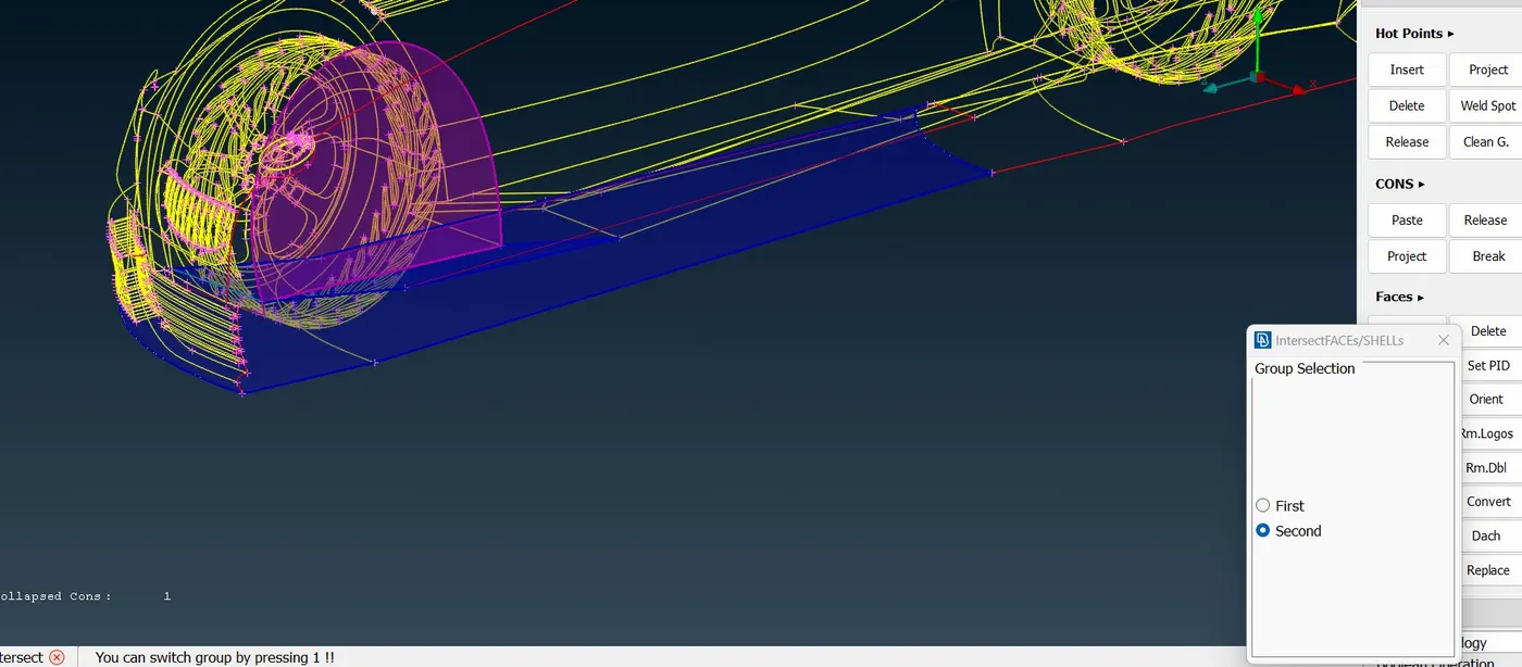
Topo->faces->Intersect option Is used ,First surface is selected using entities option then scroll button is clicked,second surface is selected used PID Region option and then scroll button is clicked.This will help us to split the surfaces and to delete it directly.Surfaces which is unrelated and small is deleted from Delete face area window appears from that selecting keep for only two surfaces for remaining three surfaces would be deleted.
Intersect-This function defines the intersection between two groups of Faces and/or FE elements that penetrate each other.
Deleting surface by following the procedure.
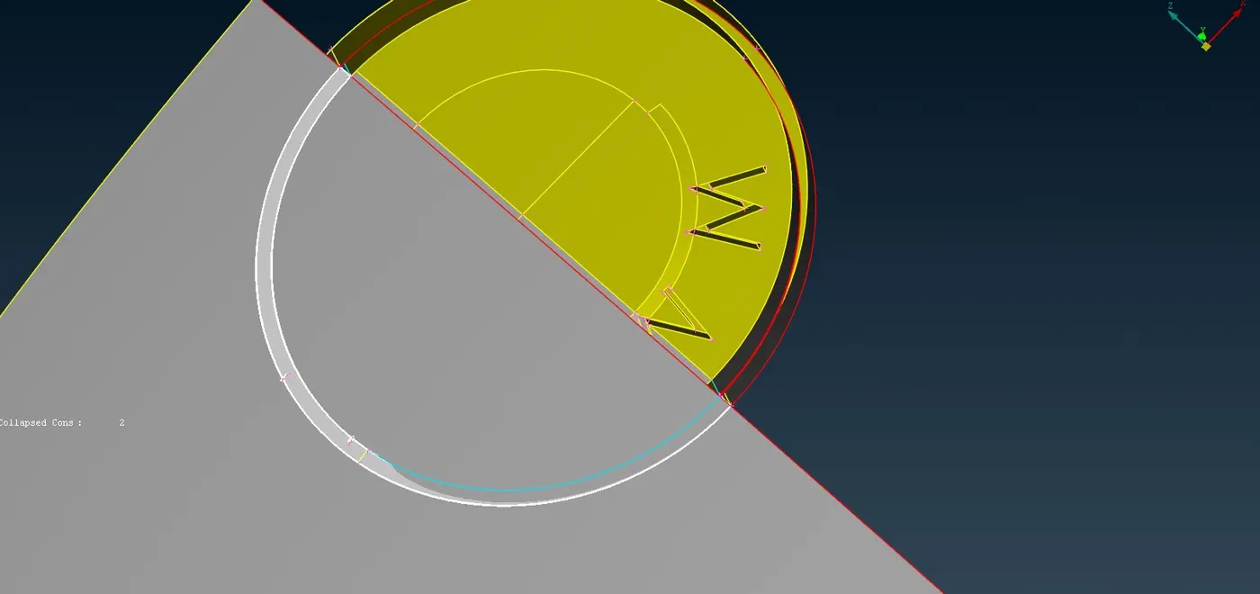
Outer surface of logo turn into the single CONS,Bonnet surface is splitted Topo->Faces->Extend is selected then red CONS is selected then the face is also selected.Deleting surface by following the procedure.
Creation of new surface by following procedure for creating new faces, then COONS is selected then the boundaries is selected using entities option then shell property help window appears on for this surface creation, but selecting the PID model this automatically selected PID then mouse scroll button is clicked.this would be repeated for another half for creation of surface.
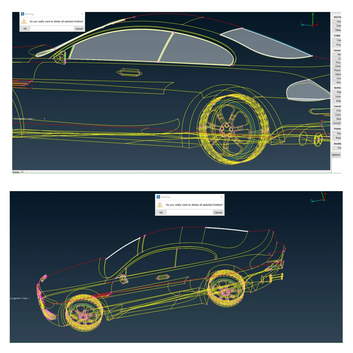
<!-- [if !supportLists]-->19. <!--[endif]-->Deleting surfaces at the winshield, door mirrors ,brake light etc to remove triple CONS by following the procedure.
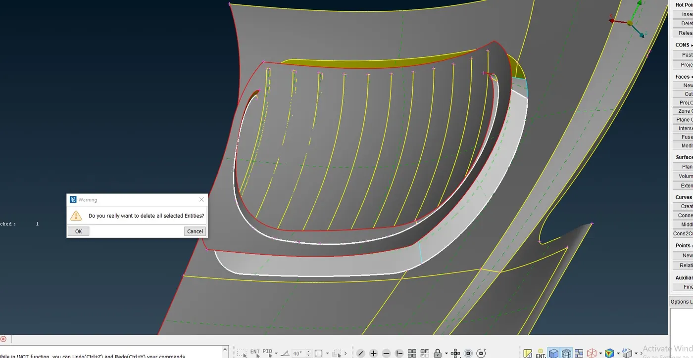
<!-- [if !supportLists]-->20. <!--[endif]-->Deleting Surface by following procedure at the center grills to change the triple CONS to the Double CONS
Projecting the CONS by Topo->CONS->Project option ,selected the CONS then Selected the surface using an entities option then scroll-button is clicked.
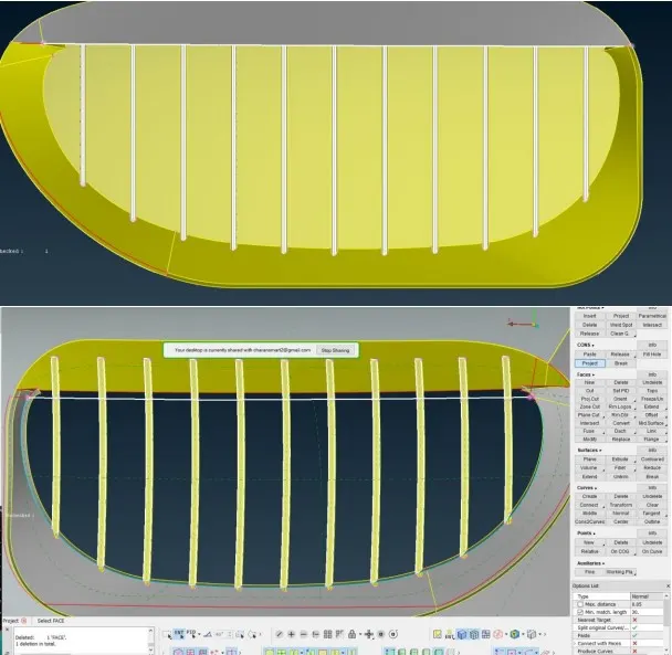
Project Cut - This function is used to cut (split) a Face by combining the Hot Points>Project and Faces>Cut functions. In other words, it splits a face between a selected hot point and its projection on a selected CONS
Topo->faces->Project cut option is used,selecting the hotpoints ,selecting the CONS then scroll-mouse button is clicked .this would be used at splitting the grills on the slanted and vertical surfaces.
Topo->faces->cut option is used,selected the two hot points .this procedure used for cutting the surface backside of grill
Topo->faces->Project cut option is used,selecting the hotpoints ,selecting the CONS then scroll-mouse button is clicked.this procedure is used to join the CONS to the edge of the surface.
Topo->faces->Extend option is used,selected the Single CONS then scroll-mouse button is clicked,selected the face using scroll-mouse button is clicked,Single CONS edge has extended upto the surface .
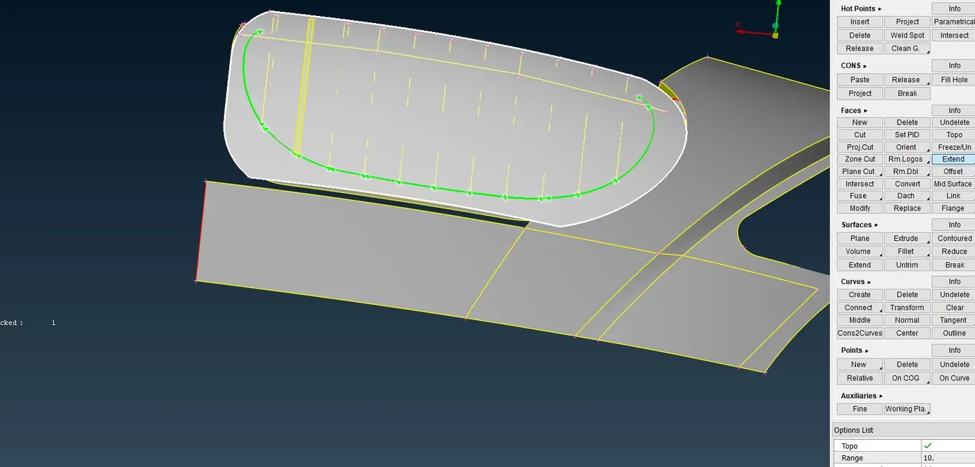
Topo->faces->proj cut option is used ,selected the hotpoint scroll mouse buttton is clicked,selected single CONS at the edge scroll mouse button is clicked .This will deletes the surfaces.
Deleting the surface that has only single CONS.
Deleting the Splitted grills by the using the procedure,surfaces is selected using box select
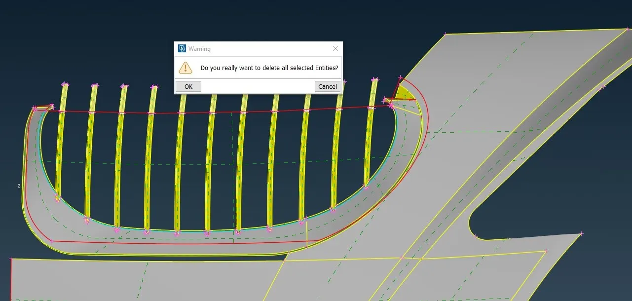
Deleting the surface by following the procedure at the backside of the grill
Creation of faces by following the procedure for creating new faces, COONS algorithm is selected,selection of boundaries using entities option .Multiple time this procedure is repeated.
Topo->CONS->fill hole also used,selection of boundaries with one left mouse click ,scroll center button is clicked.This procedure is also used for creation of surfaces where four edges act as the boundaries.
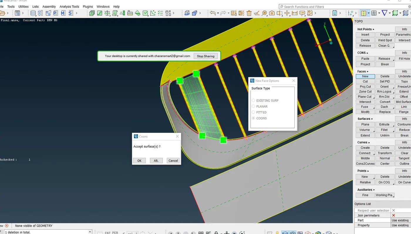
At the edges to topo->faces->cut option is used,selected the hotpoints to cut the surfaces .Deleting surface by following procedure is carried at both sides
Topo->faces->new ,new face options window appears COONS algorithm is selected ,boundaries selected scroll-mouse button is clicked,COONS window appears clicked ok button.
21.Focus -> inot option is used then selected the surfaces using box select.
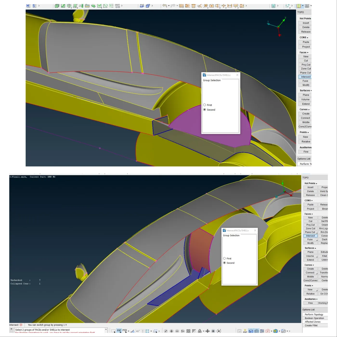
Intersection of faces would create at intersection surfaces.Topo->faces->intersect option is used.intersect faces window appears then selected the first then surface is selected using PID region then scroll-mouse button is clicked then surface is selected using PID region then middle scroll mouse button is clicked.
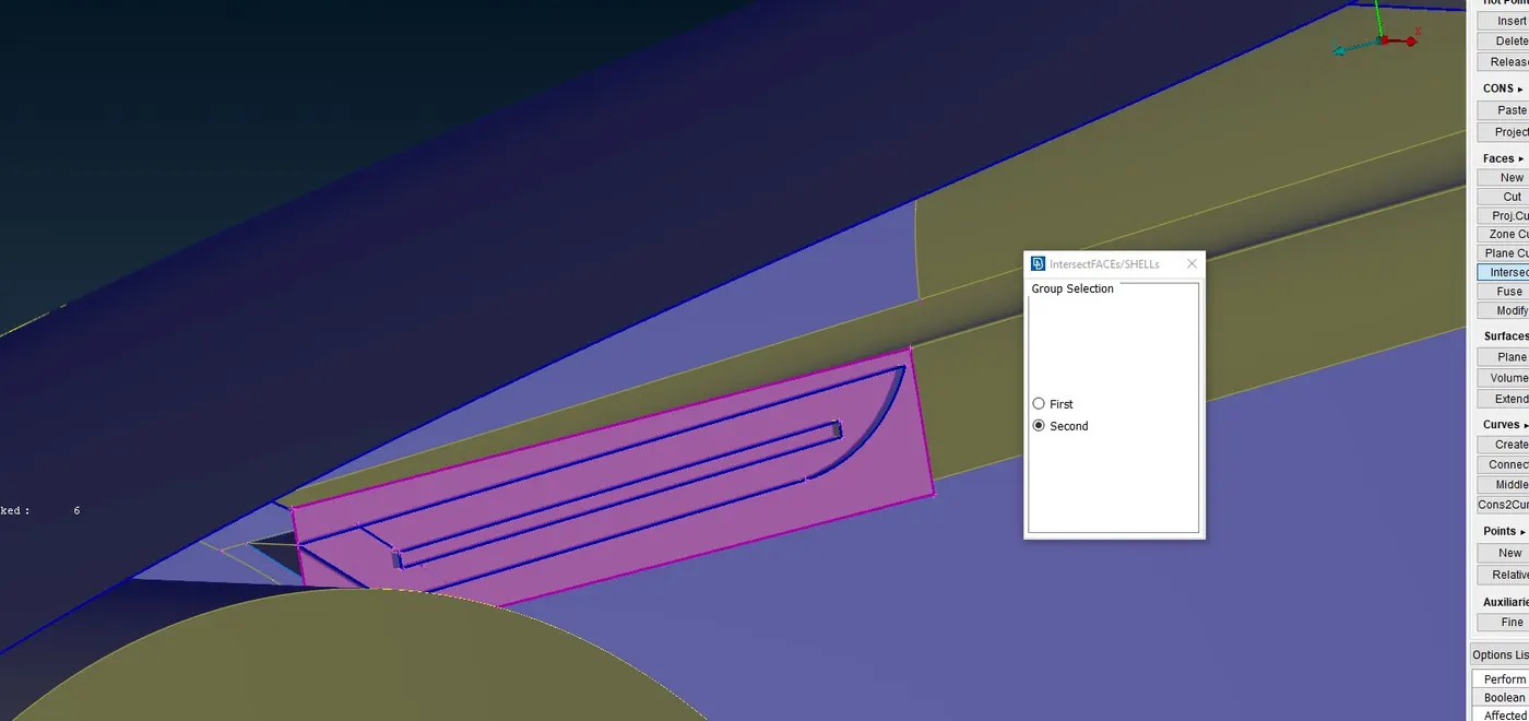
Deleting the surface by following the described procedure.
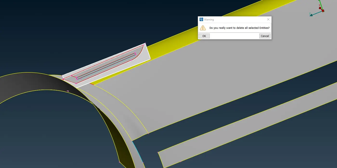
Topo->faces->extend option is used then hot points is selected then scroll mouse is clicked then faces is selected then scroll mouse button is clicked.Deleting the surface is followed by procedure
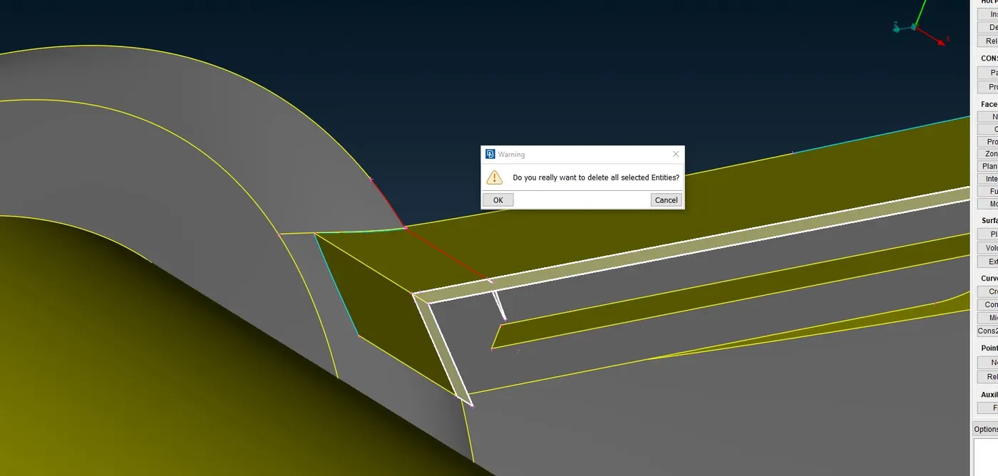
Creation of surface by following the procedure for creating new surface.Boundary is selected by using loop option.new face options window appears then COONS algorithm is used.
Topo->faces->extend option is used then selected the Single CONS then middle scroll mouse button is clicked then face is selected then middle scroll mouse button is clicked.this is for converting the Single CONS to Triple CONS
procedure for creating new faces is followed ,then COONS is selected then the boundaries is selected.
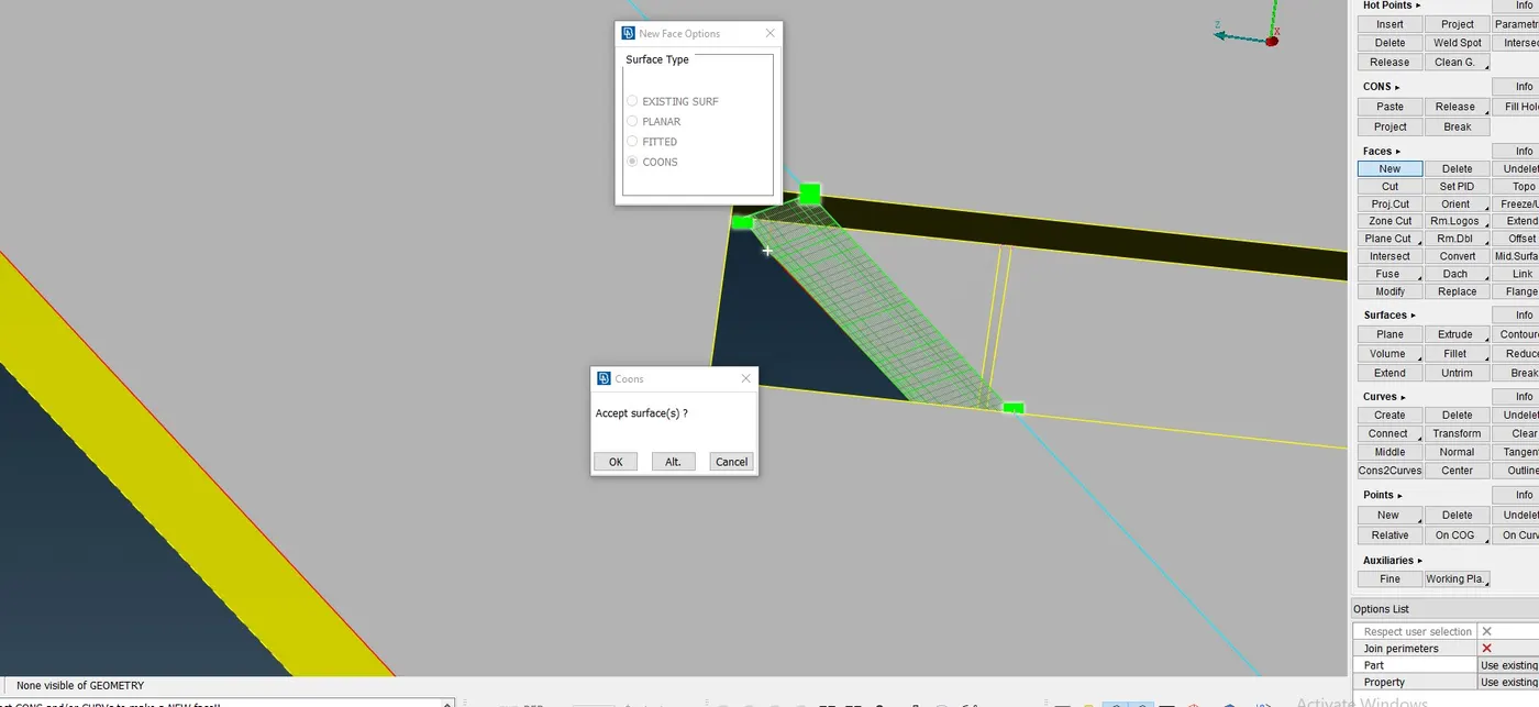
Deleting the surface over the previously created surfaces.
Creation of surfaces by following procedure for creating new faces,then COONS is selected then boundary is selected.
Deleting the surface by following the described procedure.
Created the surfaces by following procedure for creating new faces. Boundaries is selected then COONS is selected.
Deleting surfaces in the described procedure.
Extended the surfaces at mirror attachment location.
Due to the single CONS Surfaces would be deleted by following the procedure then creation of new faces by following procedure for creating new faces then COONS is selected then boundary is selected.
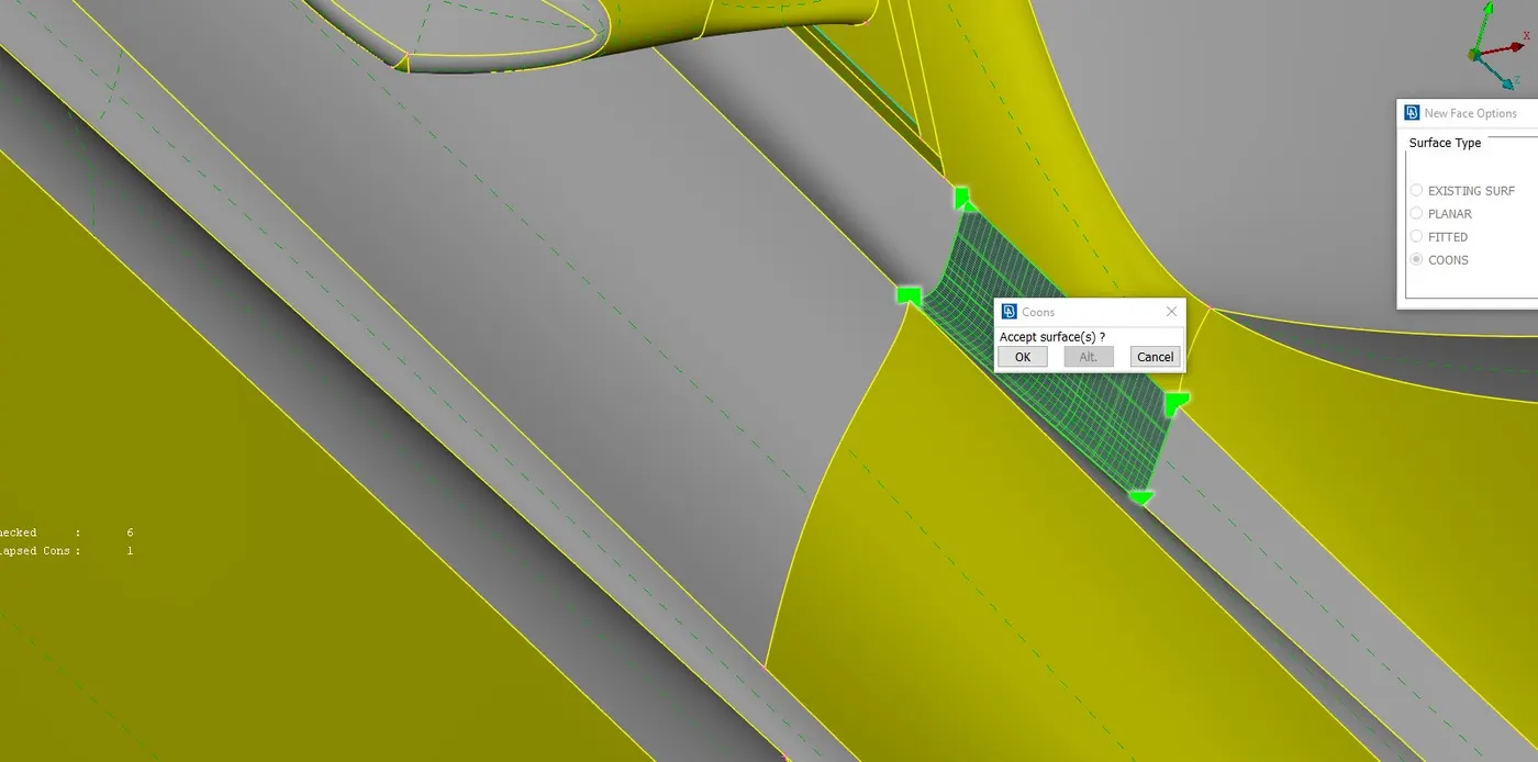
<!-- [if !supportLists]-->22. <!--[endif]-->Deleting the surface by following the procedure as decribed before.(This will convert the triple CONS to Double CONS and then convert the single CONS to Double CONS ).selecting the surfaces using entities option.
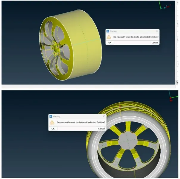
Creation of surface by using topo->faces->new option is used.New face options window appears then COONS algorithm is selected.
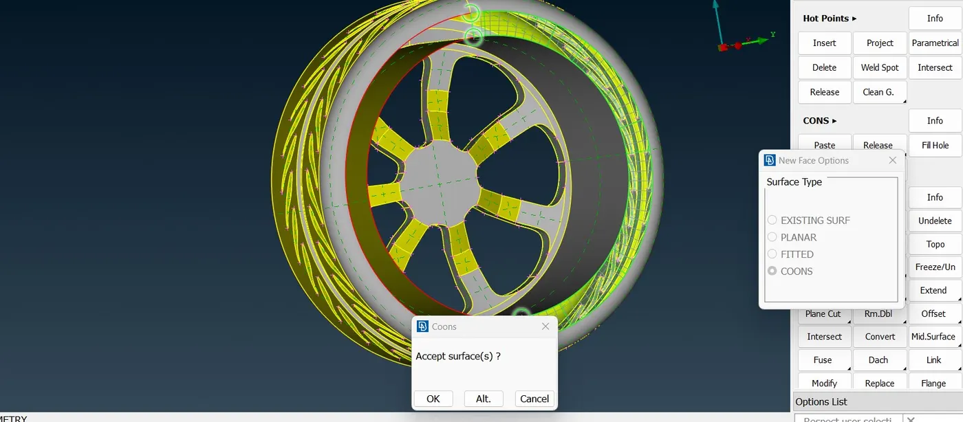
Front tyre geometry cleanup is done.in the same way back tyre geometry cleanup is done.
Deleting the surface by following the described procedure.
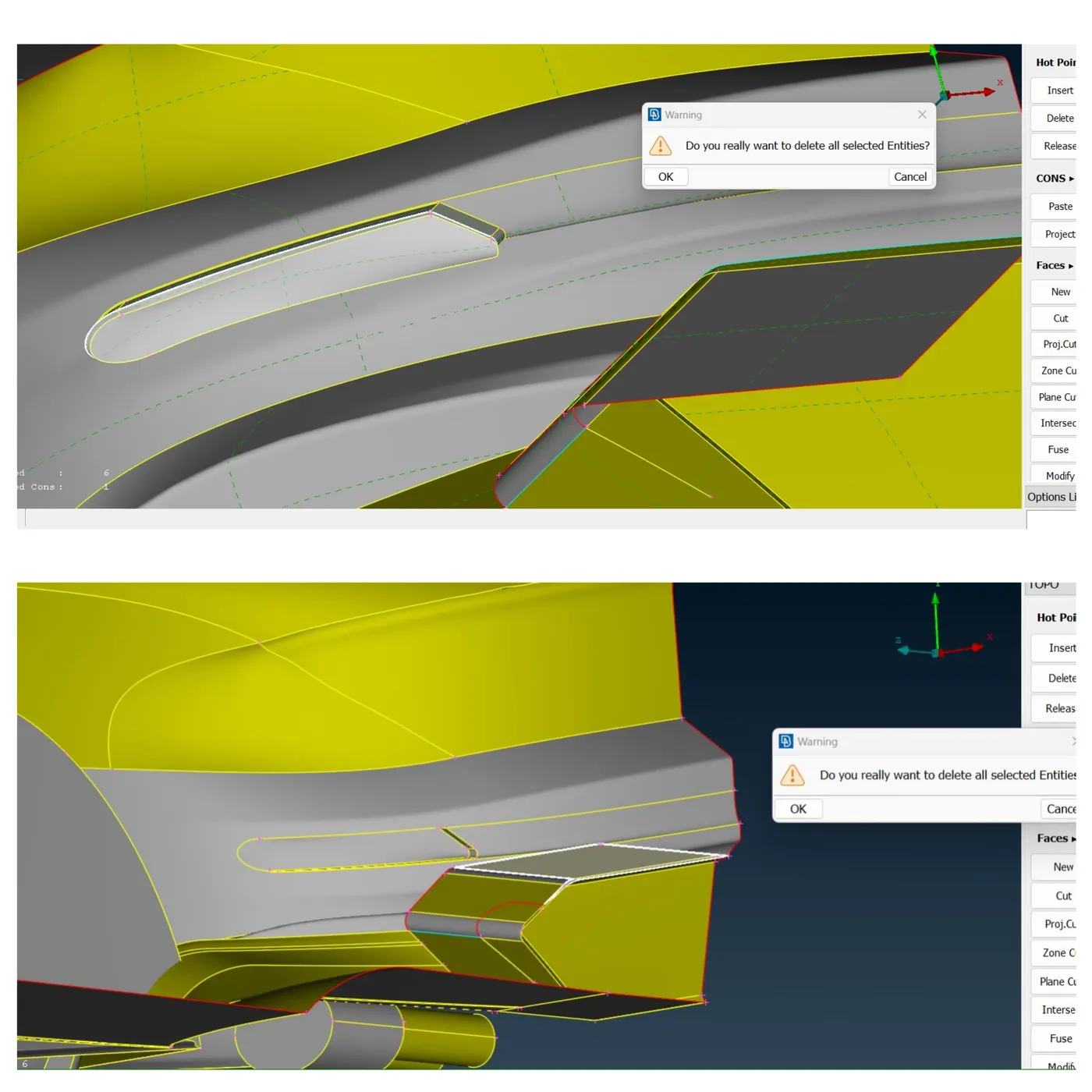
Topo->faces->extend option is used then selected single CONS then middle scroll button is clicked then face is selected then middle scroll button is clicked.Deleting the surfaces by following the procedure.
Creation of the surface using topo->faces->new option is used.New face options window appears then COONS is selected then boundary is selected using entities option then scroll mouse button is clicked.
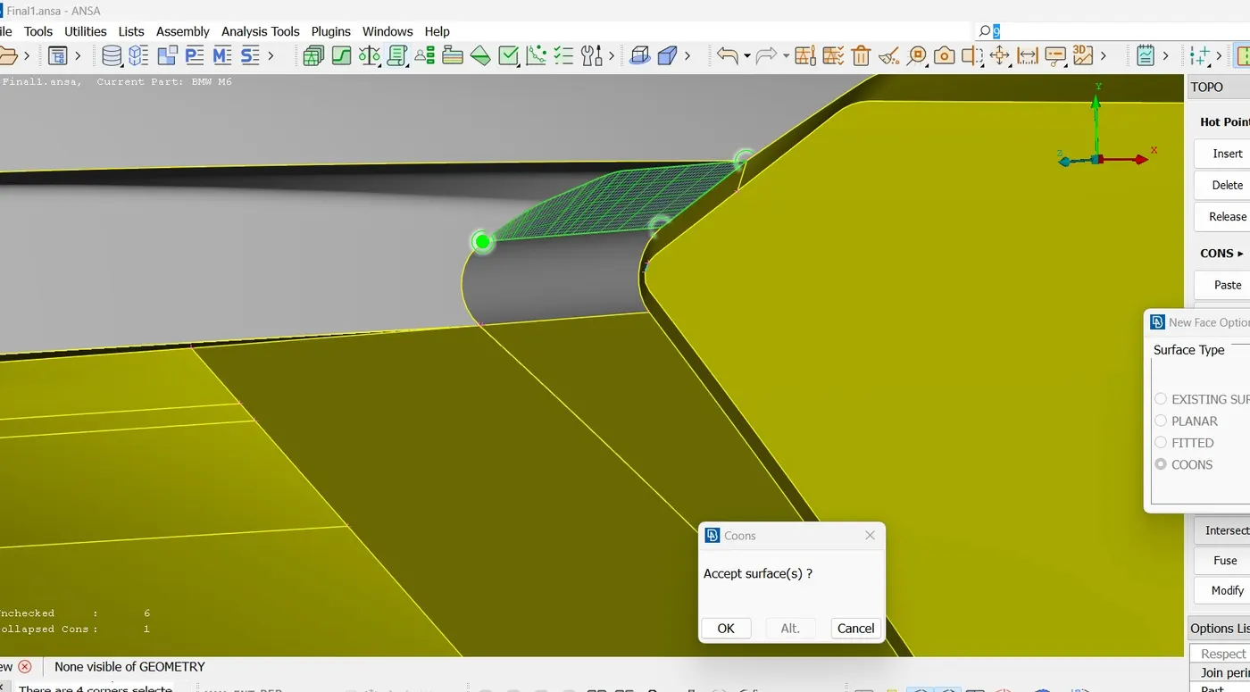
Topo->faces->intersect option is used,intersect faces window appears first is selected then surfaces is selected using entities option and then scroll mouse button is clicked then second surfaces selected using entities option then scroll mouse button is clicked.
Topo->Curves->Delete option is used then the Curves are selected then scroll - mouse button is clicked.
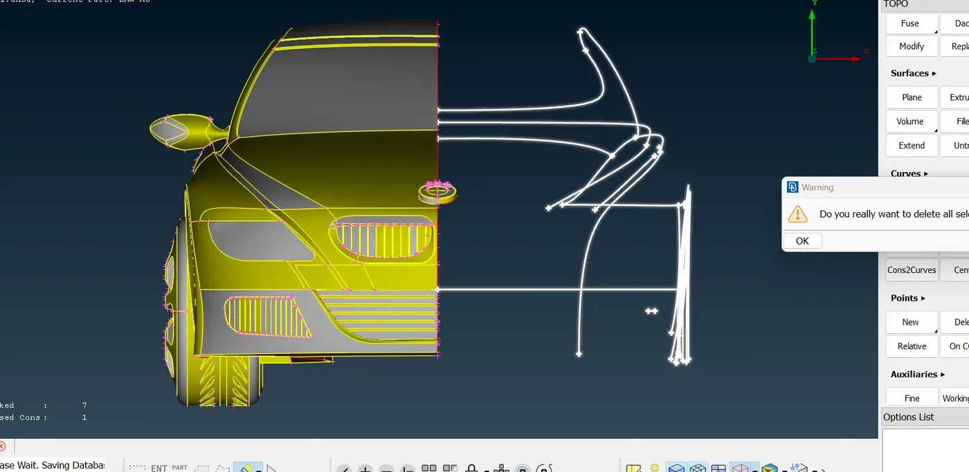
Topo->Curves->Cons2Curves option is used then CONS is selected then Scroll mouse button is clicked.
Deleting the surfaces by following the procedure
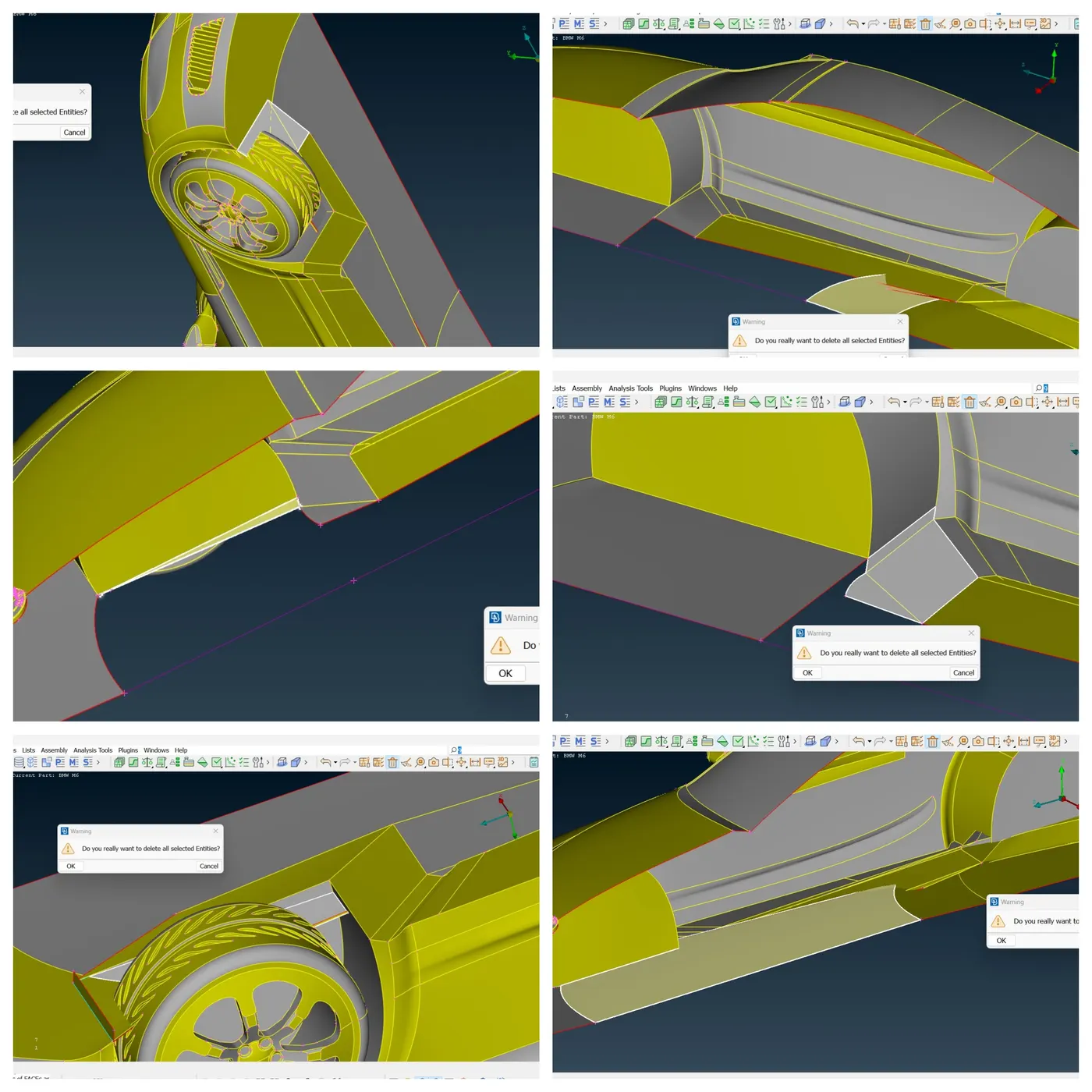
Topo->Faces->Cut option is used then the created the hotpoints .Deleting the surfaces by following the procedure
By following procedure for creating new faces ,then COONS is selected then boundaries is selected.
<!-- [if !supportLists]-->23. <!--[endif]-->Topo->faces->intersect option is used then intersection faces window appears then first is selected then surfaces is selected then mouse scroll button is clicked then second surfaces is also selected then scroll mouse button is clicked.
Deleting the surface by following the procedure
Topo->faces->intersect option is used ,Intersection faces window appears then first surfaces is selected then mouse scroll button is clicked then second surfaces is selected then mouse scroll button is clicked.
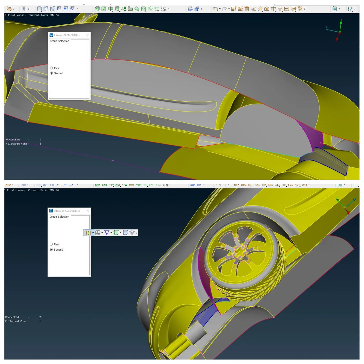
Deleting the surfaces by following the procedure.
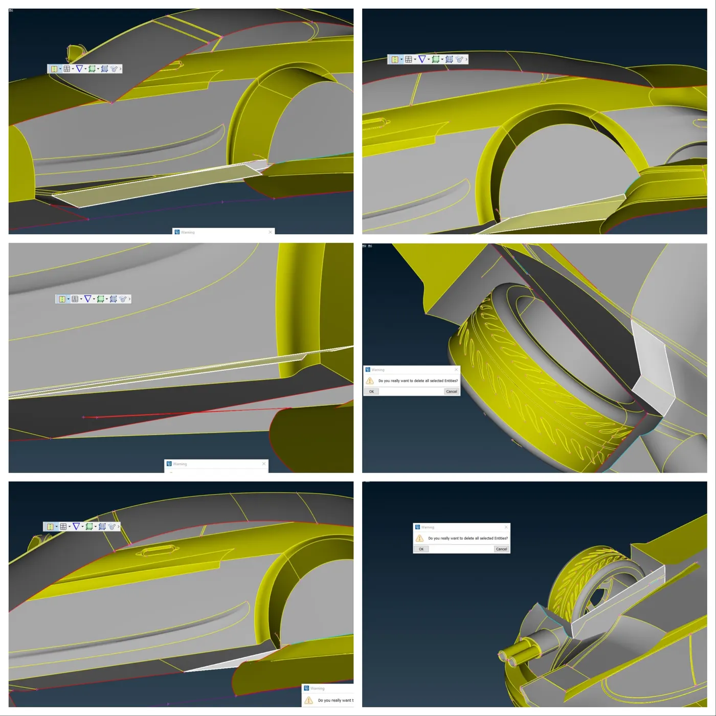
Creating the surface by following procedure for creating new faces ,then COONS is selected then Boundary is selected.
Topo->faces->Extend option is used then selecting the single CONS then mouse scroll button is clicked then face is selected then mouse scroll button is clicked.
Deleting the surfaces by following the procedure
Creation of surfaces by following procedure for creating new faces,then COONS is selected then boundaries is selected .
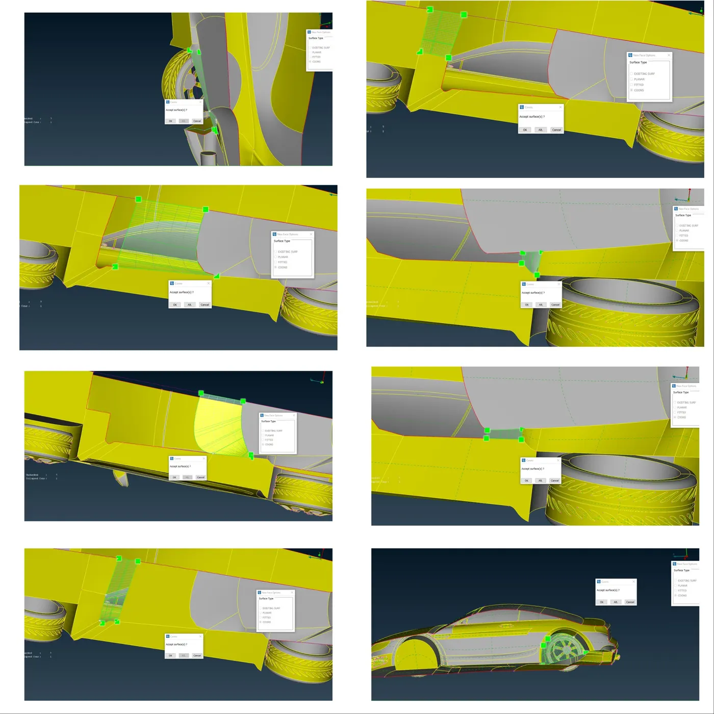
If needed topo->hotpoints->insert option is used then selecting the location of CONS or Curves.topo->hotpoints->project option is used then selecting the nodes then mouse scroll button is clicked then selection of curves or CONS then mouse scroll button is clicked.This is mostly used for splitting.
Unchecked CONS appeared on the screen Right click show only has solved by deleting surfaces (or ) topo->CONS->Paste (or )topo->CONS->Release has used to solve that.
Tools->Checks->Geometry option is used then checks manager window will appear then execute
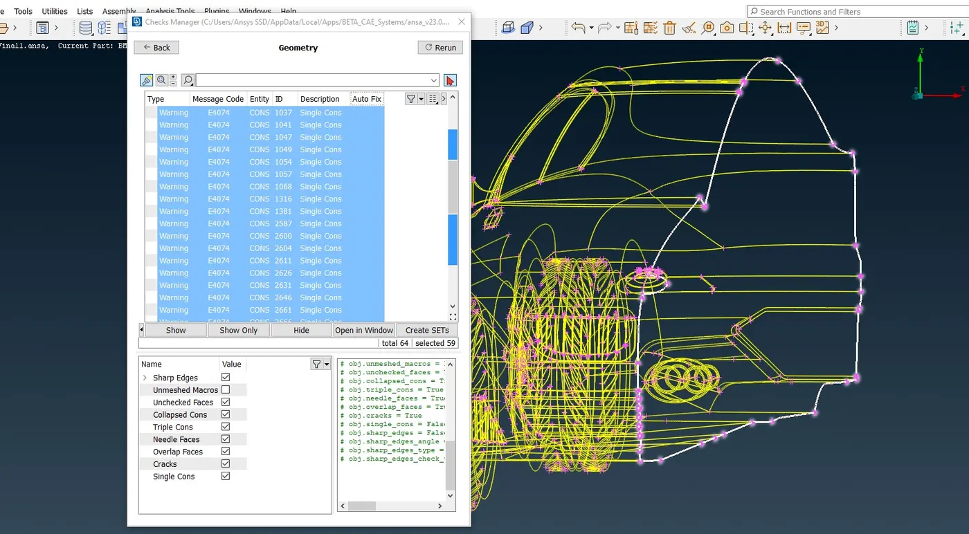
Triple CONS present in the checkmanager is solved by the topo->CONS->Release and Topo -> faces->Topo option on the particular boundary.
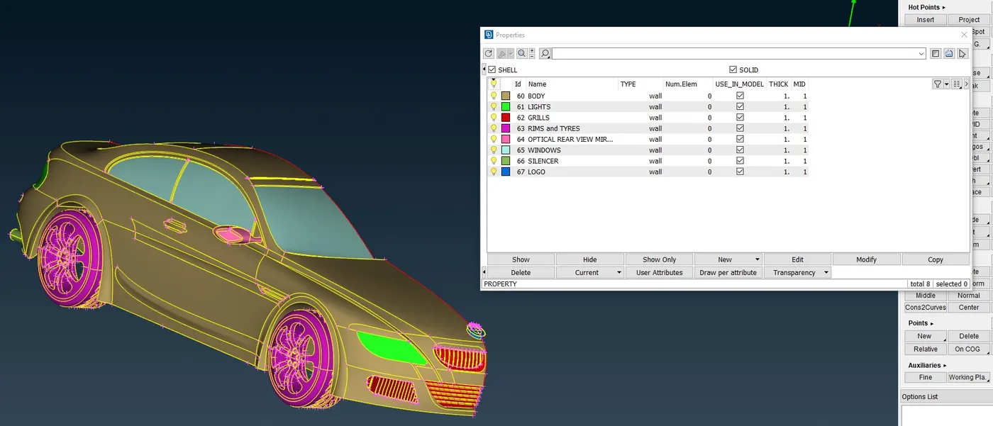
<!-- [if !supportLists]-->24. <!--[endif]-->Creation of PIDS Lists->properties option is used.Properties window appears then right-click then select new option then select shell property then property window appears entering the name and then click ok button.This would be repeated for another 7 times
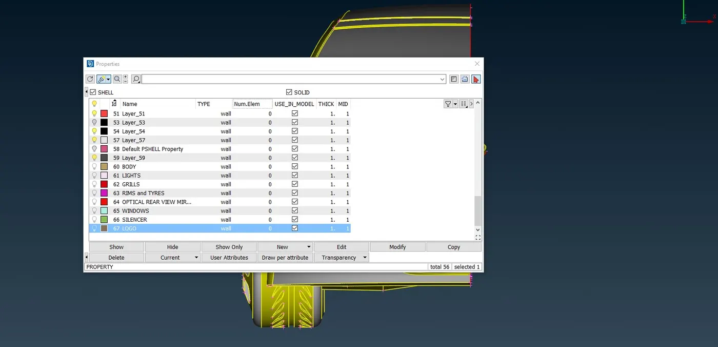
Focus->inot option is used then selected the surfaces using PID Region for isolating surfaces as per created PID Name.Then Right-click on the properties window then select apply option then selecting the surfaces by box select then mouse scroll button is clicked.this is also repeated for another 7 times
Utilities->compress option is used then compress window appears then click ok button .
Compress-This function is used to compress an ANSA database. Compression may be selectively applied either on geometric entities only (faces, curves 3D-points) or on the entire database.
<!-- [if !supportLists]-->25. <!--[endif]-->Checking for the small surface because while meshing if we choose the target length less than those dimensions will have a issues.To avoid that founded small surfaces on the PID ,Topo->faces->cut option is used and selecting the boundary then right click (or)Topo->faces->cut option is used then splitting the boundaries by creating the hotpoints then selecting the boundaries and right-click.
Especially Logo needs a cleanup because of very small surfaces present in wordings .Some Surfaces deleted by following the procedure and topo ->hotpoints->delete option is used by selecting points and creation of surfaces topo->faces->new option is used then boundaries is selected then mouse scroll button is clicked then COONS window appears then click ok button.
26.Change the module from Topo to Mesh by selecting modules->Mesh .
Meshing should started with small area PIDs.Isolating the PIDs by Lists->Properties option is selected then Properties window appears then deselect the all visiblity icon.
Then select the particular PID’s visibility icon on the properties window.then hide it by clicking scroll button on the properties tab.
Utilities->Quality Criteria is selected then Quality Criteria presentation parameters window appears then clicking Edit criteria visiblity ,Edit criteria visiblity window appears,Deselecting the all parameters then selected the required quality criteria parameters by selecting the checkbox ,click ok button.Entering the min and Max length for all PIDS ,apply button is selected then click ok button.Min and max length presented on the table below
Utilities->mesh parameters option is selected then Mesh parameters window appears,maximum length and minimum length under the shell tab value is entered.this will change for each and every PIDS
|
S.no |
PID |
Maximum length in mm |
Minimum length in mm |
|
1 |
Logo |
0.4 |
2 |
|
2 |
Grills |
0.3 |
2 |
|
3 |
Window |
1 |
3 |
|
4 |
Lights |
3 |
5 |
|
5 |
Rims and tyres |
1 |
3 |
|
6 |
Silencer |
1 |
5 |
|
7 |
Body |
1 |
5 |
Mesh->Perimeters->Length option is selected,Selection window appears either perimeter or macros would be selected.Perimeter is selected for everything then scroll button is clicked,Length parameters window appears then Length value is entered ,click Ok button.
|
S.no |
PID |
Length in mm |
|
1 |
Logo |
1 |
|
2 |
Grills |
1 |
|
3 |
Window |
2 |
|
4 |
Lights |
4 |
|
5 |
Rims and tyres |
2 |
|
6 |
Silencer |
3 |
|
7 |
Body |
3 |
Mesh->Mesh Generation->Spot Mesh->Visible option is selected
After meshing,Drawing styles->Hidden is selected,Drawing styles->Drawing Mode [ENT] is selected ,to view the Quality of the meshing
Off elements will display on screen .To reduce the off elements ,Mesh->Shell mesh->Reconstruct->visible option is selected ,Reconstruct-edit parameters window appears then select Go to next page option is clicked,Reconstruct-preview window appears ,Finish button is clicked.
If still Off elements exist,right-click on the off displayed position ,pop-up menu appears improve is selected,this improve option will selects only distorted elements ,Improve-select window appears on that by default reshape is selected ,click on Go to next page ,Click on the finish button
If still off elements exist,modules->Topo->faces->cut option is selected,Right-click the Double CONS [To delete the nearer Double CONS i.e..,surface will be present between the double CONS] [or] Modules->mesh->Grids->Move option is used,move grids window appears select free tab ,select the Node [this node will connect the surrounded elements ,by moving node will change the area of all surrounding elements],moving the mouse will change area if quality issues disappears then click mouse scroll button [or] modules->Mesh->Elements->Delete option is selected then element is selected then Delete element window appears then delete button is clicked and modules->mesh->Elements->new option is selected then new element window appears edges is selected ,on results TRIA is selected then Create button is clicked [or] Modules->Mesh->Elements->Split option is selected then split cases window appears then edges is selected then mouse scroll button is clicked.
For Each and every PID,Meshing procedure repeated from quality criteria.
Instead of spotmesh->visible,spotmesh->select option is selected. Body PID will selected,interface perimeter segments between body and other PIDs are deselected.
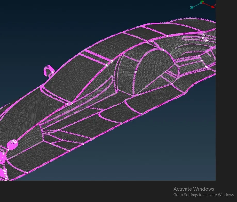
27. <!--[endif]-->Utilities->Transform->copy option is selected then selection window appears Entities is selected then all PIDs except logo PID are selected then move entities window appears then symmetry tab is selected then used a mirror 3 points plane then points are selected on the model [to create a symmetry plane] then mouse scroll button is clicked [preview the created symmetry part]then finish button is clicked.
Transform-This function is used to Translate, Rotate, Transform, Scale, Symmetry or Mirror selected entities (Faces, Points, Elements etc).
28. <!--[endif]-->Single CONS is removed by CONS->paste option is selected and Tools->checks->geometry option is selected and execute button is clicked.
29. <!--[endif]-->To create the wind tunnel,modules->topo->points->relatives option is selected then Relative points window appears then select nodes then scroll button is clicked then Relative window appears then new point cordinates[relative with selected nodes] value is entered and click ok button.
Relative-This function defines new 3D-points that lie on a given relative position from a number of selected 3D-points, Hot Points, Weld Points etc.
This procedure would be carried out another 4 times
|
Relative to the |
Direction |
Distance from reference point to the new point |
|
|
1st point |
Hotpoint present on the model |
-dy |
75 |
|
2nd point |
1st point |
dz |
5854 |
|
3rd point |
1st point |
-dz |
8411 |
|
4th point & 5th Point |
2nd & 3rd point |
dx |
1300 |
|
6th point & 7th point |
2nd & 3rd point |
-dx |
1300 |
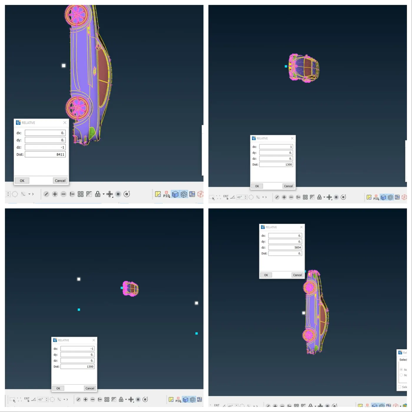
Then modules->topo->curves->create is selected then curves is created by selecting the points ,as the plane surface
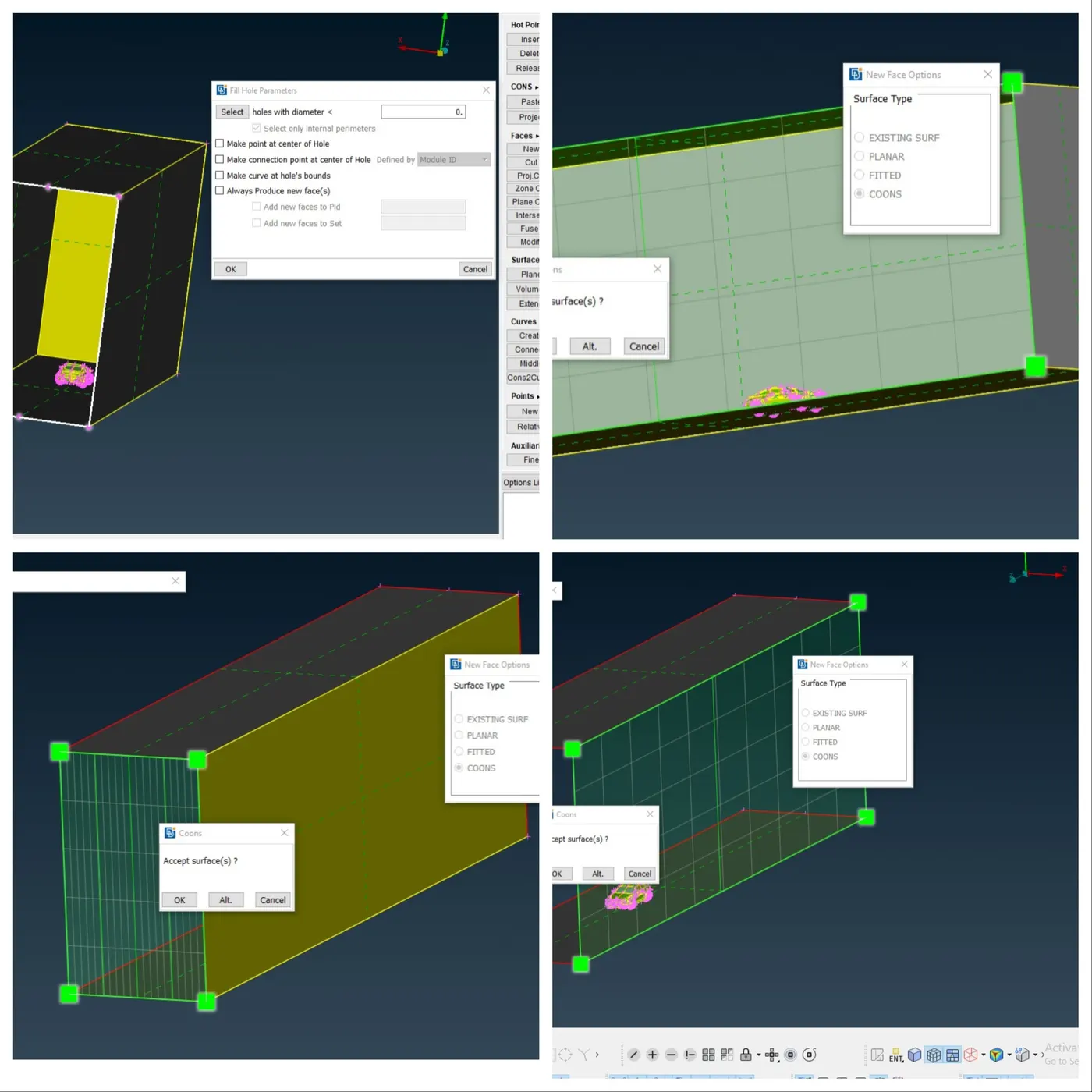
Creation of new surface topo->faces->new is selected then new face options window appears COONS is selected then ,curves is selected by using loop option then scroll button is clicked,COONS window appears then ok button is clicked.
After this hiding whole model,properties window deselecting the visible icon of all PIDs
Curves and points are deleted by following the deleting surface procedure.
30. <!--[endif]-->Topo->faces->offset option is selected then created surface is selected then offset value window appears then 4275 distance is entered and then ok button is clicked.
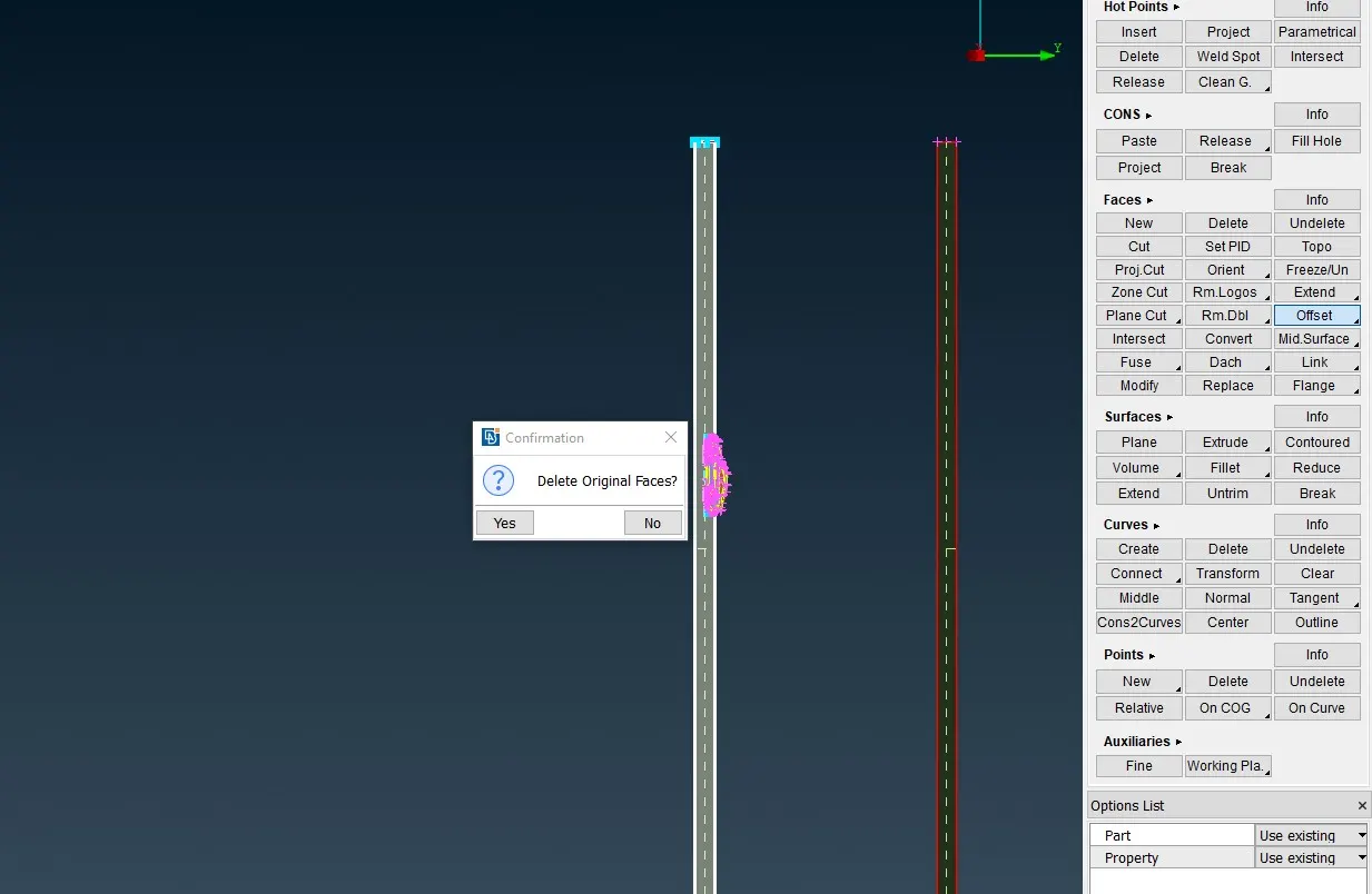
Creation of new surface topo->faces->new is selected then new face options window appears COONS is selected then ,curves is selected by using entities option then scroll button is clicked,COONS window appears then ok button is clicked.this step repeated to create the side and front and rear surface of the wind tunnel.
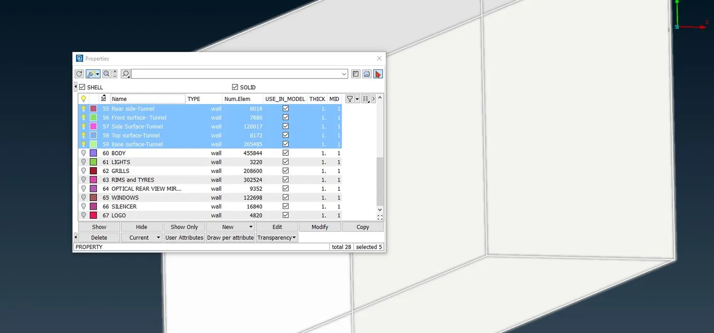
31. <!--[endif]-->Creation of PIDS Lists->properties option is used.Properties window appears then right-click then select new option then select shell property then property window appears entering the name and then click ok button.Then Right-click on the properties window then select apply option then selecting the surfaces by box select then mouse scroll button is clicked.
PIDS are Front,Rear,Side,top,base Surface-Tunnel.
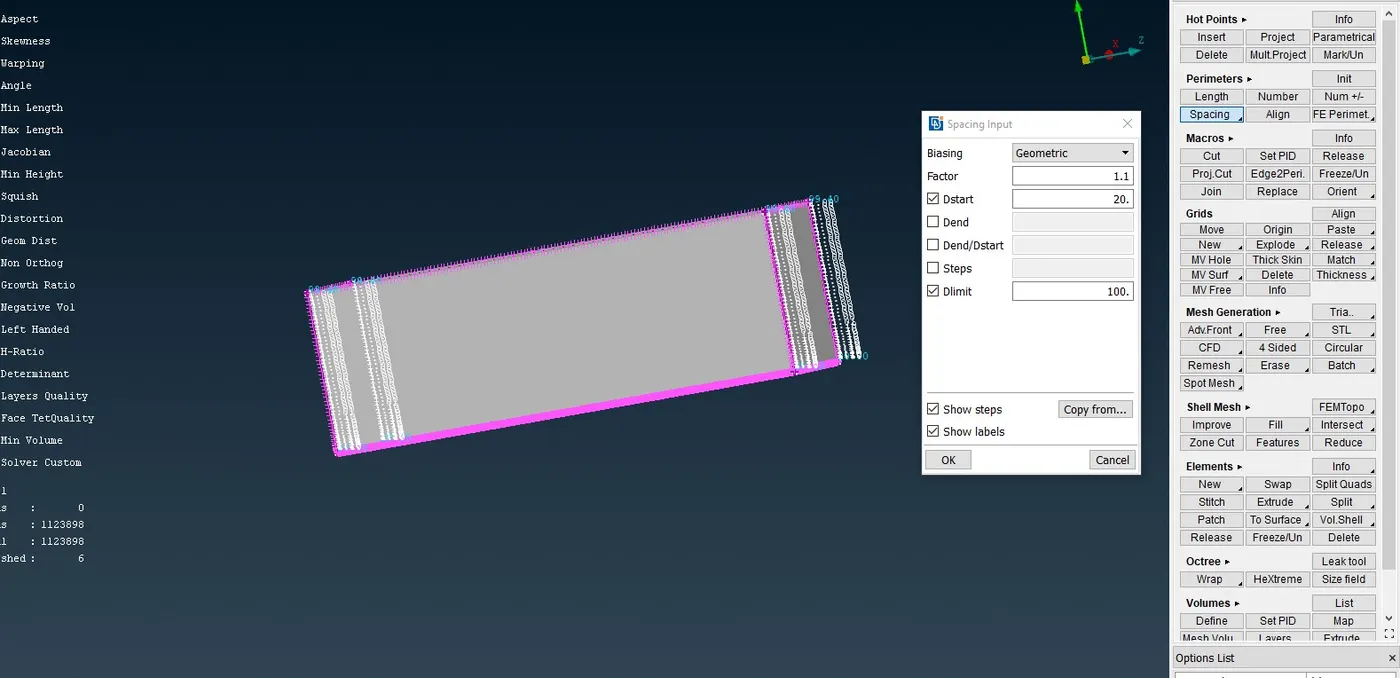
Once again meshing carried out,Mesh->perimeters->length is selected then selection window appears then selected perimeters and the boundary is selected then scroll button is clicked target length is entered then ok button is clicked.
Top surface-100 mm
Base surface-20 mm
Mesh->perimeters->Spacing is selected then spacing input window appears then vertical perimeters are selected with direction ,then biasing is selected as geometric then factor is entered as 1.1 then dstart value is entered as 20 then dlimit as 100 then click ok button
Then isolating by selecting the visible icon on the properties window .utilities->quality criteria then quality criteria presentation parameters window appears then max and min length values are entered then click ok button
|
Maximum length |
Minimum length |
|
|
Top surface |
80 |
120 |
|
Base surface |
15 |
25 |
Then utilities->mesh parameters Is selected then mesh parameters window is open the maximum and minimum length value is entered then click ok button [maximum and minimum length value is described in the table above]
Mesh->meshgeneration->spot mesh-> visible option is selected
Top surface meshing starts from quality criteria then ends at spotmesh visible option then base surface meshing also uses same procedure
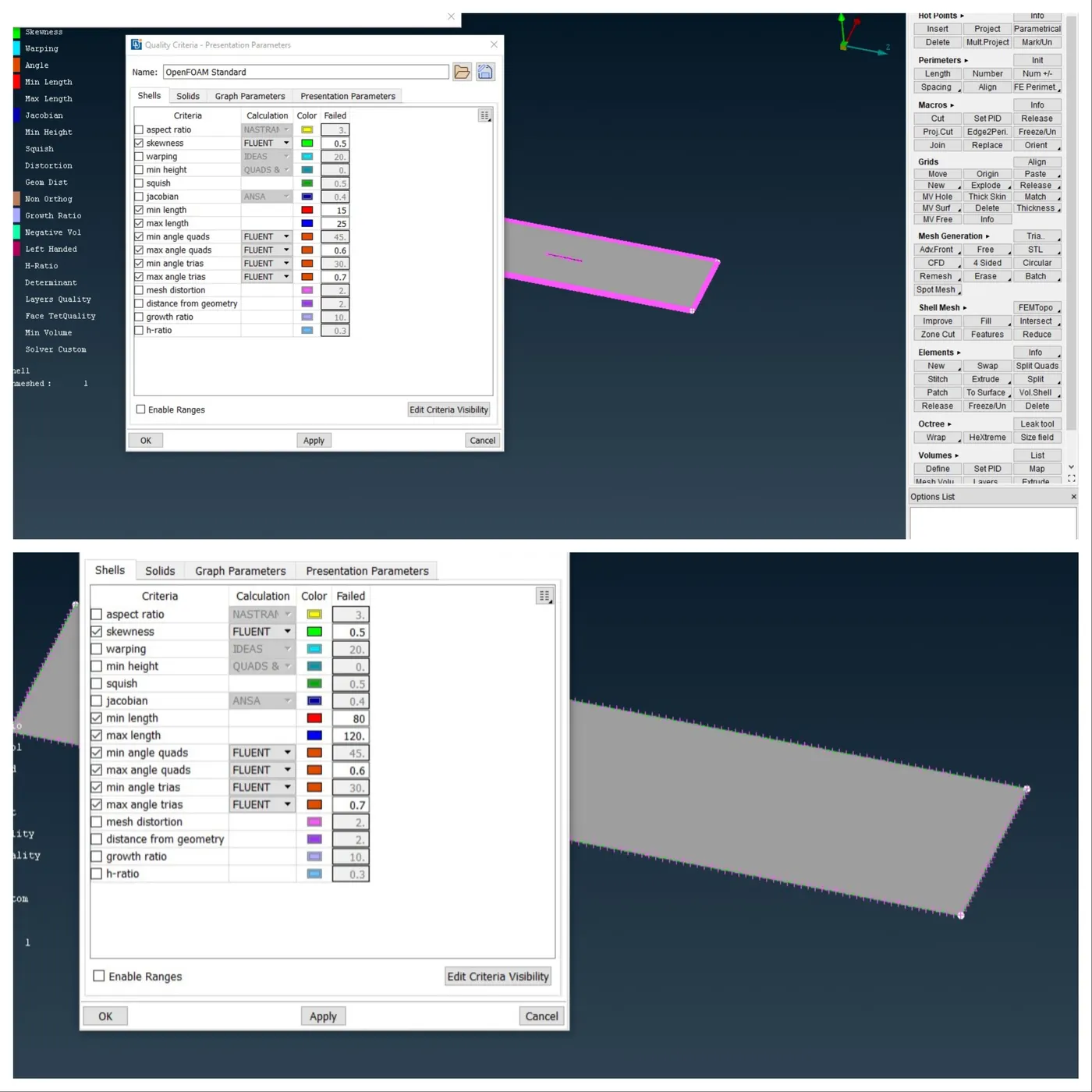
Front ,rear,side surfaces meshing doesnot takes inputs mesh parameters where min and max length is 20 and 100 ,on quality criteria unchecked min and max length.Mesh->meshgeneration->spot mesh-> select option is selected.then entities is selected this will be repeated for three surfaces.
31.Modules->V.mesh->Define option is selected then volumes detection window appears detect on whole db then click ok button then volume window appears [with a few volumes detected on the model] then if we left click the names the volume gets highlighted.in that way what are the volumes presented there is checked.unnecessary volume is deleted by selected the names on the volume window then clicking delete button then right-click on the necessary volume on the volume window then mesh is selected .
Learning Outcomes:
(i)performing Geometry clean up using tools such as cut,new ,Project cut ,intersect under faces ,paste,release,project under CONS,create ,CONS2CURVES under curves, insert,project,parametrical,Delete,release under hotpoints,Delte under utilities
(ii)Made as one volume inside the body PID.
(iii)surface meshing for parts as well as at joints of two different target lengths of surface meshing.
(iv)To create the 3D points by using relative points and creating a surface
(v)Identifying the volumes that needs a mesh
(vi)Meshing the volumes with varying mesh lengths
Result:
from surface meshing,provides the elements upto 1938850
Conclusion:
Cleanup,Surface and volumetric meshing done for the BMW car CAD model.
model is attached in the zip format https://drive.google.com/file/d/13A5ifC0KPtjAI-Ko1UpUyEQHDYzglgs6/view?usp=sharing