Week 4 Challenge : CFD Meshing for BMW car
Aim/Objective
For the given model, check and solve all geometrical errors on half portion and assign appropriate PIDs. Perform meshing with the given Target length and element Quality criteria. After meshing the half model, Do symmetry to the other side.
Target lengths for the different parts of a model are as follow:
- Body - 3 mm
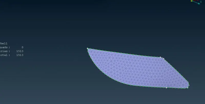
- Lights - 4 mm
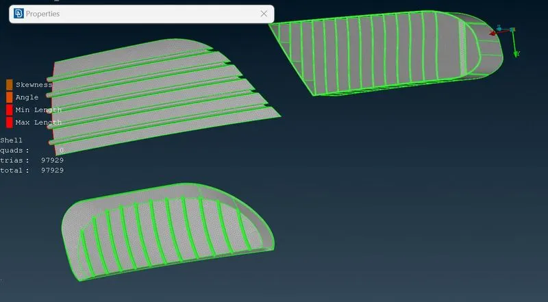
- Grills - 1 mm
- Rims and Tyres - 2 mm
- Optical Rear-view mirror - 2 mm
- Window - 2 mm
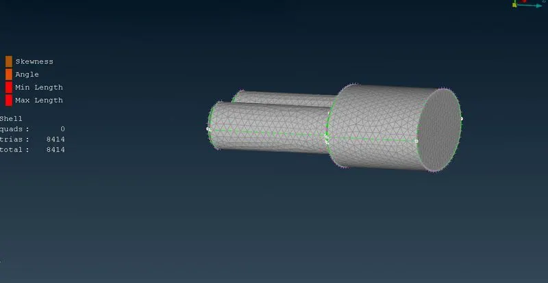
- Silencer - 3 mm
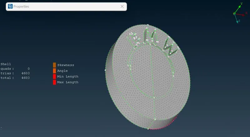
- Logo - 1 mm
Procedure
Geometry Preparation
Import the Geometry Model
File -> open -> (select the file)
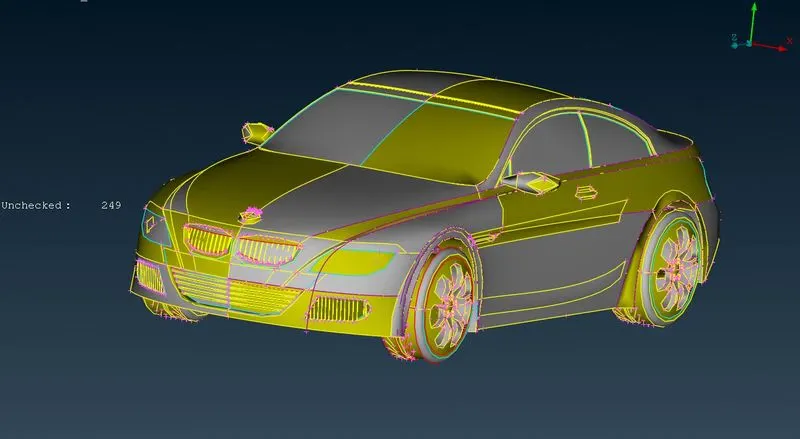
Resolution
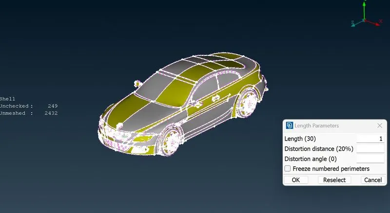
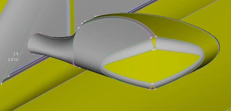
After Importing the model, it needs to be resolved to better capture the model geometry and for our clarity of model.
Initial resolution of geometry:
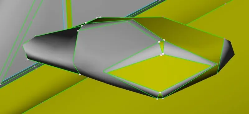
Resolution of Geometry using length parameters:
Final Resolution of geometry:
Geometry check
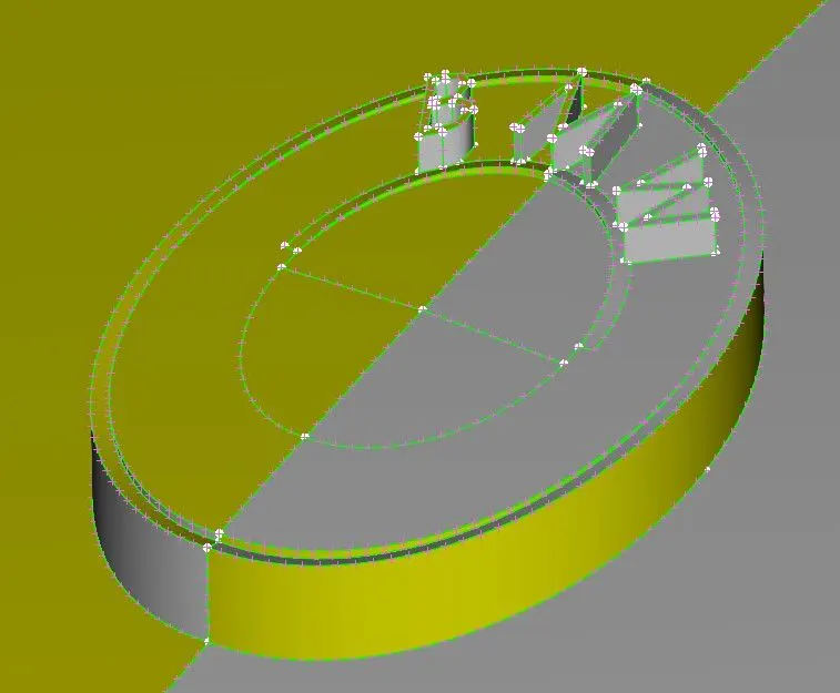
- The Model has a lot of single Cons. “Topo” operation can be performed on the model to join the single cons.
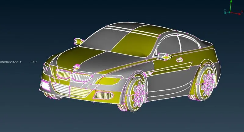
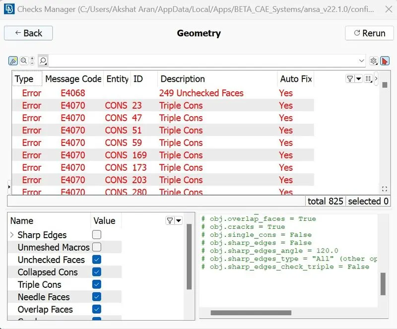
- Geometry check can be performed to detect the geometrical irregularities in the given model: Checks -> geometry check
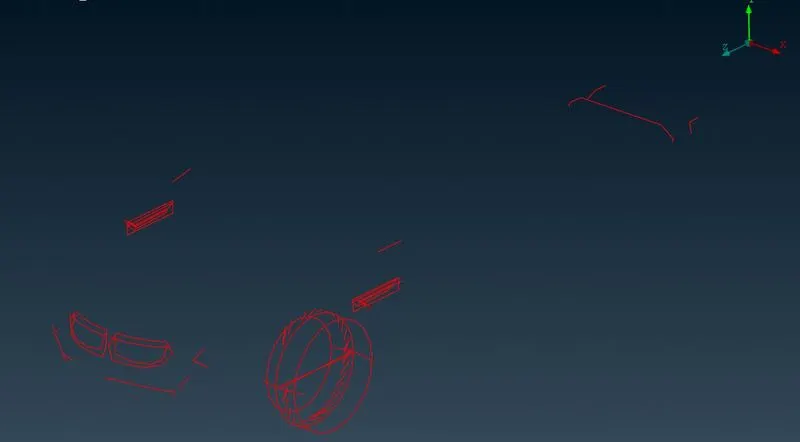
- Wire frame mode -> Selecting only single cons.to be visible -> red lines show the number of missing surfaces.
Topology cleanup
- To ensure efficiency of work, we can delete half of the model and work with the other half. The complete model can be recreated using symmetry option later.
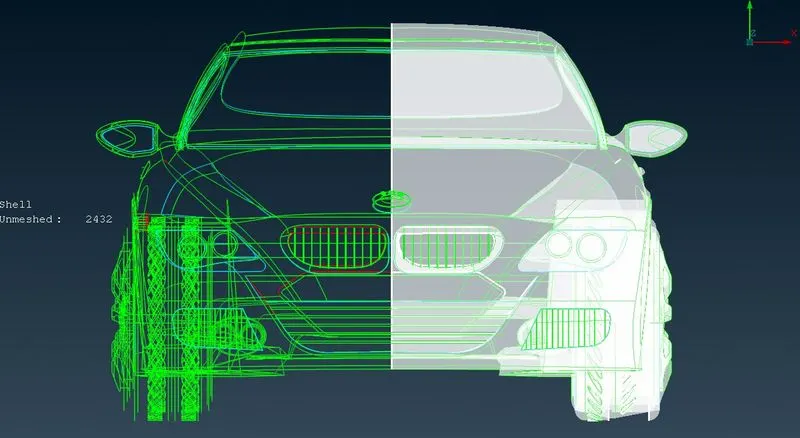
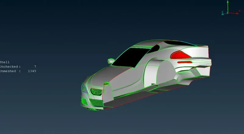
- Unnecessary inside surfaces need to be deleted from the model since we will need only the outer surface to generate the volume mesh.
- Next step involves solving the topology issues of all parts individually using the available tools in the TOPO deck of ANSA.
- The Topology needs to be solved for the following surfaces:
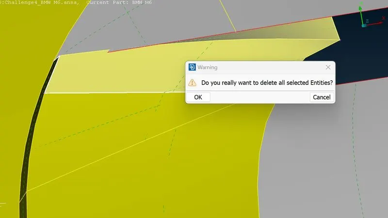
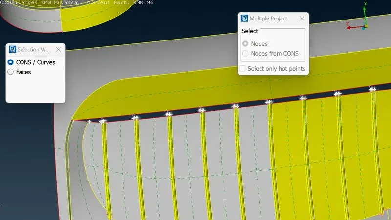
Topo Cleanup: Grills
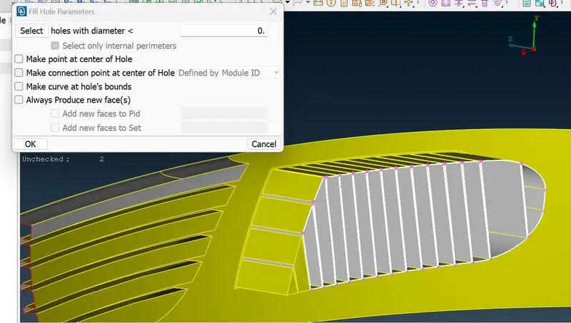
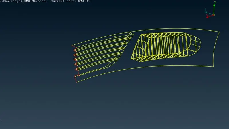
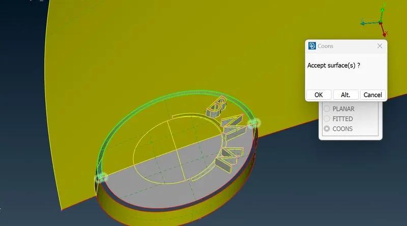
Topo Cleanup: Logo
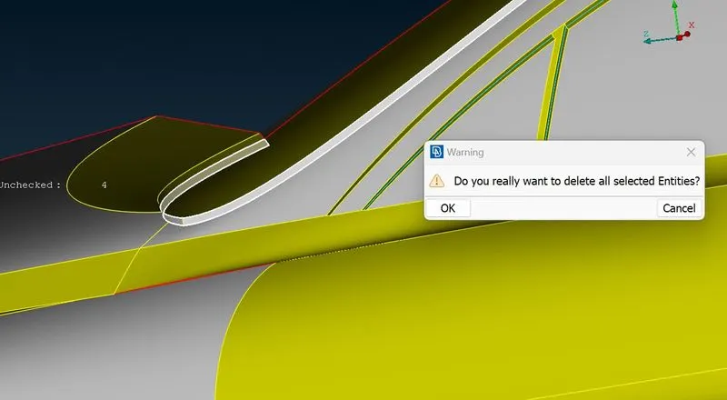
Topo Cleanup: Windshield
Topo Cleanup: Side Windows
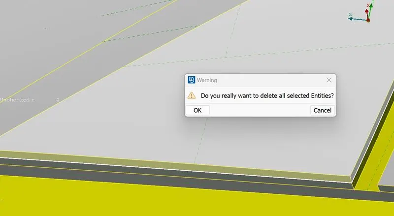
Topo Cleanup: Rear Windshield
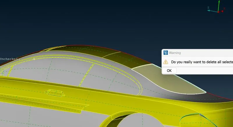
Topo Cleanup: Rear Lights
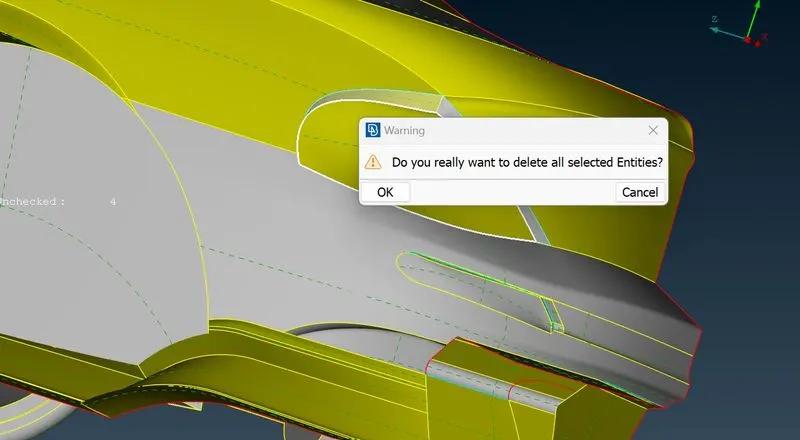
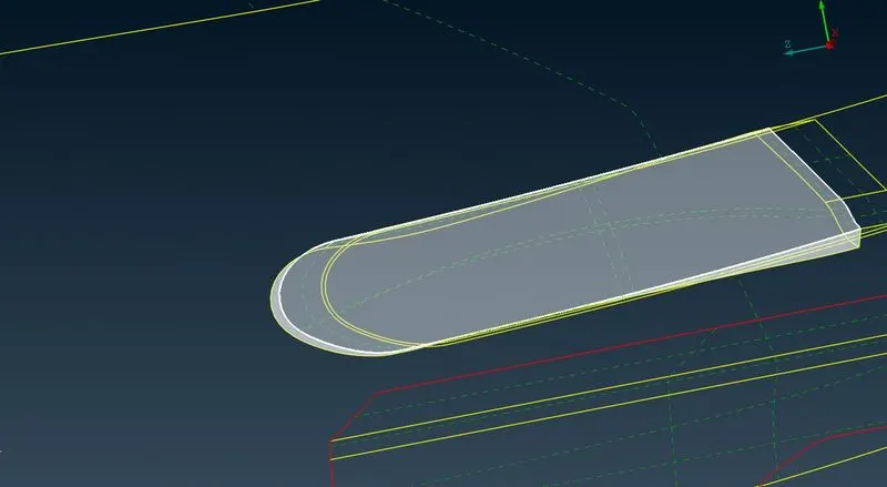
Topo Cleanup: Side Feature
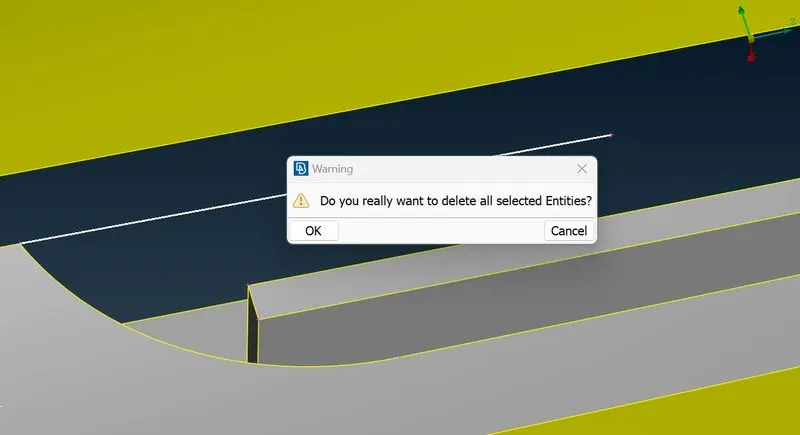
Topo Cleanup: Side Mirror
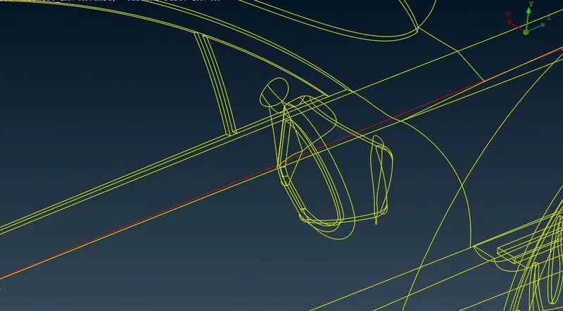
Topo Cleanup: Tyres and Rims
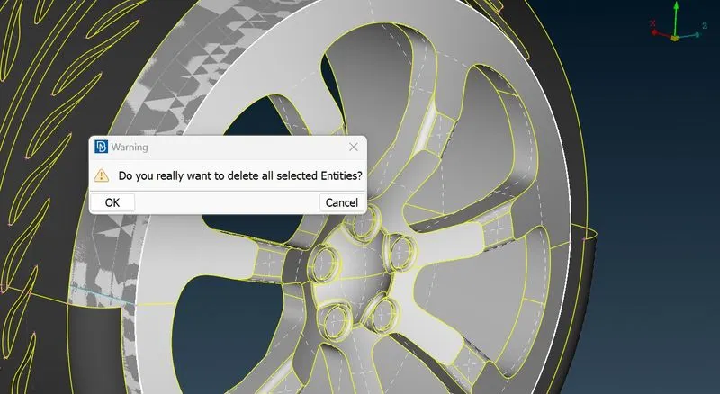
Topo Cleanup: Bottom Surface
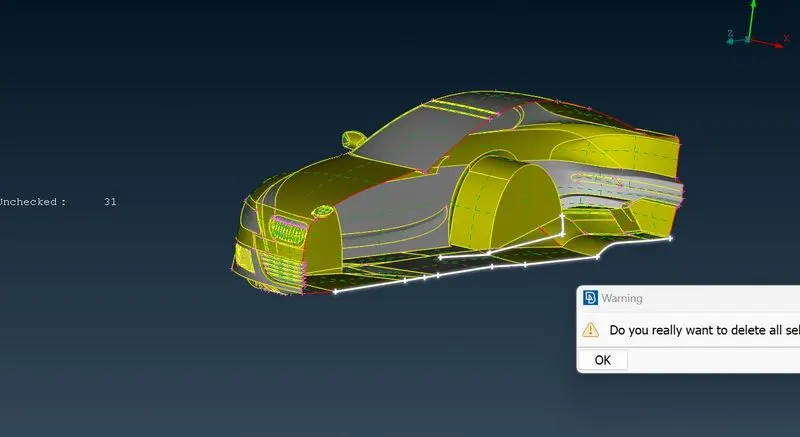
- After performing the topo cleanup for the whole model there are only single CONS left in the model. This is due to the absence of half geometry.
- It is confirmed through geometry check that the single cons are at places where we deleted half geometry.
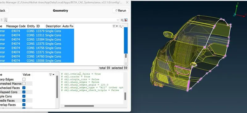
Creating and Assigning PID’s
- For convenient handling and meshing of the model PIDs need to be created and assigned to the respective components.
- PID Creation: Properties -> Right click -> PSHELL -> PSHELL -> (specify PID details like Name, etc.)
- Assigning PIDs: Properties -> select the PID to be assigned -> Right click -> Apply -> select the corresponding Macros -> Middle click (to assign the PID)
After completing the above-Mentioned Procedure, the components assigned to various PIDs need to be checked again.
PID: Logo
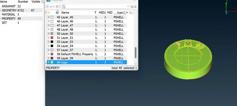
PID: Lights
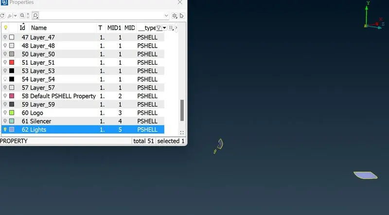
PID: Grills
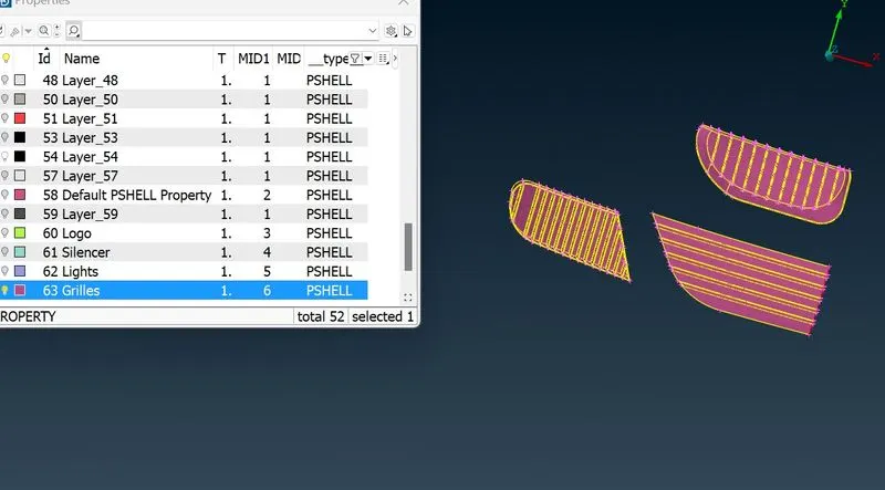
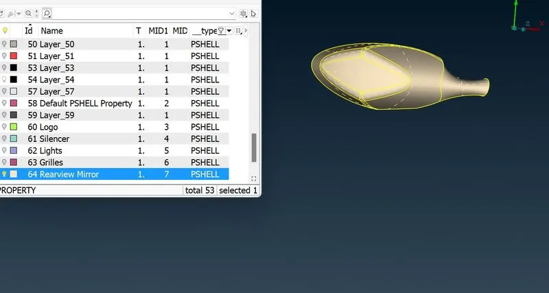
PID: Rear View Mirrors
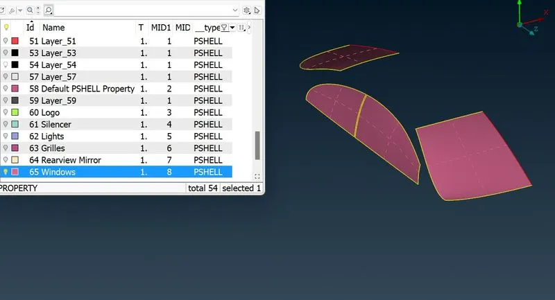
PID: Windows
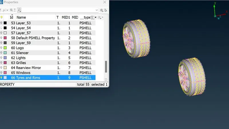
PID: Tyres and Rims
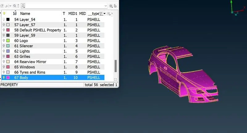
PID: Body
Meshing
Surface Meshing
Mesh Quality Criteria
- Every component needs different quality criteria based on the required target length
- To set Quality Criteria: Quality Criteria -> Set Min and Max Length
Mesh Parameters
- Every component needs different mesh parameters based on the required target length
- To set Mesh Parameters: Mesh Parameters -> Specify the Target Length, Specify the min length, Element type = Tria
Mesh Length
- Different target lengths need to be set up for each component as per the problem statement
- To Set Target length on Perimeters: Perimeters -> Length -> perimeters -> select the CONS on which mesh length needs to be specified -> Specify the required Target length -> Middle click (apply mesh length setting)
- To Set Target length on Macros: Perimeters -> Length -> macros -> select the Faces on which mesh length needs to be specified -> Specify the required Target length -> Middle click (apply mesh length setting)
Mesh Generation
- Mesh needs to be generated for each component according to the problem statement
- To generate surface meshes: Spot Mesh -> Select all parts to be meshed -> Middle Click
- Mesh Generation needs to be performed along with the above specified operations in specific order for each component separately
- Order to be followed for mesh generation: Specify Quality criteria -> Specify Mesh Parameters -> Assign Mesh Length -> Generate Surface Mesh
The generated surface meshes are as follows:
Mesh for Logo
Mesh for Silencer
Mesh for Lights:
Mesh for Grills:
Mesh for Rear-view Mirrors:
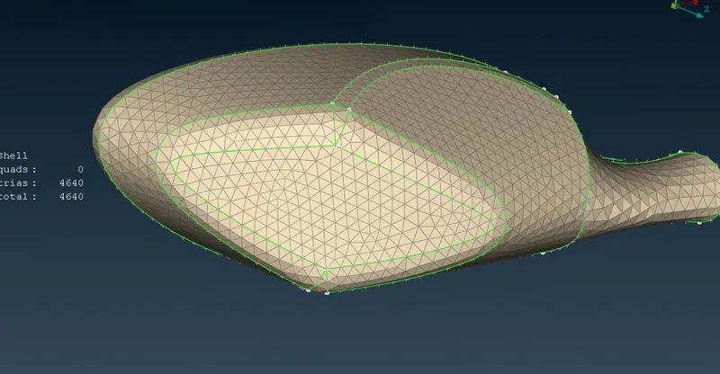
Mesh for Windows:
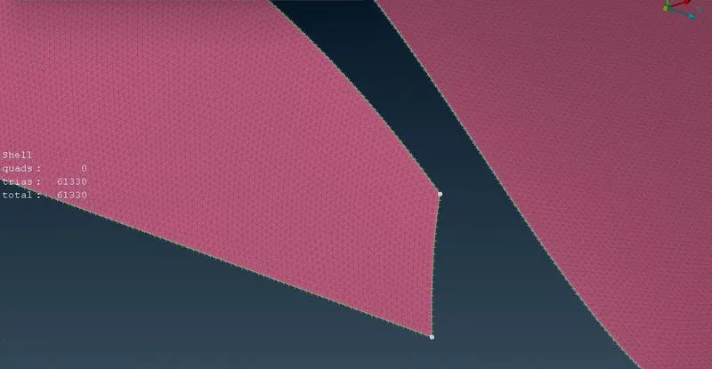
Mesh for Tyres and Rims:
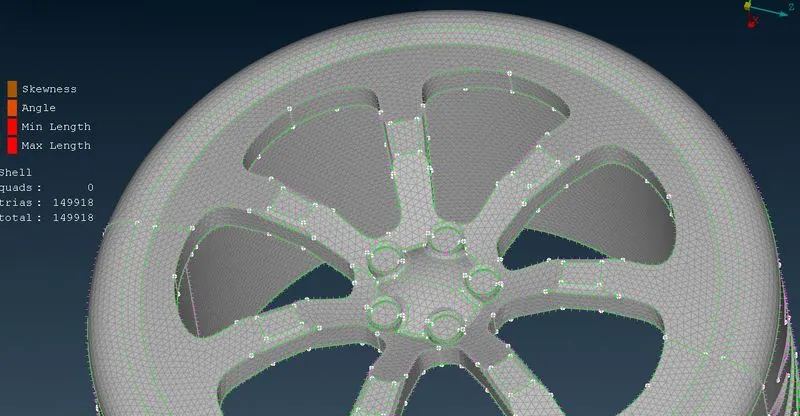
Mesh for Body:
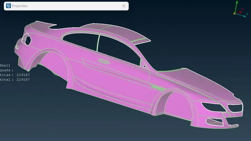
Symmetry
- Since half of the model was deleted during the start, the current model needs to be mirrored about the middle plane to obtain the complete vehicle.
- To copy the entities about a middle plane:
Transform -> Copy -> Entities -> {Perform box Selection} -> {Middle Click} -> Symmetry -> Mirror 3 points plane -> {Select three points that lie on the middle plane}
- We need to check and solve the geometry again to ensure there are no abnormalities in the final model.
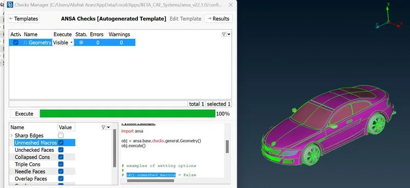
Wind Tunnel Creation
Since the applicatrion of this model involves external flow analysis, We need to create a wind tunnel around the car
- The dimensions of the wind tunnel need to be according to certain thumb rules as mentioned below-
- Considering the length of vehicle as “X” = 1300 (through measure tool)
- Base surface can be at approximately at 75mm distance from bottom of vehicle.
- Front surface of the wind tunnel should be “4X” distance from the front of the vehicle.
- Back surface of the wind tunnel should be “6X” distance from the back of the vehicle.
- Height of wind tunnel should be “3X” distance from the top of the vehicle
- Side surfaces of the wind tunnel should be “X” distance from each side of the vehicle.
- Based on above criteria, points need to be created below the vehicle to define the perimeter of the Base Surface.
- To create a point from an existing point: Points -> Relative -> {Specify the X/Y/Z distance and middle click}
- Select a point in middle of car from bottom surface and create a point 75 mm below it.
- With reference to that point create a point in front of car and a point at the back of the car based on above mentioned criteria.
- With reference to the front, middle and back points create points on either sides based on the above mentioned Criteria.
- From the created points, make a perimeter using “Curves” tool.
- Make a surface from the created Perimeter.
- The Bottom surface can be offset by some distance (according to above mentioned criteria for wind tunnel) to obtain the Top Surface of the Wind Tunnel.
- Using the Base and Top Surfaces, all surface of Wind tunnel can be generated.
- After creating the wind tunnel, points and curves which were created earlier need to be deleted.
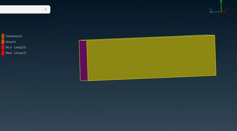
- After creation of Surfaces, PIDS need to be created and assigned to appropriate Wind tunnel Surfaces.
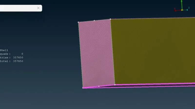
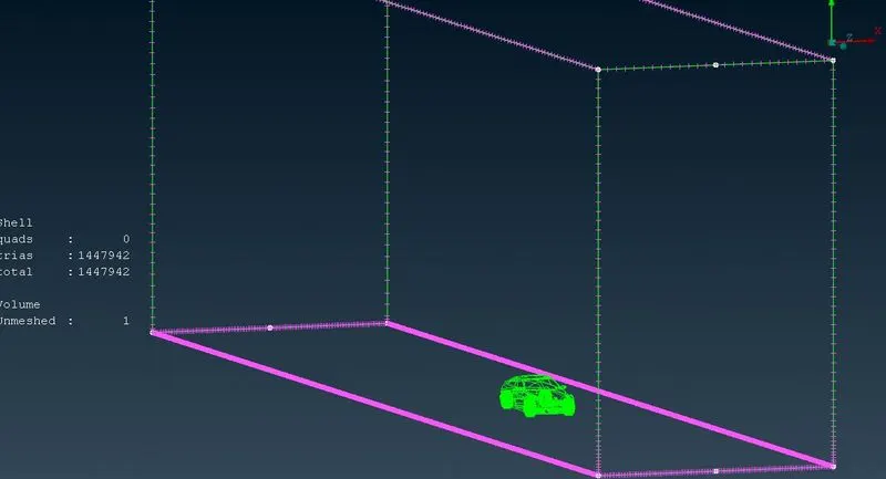
- After Applying the PIDs, Surface mesh needs to be generated for the Wind Tunnel surfaces. (Top - 100 mm target length, Base- 20 mm target length, Sides – gradually increasing mesh parameters using “spacing” tool)
Volume Meshing
- Define the Volumes: Volume Mesh -> Volumes -> Define -> select “whole db” -> select “ok”
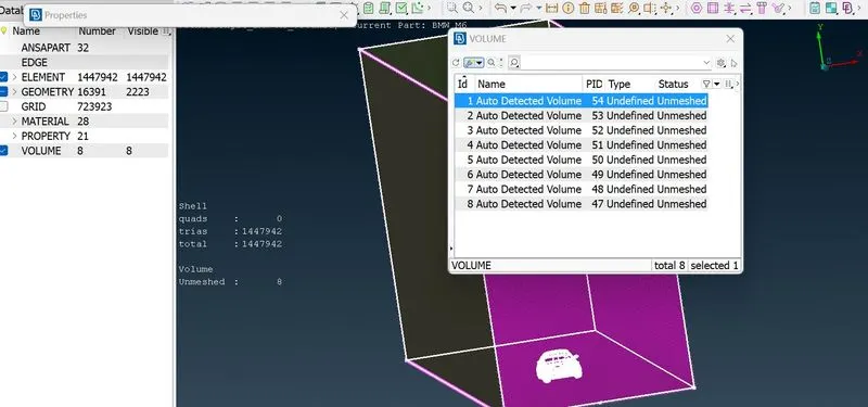
- From the volumes detected by the software, select the volumes that are not needed.
- Delete the selected volumes. Now only the required volumes are left.
- Generate volume mesh (Tria CFD) for the required volumes.
- To generate volume mesh: Right click on the volume to be meshed -> remesh
NOTE: In this project the volume mesh is not generated in the submitted model due to the time constraints and hardware limitations
Learning Outcomes
- Topology Cleanup
- Surface Meshing
- Using Symmetry to minimise work and maximise efficiency
- Volume Meshing
Result
- Geometry checked for abnormalities and all geometrical errors solved
- Surface Mesh Generated for the Half Model
- Full Vehicle Model created from the half model.
- Wind Tunnel created and meshed based on thumb rules for dimensions.
- Volume mesh is not generated in the submitted model due to the time constraints and hardware limitations. Total Elements in Surface Mesh = 1447942
Conclusion
- In case of Models with symmetry, Half/Quarter Models can be used to save manual work, and computation time.
- Learned advanced application of TOPO deck for geometry cleanup.
- Learned surface meshing in case of different components with varying mesh lengths.
- Learned how to create wind tunnel and what thumb rules are used for the same.