Project 1 : CFD Meshing for Tesla Cyber Truck
Aim/Objective
For the given model, check and solve all geometrical errors and Assign appropriate PIDs. Perform meshing with the suitable Target length and element Quality criteria.
Procedure
Step 1: Geometry Preparation
Import the Geometry Model
File -> open -> (select the file)
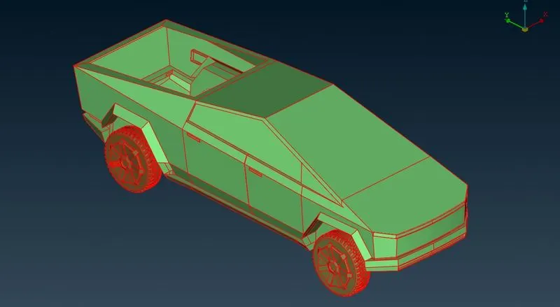
Step 2: Topology clean-up
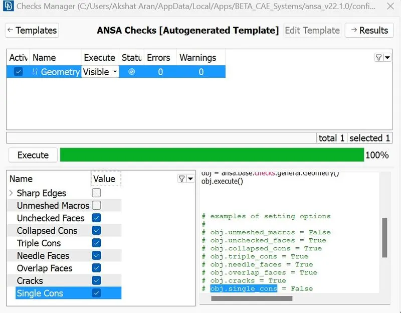
- The Model has a lot of single Cons. “Topo” operation can be performed on the model to join the single cons.
- Wire frame mode -> selecting only single cons.to be visible -> red lines show the number of missing surfaces.
- Unnecessary inside surfaces also need to be deleted from the model since we will need only the outer surface to generate the volume mesh.
- Next step involves solving the topology issues of all parts individually using the available tools in the TOPO deck of ANSA.
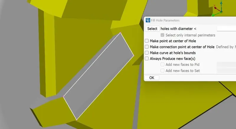
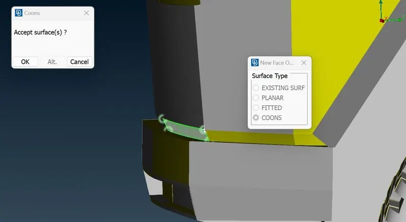
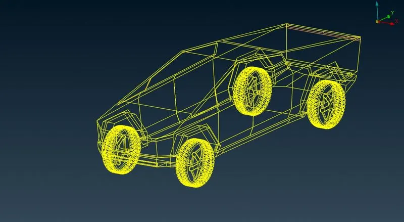
Step 3: Wind Tunnel Creation
Since the application of this model involves external flow analysis, we need to create a wind tunnel around the car
- The dimensions of the wind tunnel need to be according to certain thumb rules as mentioned below-
- Considering the length of vehicle as “X” = 5715 m (through measure tool)
- Base surface can be at approximately at 475mm distance from bottom of vehicle.
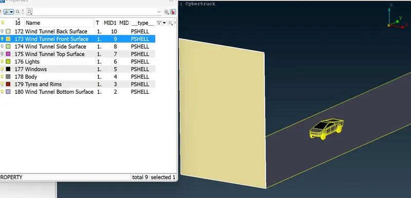
- Front surface of the wind tunnel should be “4X” distance from the front of the vehicle.
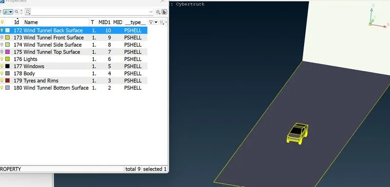
- Back surface of the wind tunnel should be “6X” distance from the back of the vehicle.
- Height of wind tunnel should be “3X” distance from the top of the vehicle
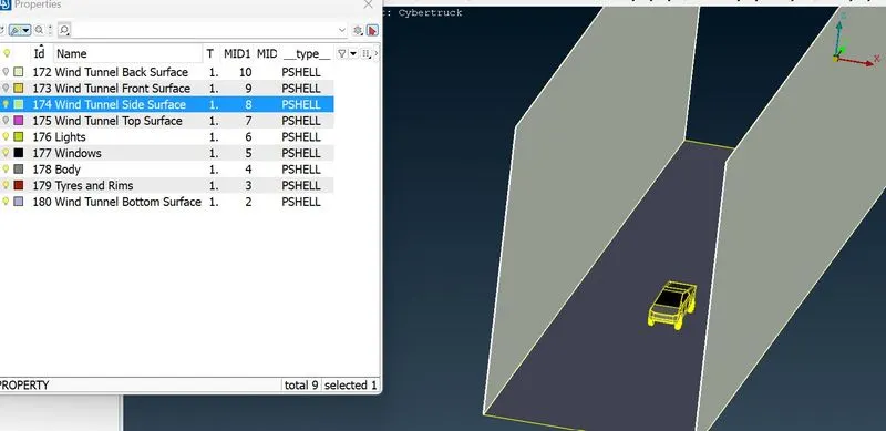
- Side surfaces of the wind tunnel should be “X” distance from each side of the vehicle.
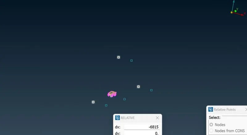
- Based on above criteria, points need to be created below the vehicle to define the perimeter of the Base Surface.
- To create a point from an existing point: Points -> Relative -> {Specify the X/Y/Z distance and middle click}
- Select a point in middle of car from bottom surface and create a point below it.
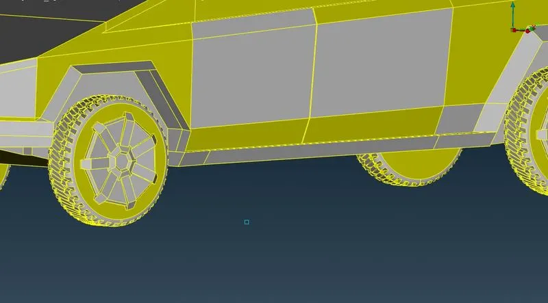
- With reference to that point create a point in front of car and a point at the back of the car based on above mentioned criteria.
- With reference to the front, middle and back points create points on either sides based on the above mentioned Criteria.
- From the created points, make a perimeter using “Curves” tool.
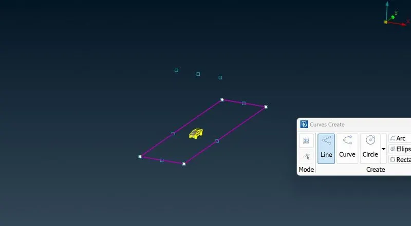
- Make a surface from the created Perimeter.
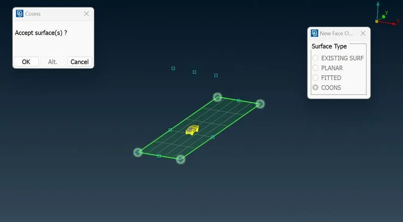
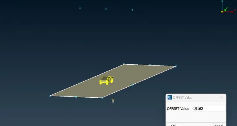
- The Bottom surface can be offset by some distance (according to above mentioned criteria for wind tunnel) to obtain the Top Surface of the Wind Tunnel.
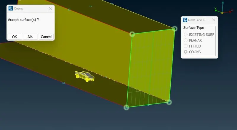
- Using the Base and Top Surfaces, all surface of Wind tunnel can be generated.
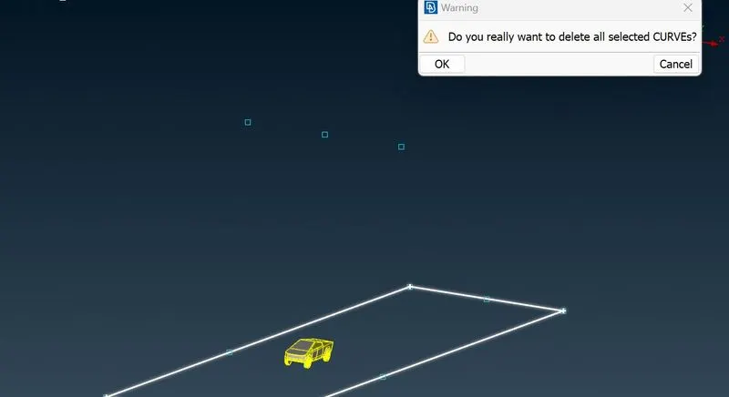
- After creating the wind tunnel, points and curves which were created earlier can be deleted.
Step 4: Creating and Assigning PID’s
- For convenient handling and meshing of the model PIDs need to be created and assigned to the respective components.
- PID Creation: Properties -> Right click -> PSHELL -> PSHELL -> (specify PID details like Name, etc.)
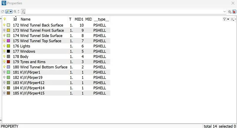
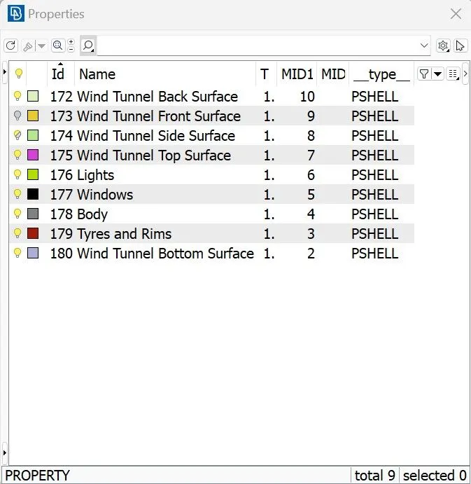
- Assigning PIDs: Properties -> select the PID to be assigned -> Right click -> Apply -> select the corresponding Macros -> Middle click (to assign the PID)
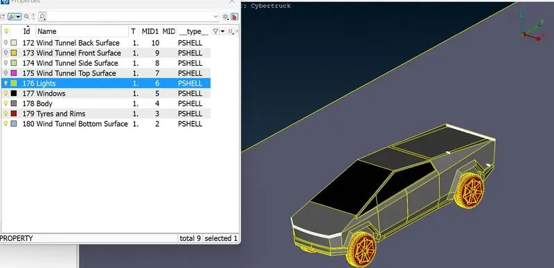
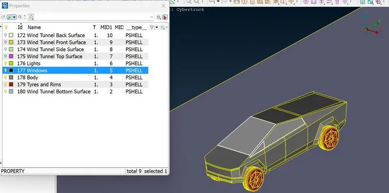
- After completing the above-Mentioned Procedure, the components assigned to various PIDs need to be checked again.
PID: Lights
PID: Windows
PID: Tyres and Rims
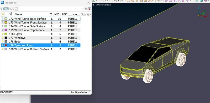
PID: Body
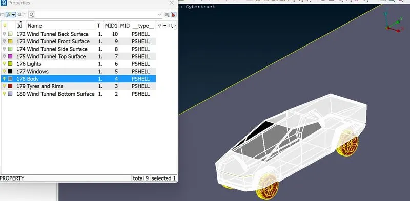
PID: Wind Tunnel Bottom Surface
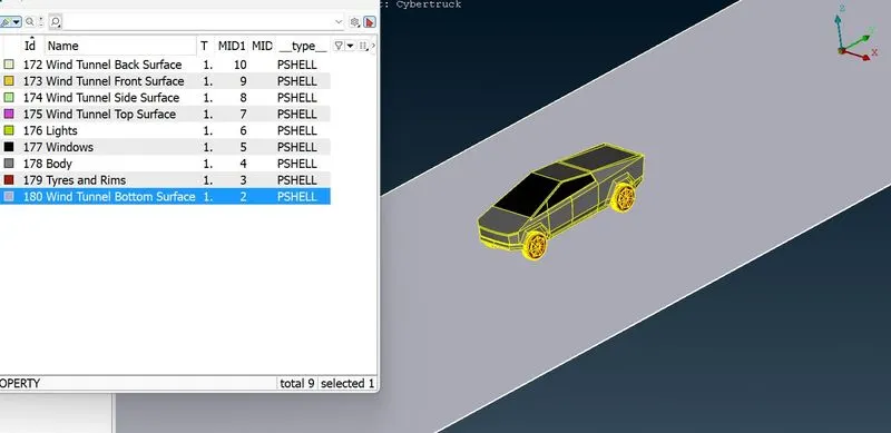
PID: Wind Tunnel Top Surface
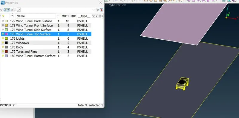
PID: Wind Tunnel Front Surface
PID: Wind Tunnel Back Surface
PID: Wind Tunnel Side Surface
Step 5: Meshing
5.1: Surface Meshing
5.1.1: Mesh Quality Criteria
- Every component needs different quality criteria based on the required target length
- To set Quality Criteria: Quality Criteria -> Set Min and Max Length
5.1.2: Mesh Parameters
- Every component needs different mesh parameters based on the required target length
- To set Mesh Parameters: Mesh Parameters -> Specify the Target Length, Specify the min length, Element type = Tria
5.1.3: Mesh Length
- Different target lengths need to be set up for each component as per the problem statement
- To Set Target length on Perimeters: Perimeters -> Length -> perimeters -> select the CONS on which mesh length needs to be specified -> Specify the required Target length -> Middle click (apply mesh length setting)
- To Set Target length on Macros: Perimeters -> Length -> macros -> select the Faces on which mesh length needs to be specified -> Specify the required Target length -> Middle click (apply mesh length setting)
- Target Length for Vehicle Body = 10 mm
- Target Length for Windows = 15 mm
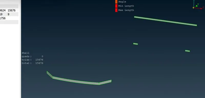
- Target Length for Lights = 5 mm
- Target Length for Tyres and Rims = 15 mm
- Target Length for Wind Tunnel Surfaces: Top Surface - 200 mm target length, Base Surface- 40 mm target length, Side Surfaces – gradually increasing mesh parameters using “spacing” tool
5.1.4: Mesh Generation
- Mesh needs to be generated for each component according to the problem statement.
- Surface mesh needs to be generated for the Wind Tunnel surfaces also.
- To generate surface meshes: Spot Mesh -> Select all parts to be meshed -> Middle Click
- Mesh Generation needs to be performed along with the above specified operations in specific order for each component separately
- Order to be followed for mesh generation: Specify Quality criteria -> Specify Mesh Parameters -> Assign Mesh Length -> Generate Surface Mesh
The generated surface meshes are as follows:
Mesh for Lights:
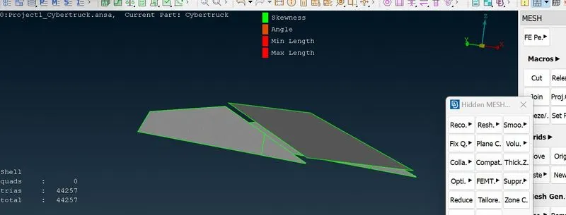
Mesh for Windows:
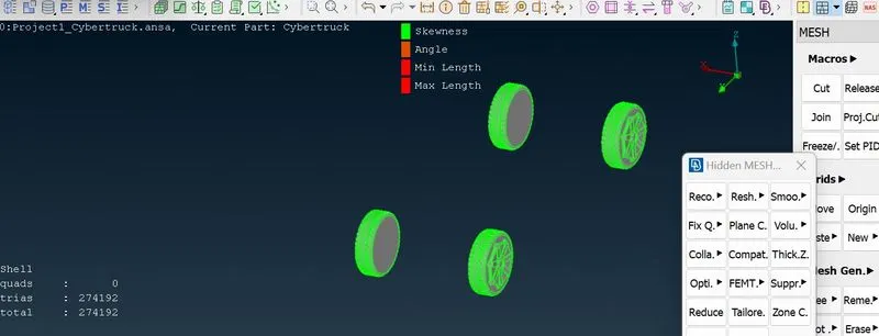
Mesh for Tyres and Rims:
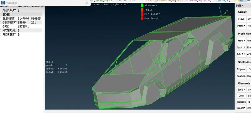
Mesh for Body:
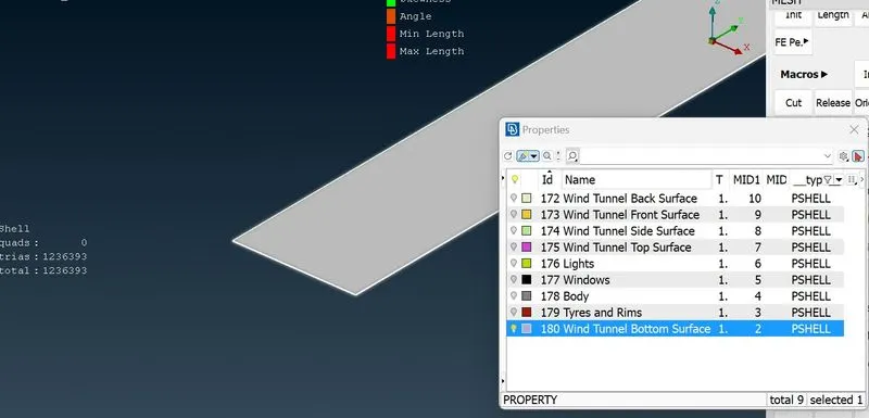
Mesh for Wind Tunnel Bottom Surface:
Mesh for Wind Tunnel Top Surface:
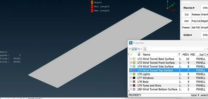
Mesh for Wind Tunnel Front, Back and Side Surfaces:
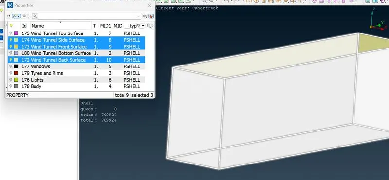
5.2: Volume Meshing
- Define the Volumes: Volume Mesh -> Volumes -> Define -> select “whole db” -> select “ok”
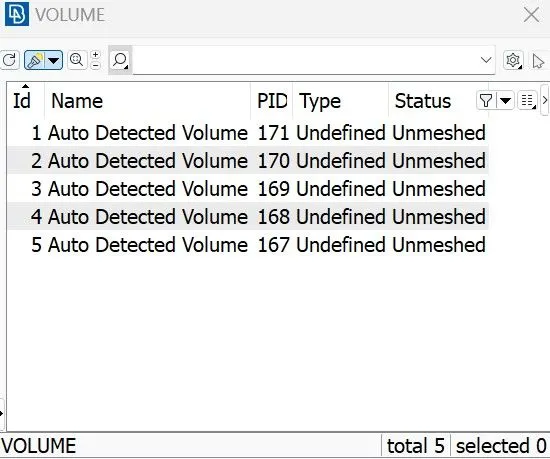
- From the volumes detected by the software, select the volumes that are not needed.
- Delete the selected volumes. Now only the required volumes are left.
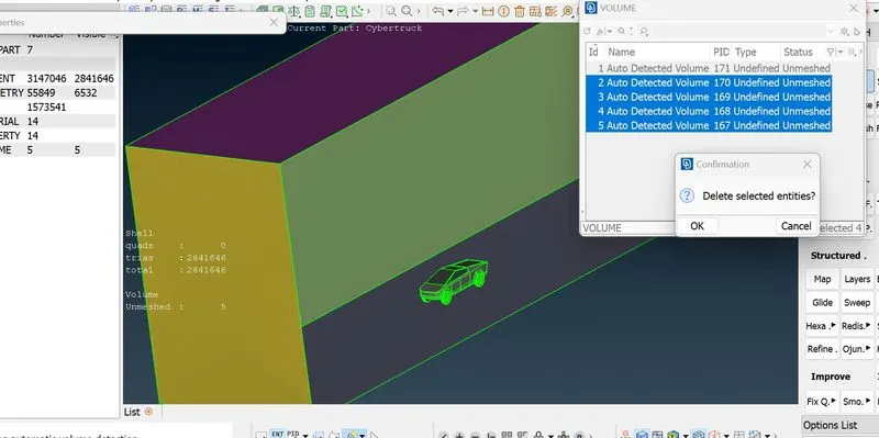
- Generate volume mesh (Tria CFD) for the required volumes.
- To generate volume mesh: Right click on the volume to be meshed -> remesh
NOTE: In this project the volume mesh is not generated in the submitted model due to the time constraints and hardware limitations
Learning Outcomes
- Topology Clean-up
- Surface Meshing
- Wind Tunnel Creation
Result
- Geometry checked for abnormalities and all geometrical errors solved
- Surface Mesh Generated for the given Model
- Wind Tunnel created and meshed based on thumb rules for dimensions.
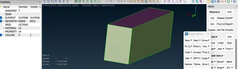
- Volume mesh is not generated in the submitted model due to the time constraints and hardware limitations. Total Elements in Surface Mesh = 147048
Final Surface Mesh:
Conclusion
- In case of Models with symmetry, Half/Quarter Models can be used to save manual work, and computation time for complicated models. This is not used in this project since the topology clean-up was feasible for full model directly.
- Learned advanced application of TOPO deck for geometry clean-up.
- Learned surface meshing in case of different components with varying mesh lengths.
- Learned how to create wind tunnel and what thumb rules are used for the same.