Week 4 Challenge : CFD Meshing for BMW car
AIM
- To Clear all the geometrical errors of the given model.
- Do surface meshing of the model with the respective quality criteria and taget length.
- To ensure there is zero off elements in the surface meshing.
- Create a wind tunnel for CFD analysis of the model.
Procedure
- Import the geometry file into ANSA software by File>Open>file location.
- The initail view of the geometry shows lot of single cons.
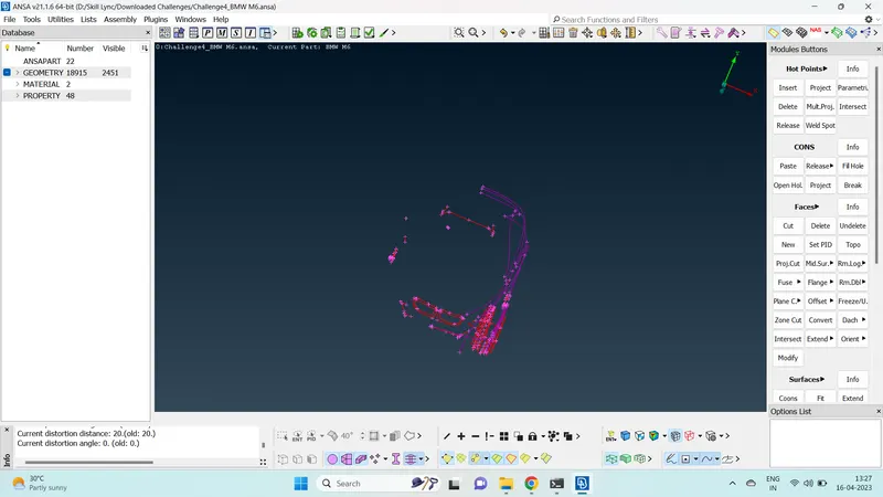
- The TOPO fucntion was performed on the whole body to join any missed surfaces and cons.
- Closer observation of the model shows that the surafaces are very coarse and needs increase in resolution.
- One way to fix this is using the Fine function in auxilary tool box.
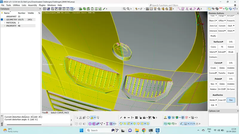
- But this is a very time consuming process. So to increase the resolution of the whole body in a quick manner. Go to mesh module and update the length function as 1 mm in perimeter and macros. This resolves the geometry resolution very quickly.
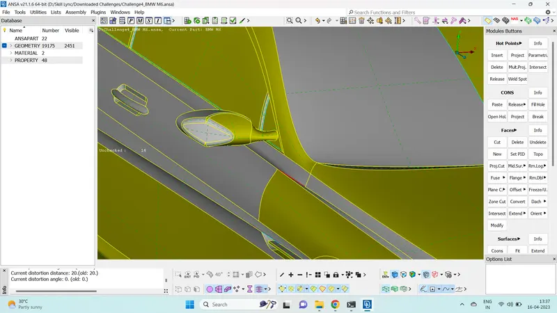
- Once the geometry is in proper resoltuion, we have to solve all the single Cons and triple cons present in the geometry.
- Also we need to make a common volume inside the car and eradicate any material voulme of the car so that we can. delete the volume in a single go in volumteric meshing. Since we are concerned about the CFD analysis of the outside of the car, the inside volume has no significance.
- Also upon examination, we find that that the car is symmetric. We can delete half of the car except logo part for easy geometrical clean up and time saving.
- Use not option to hide the parts that you want to keep and Use delete function to delete the unwanted half of the car.
- After carefully hiding the required regions, delete the half using delete function.
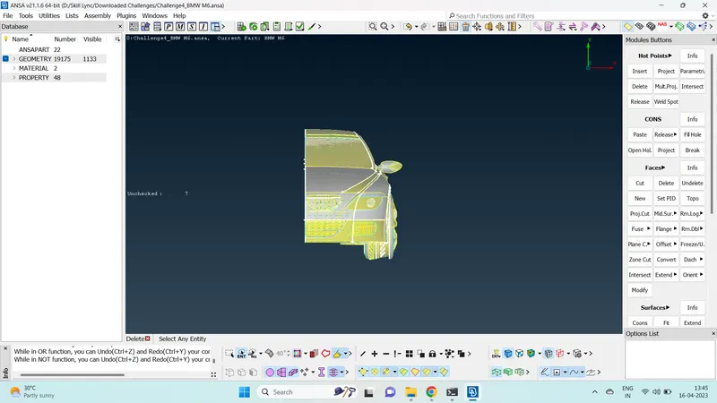
- We can move onto solving the single cons and triple cons.
- For ease of operation, it is better to isolate the part you want to work on using !not option and use the lock function.
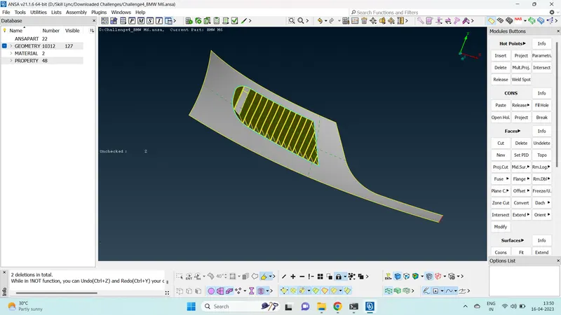
- Since we are only concerened on the outside of the car, surfaces from the inside can be deleted to form a common volume inside the car. It should be performed in such a way that the geometrical view from the outside is not affected.
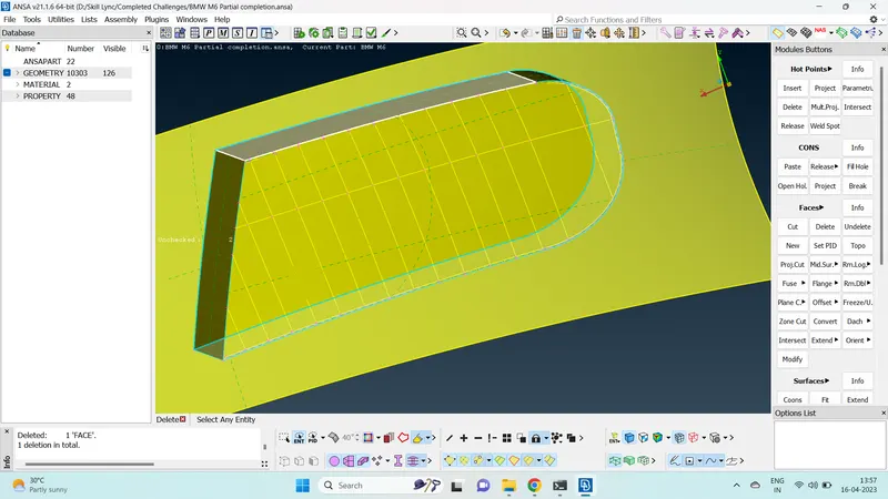
- Once the unwanted surfaces are deleted, it is observed that the ribs form a material volume. The surfaces needs to be created in such a way that the back side of the ribs are open and the spaces between the ribs are closed to form a common volume for the car.
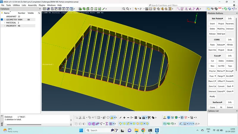
- Make appropriate cuts in the required positions to rectify complicated surfaces by deleting existing surface and creating new surface.
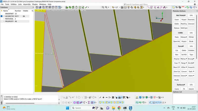
- The unwanted extended surfaces can be deleted by making appropriate cuts and using delete function.
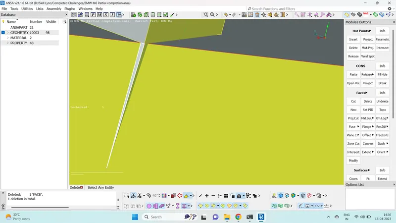
- The curved surfaces create distortion when we create new surfaces with them.
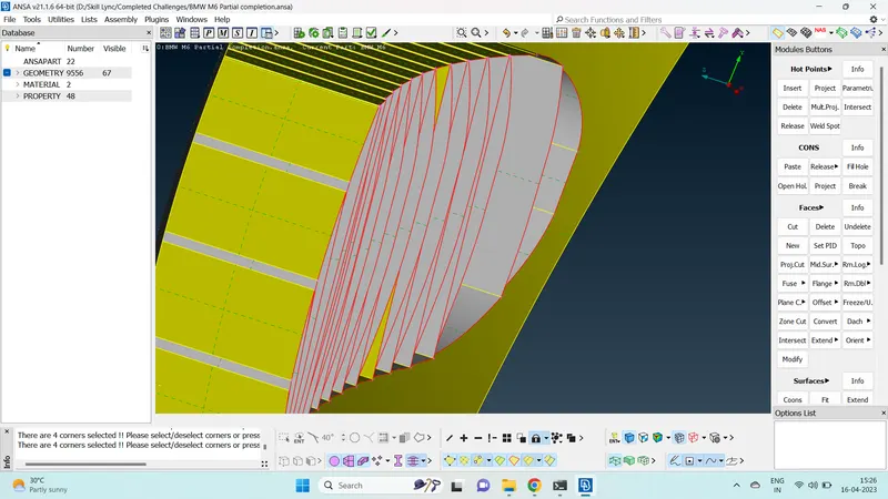
- We use cut option to create a straight line from above and delete the curved surfaces.
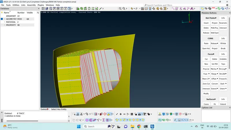
- Once this has been done, we can move onto creating surfaces between the ribs using faces>new option.
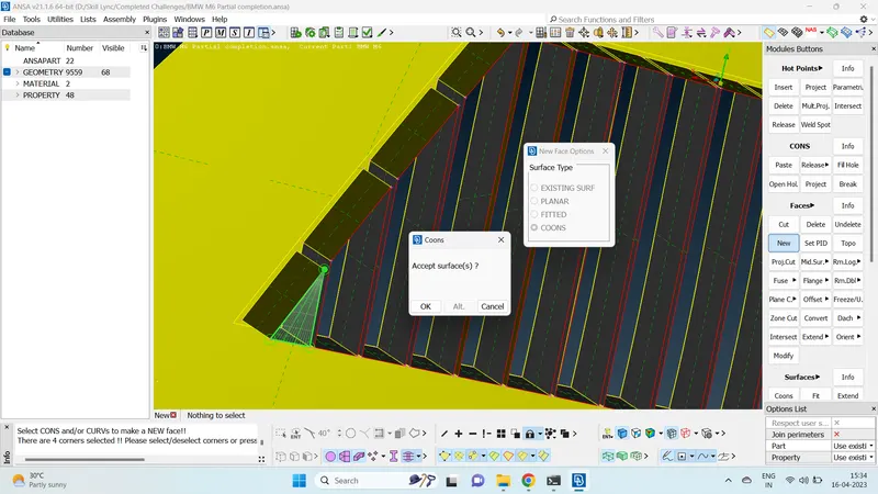
- Once the lower grill is completed we can move onto other parts of the geometry.
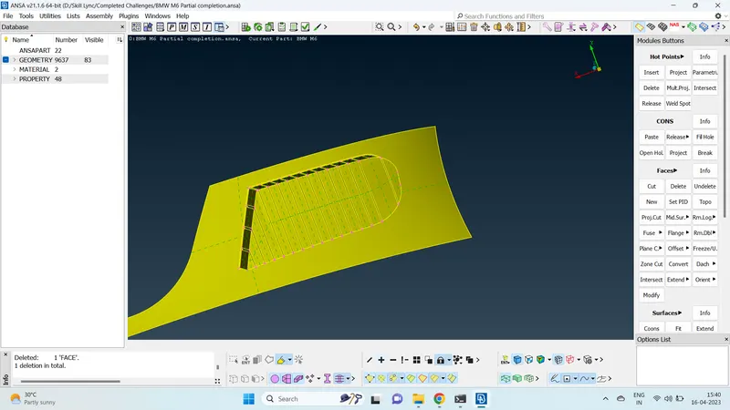
- Release the lock function and call back all the geometry.
- Isolate another part you want to work on using !not function and lock the part.
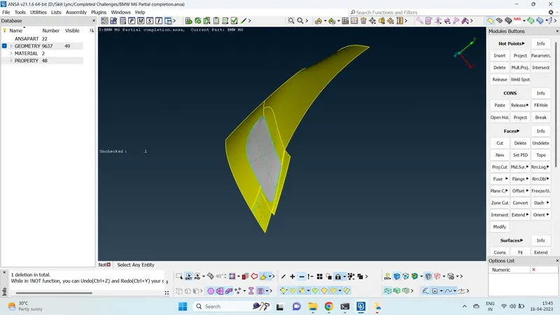
- Since we are not concerned about the inside volume, delete unwanted surface from inside and make a common volume of the car.
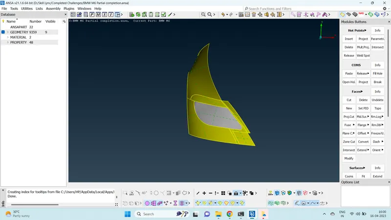
- Once the head lamp area is corrected, we can move onto other parts of the car by releasing the lock.
- Isolate another part of the car where you want to do geometry clean up and apply lock.
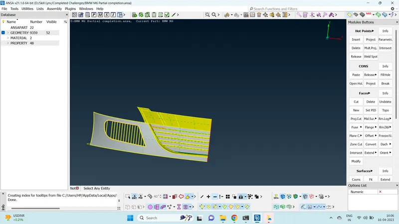
- Delete unwanted surfaces from inside and create a common volume inside the car.
- Project option can be used to project cons onto surfaces.
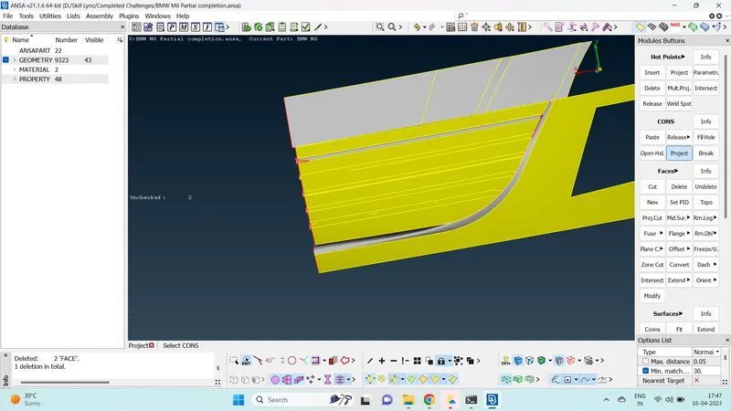
- Delete unwanted surfaces, create cuts and new surfaces appropriately.
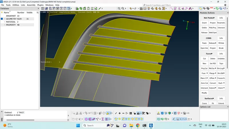
- Perform checks on isolated parts to confirm that there are no other errors except the intended single cons for symmetry.
- Once the part is done, isolate another part of the car where you want to perform geometrical cleanup.
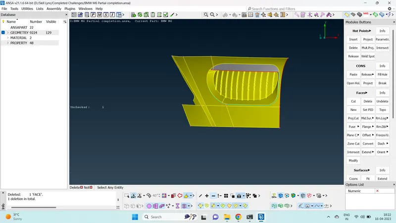
- Delete unwanted surfaces from inside to create a common volume for the car.
- Sharp corners have to be avoidede while geometry clean up as they can cause problems while doing volumetric meshing.
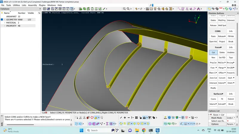
- The grill is cleaned up in such a way that it forms a common volume for the car.
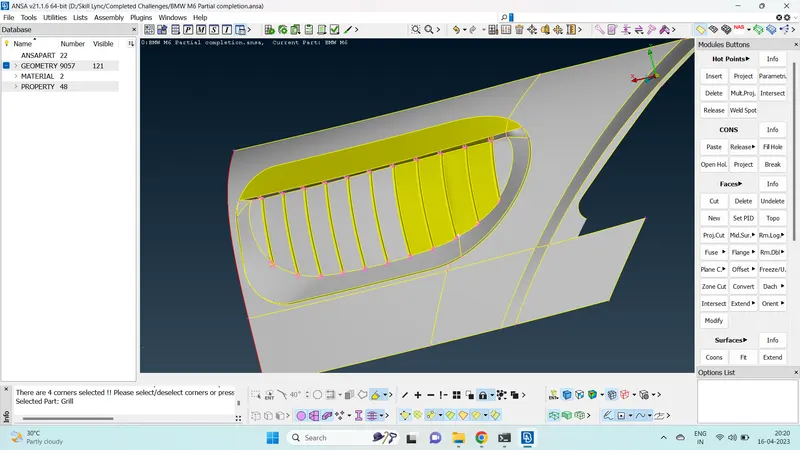
- Similary, isolate another part of the car where you want to do geometric clean up.
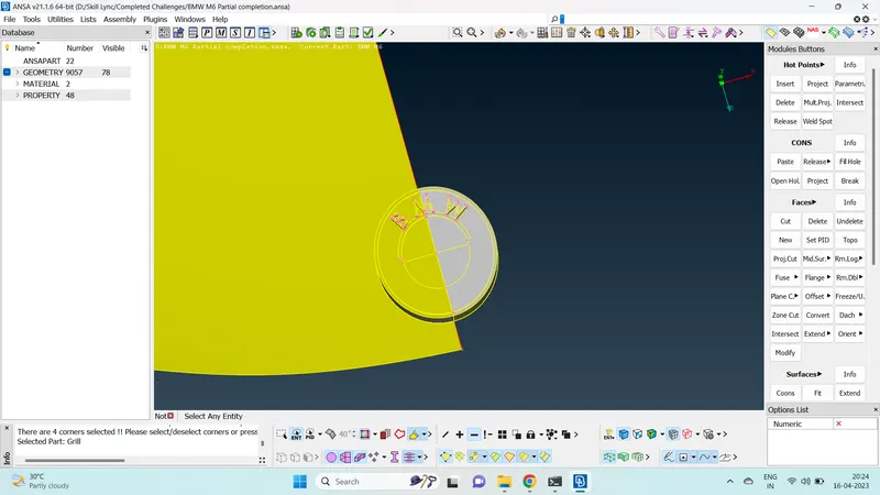
- Surfaces from the inside are deleted to create a common volume.
- It is seen that the logo is forming single con at the bottom side.
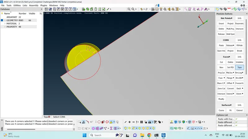
- We can use extend option here to extend the single con of the logo onto the hood.
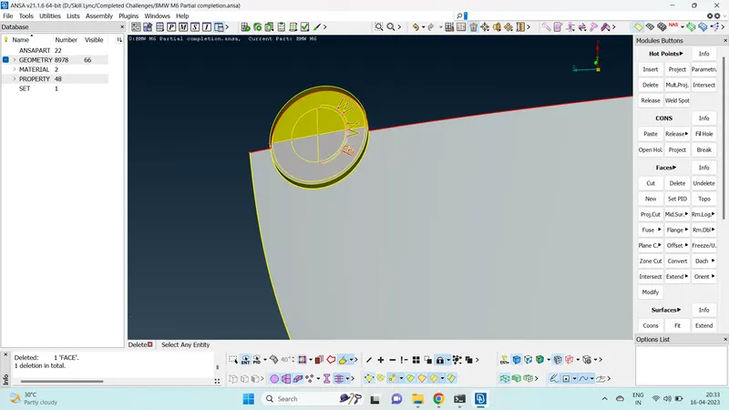
- Delete very small surfaces of the logo and create a common new surface there so that they won't fail quality criteria in the future.
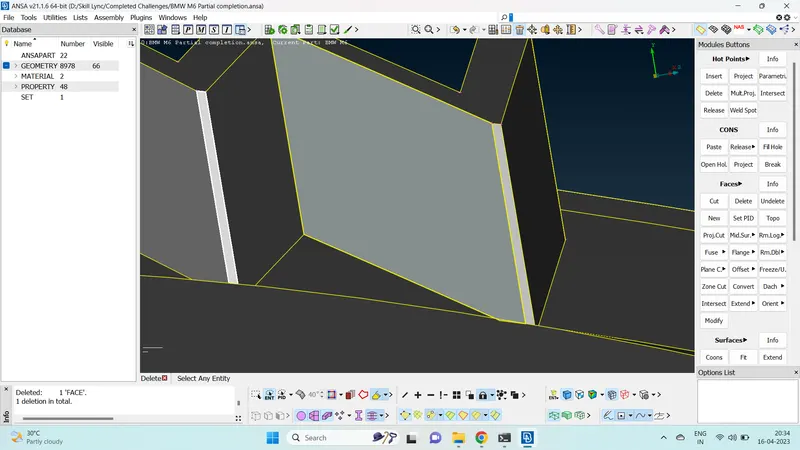
- Once the logo is cleaned up.
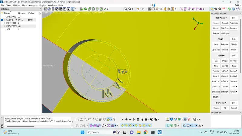
- We can move to another part of the geometry.
- We can easily resolve the triple cons of the windows and indicator by removing the surfaces inside the car.
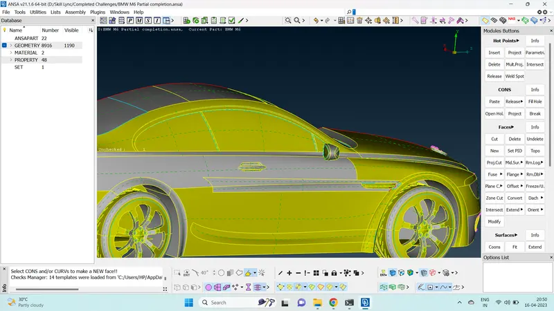
- The extend option can be used at the inidicator part to extend the single cons onto the surfaces.
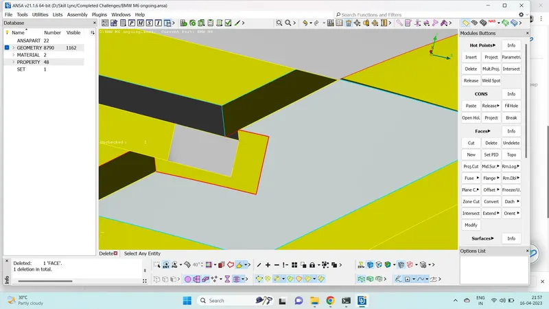
- Various cuts and new surfaces are created to make a common volume for the inidicator part.
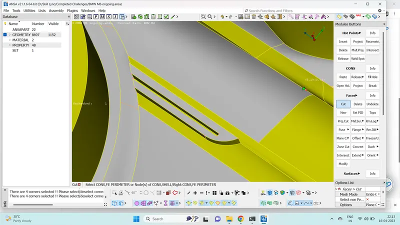
- The windows, tail light and indicator are cleaned up such that they form a common volume inside the car.
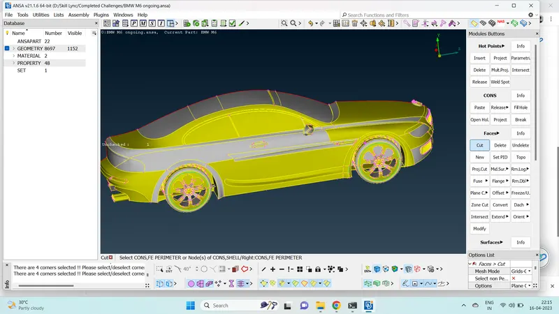
- Next the rear view mirror is isolated using !not function.
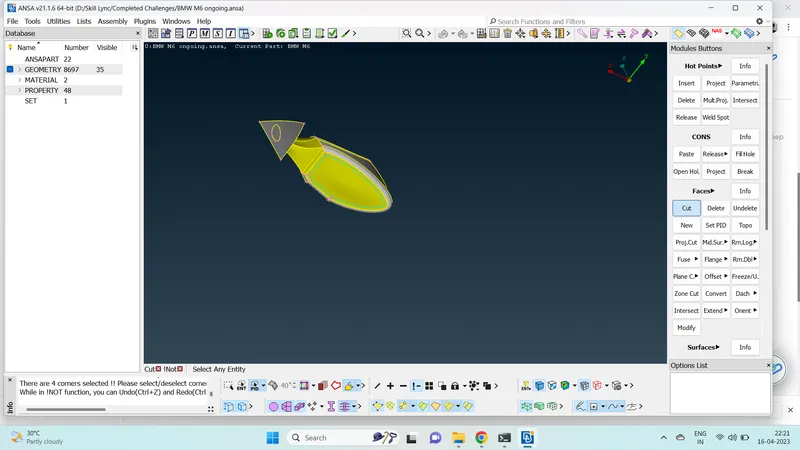
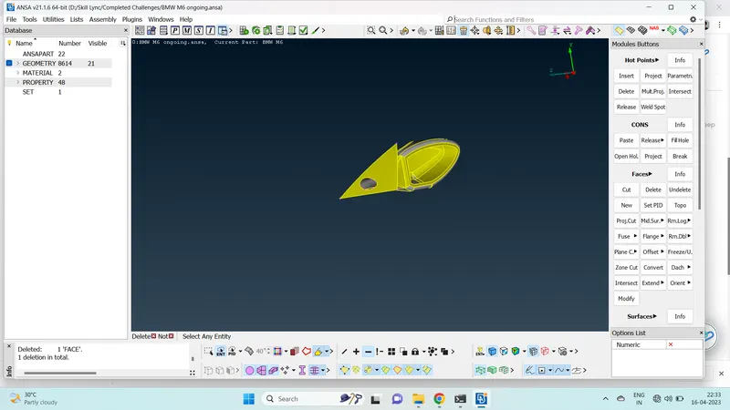
- The material volume of the mirror is deleted by deleting various surfaces inside the rear view mirror.
- An opening is also provided at the quarter glass of the car so that the rear view mirror forms a common volume with the car.
- Next part we have is the silencer of the car. Isolate the part using !not function and lock the part.
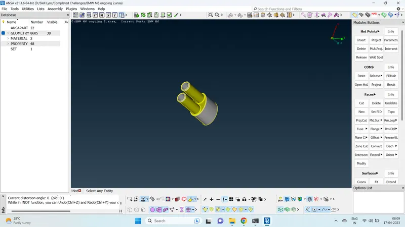
- Since the silencer is seperate from the car, the silencer part will have a separate volume.
- Ensure that the silencer has no single and triple cons by doing geometrical checks.
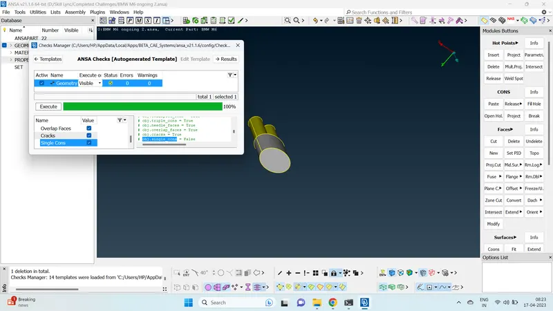
- We can isolate the tyres next using !not function.
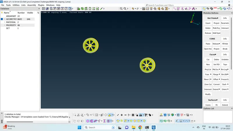
- The tyre is also seperate from the car. The tyres will also have their seperate volumes.
- The triple cons of the tyres are rectified by deleting the inside surface.
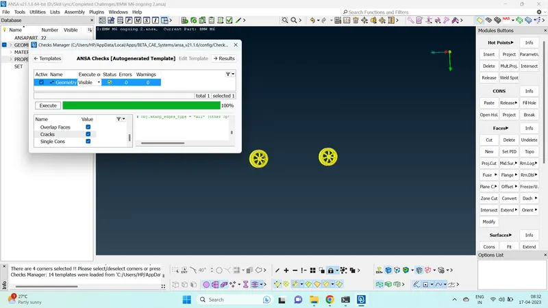
- It is seen that the tyres are intersecting with the body. This needs to be resolved.
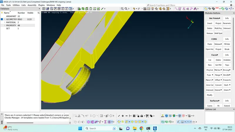
- It is seen that the wheel arch is penetrating the car floor but not forming any cons at the point of penetration.
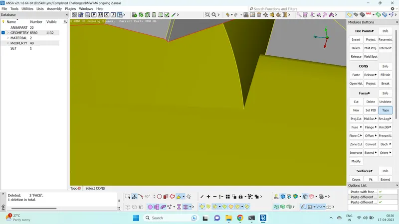
- We can use intersect function here to form cons at the point of intersection.
- Curves>create function can be used to trace out the section of the floor geometry.
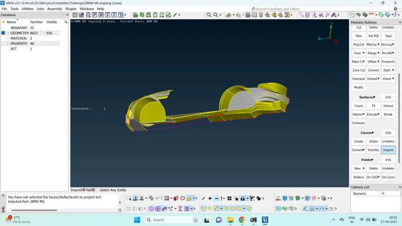
- Once the floor is rectified, make sure to delete all the created cons.
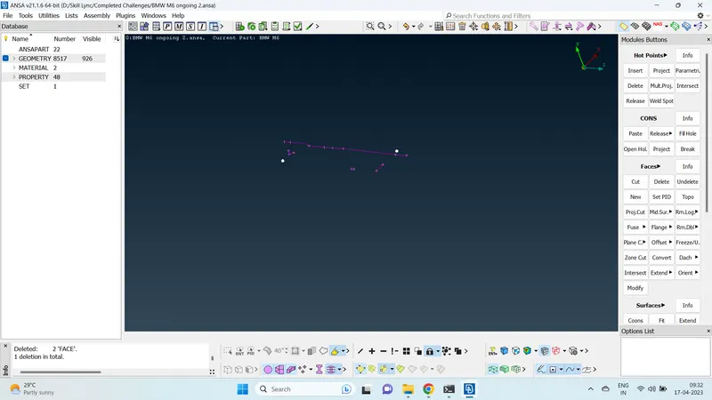
- Once the entire geometry is cleaned up. we can check for errors.
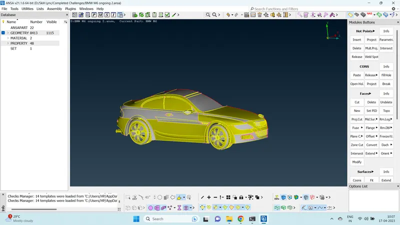
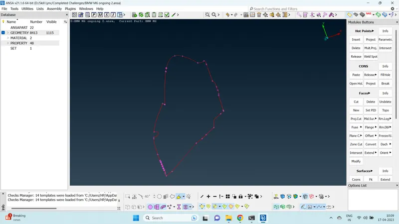
- Make sure only the intended single cons are present in the geometry.
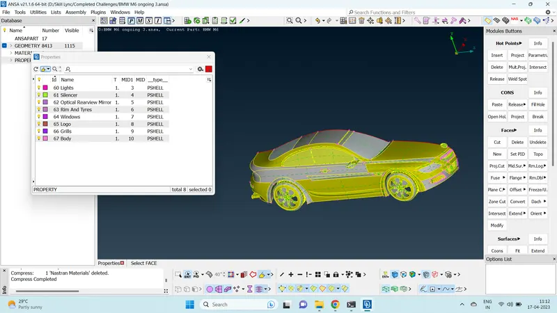
- Once the clean up is done, we can start assigning PIDs to various parts of the geometry.
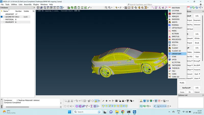
- You can choose the solver in which you are going to do CFD analysis in the decks.
- There are lot of quality criteria available for selection.
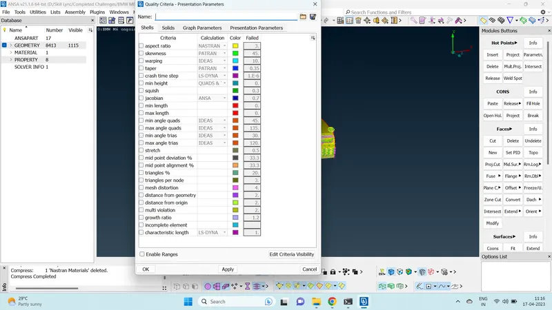
- We can choose only the required quality criteria by choosing the edit criteria visibility and selecting only the required ones. We can also choose the solver, color and failed criteria as below.
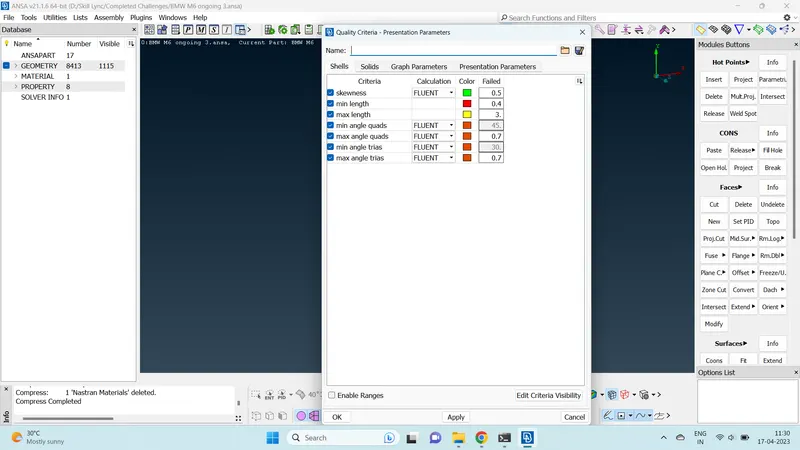
- Once we set the quality criteria, our next task is to check the geometry for minimum and maximum length.
- The target length of each PID is given, we can seperate the PIDs and see what can be the minimum length and maximum length criteria that can be given to the PIDs.
- Measure tool can be used to measure the distances between cons and nodes.
- For example, the target length of logo is 1 mm. we can use measure tool to measure various distance between two cons to find out the minimum length.
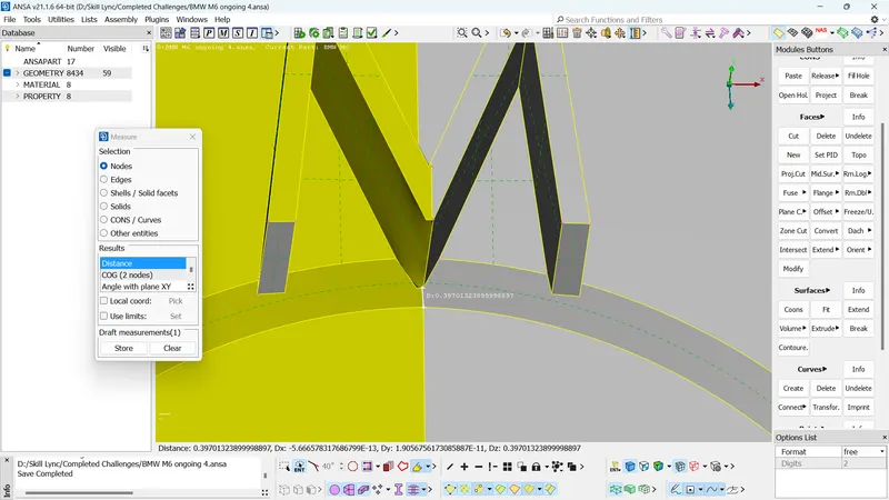
- The store option in measure tool can be used to save the measured distance so that we can use the same for future reference. It can also be hidden by deselecting the measurement option in the database.
- Similarly, check for all the PIDs about what the minimum length can be kept for the PID with their respective target length. Check all surfaces to see of the minimum target length will fail. You can remove unnecessary cuts and hot points which may result in the failure of minimum length quality criteria.
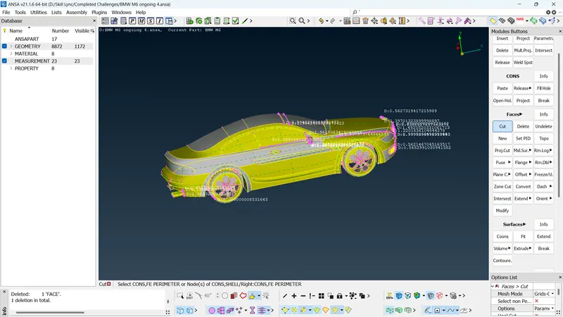
- Once you have figured out the minimum length of each PID and made necessary modification to meet the quality criteria, we can move onto the surface meshing.
- Isolate the PIDs that are not shared with any other PIDs and start surface meshing.
- Update the quality criteria, mesh parameter and length function based on the respective PID's quality criteria.
- You can use spot mesh>visible to generate mesh.
- Once mesh is generated, you can use hidden mode in drawing styles to see the off elements.
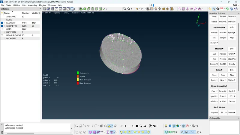
- You can see the off elements highlighted by their respective colour.
- You can use shell mesh>reconstruct>visible to reduce the number of off elements.
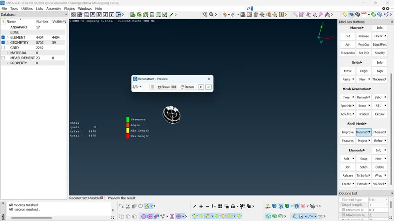
- Once all the off elements are rectified, you can move to the next PID.
- If off elements still exist after mesh reconstruction, you can use various tools in mesh module to rectify the problem.
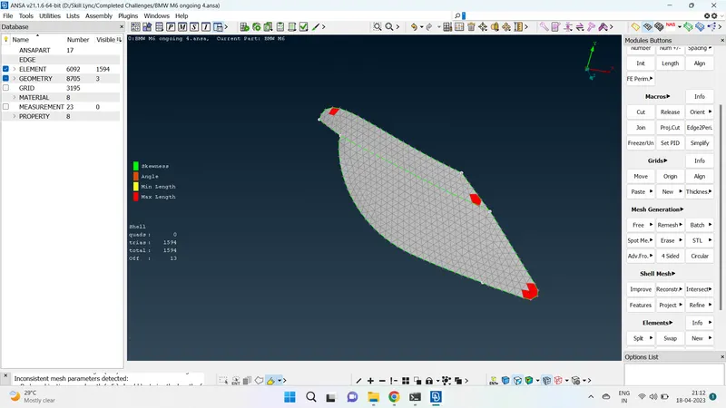
- Mesh module>grids>move function can be used to adjust the mesh element. By moving the nodes of the mesh element, we can arrive at such locations for the node such that the mesh element meets the quality criteria.
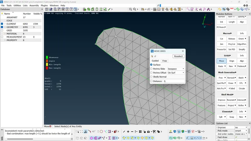
- The move function is effectively used to rearrange the nodes of the mesh elements to meet the quality criteria.
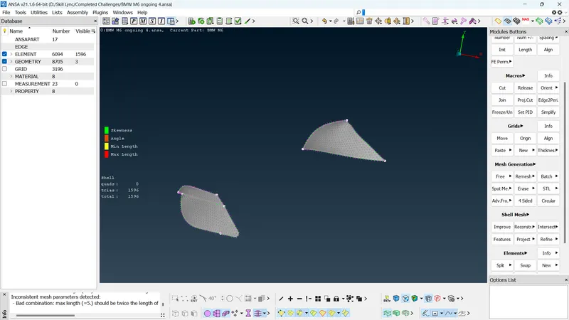
- Similarly, move to the next PIDs for surface meshing with their own respective quality criteria.
- In the case of body PID, since it is shared by other PIDs, while updating the length function, deselect the cons which are shared by the other PIDs so that when meshing is done, surfaces or cons which do not fall into this criteria do not get their mesh erased.
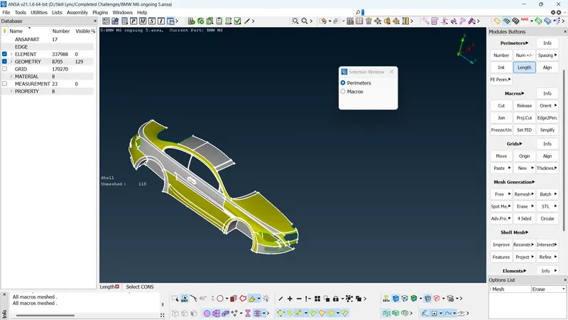
- Once this is done, we can move onto the surface meshing. Make sure to clean up the off elements after surface meshing.
- Once all the PIDs are surface meshed and rid of off elements, we can move onto the next steps.
- Make sure there are no unmeshed macros in the geometry after all the PIDs are meshed.
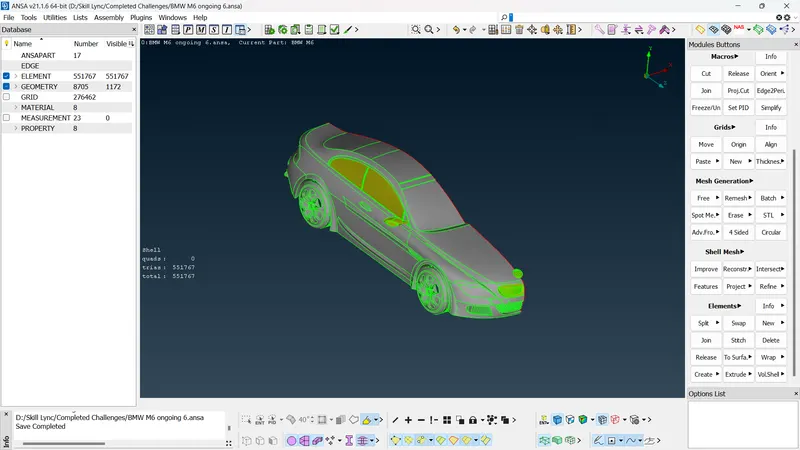
- Once all the surfaces are properly meshed, we can apply symmetry to the geometry.
- Transfer>Copy>enity : Select the entities you want to do symmetry on. Deselect logo since we don't want to do symmetry on that.
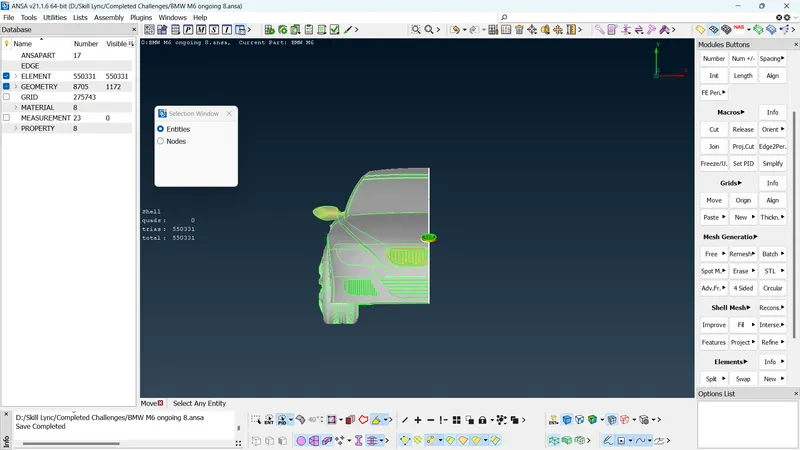
- Middle click>symmetry>3 point plane. select the 3 reference points. Middle click after that.
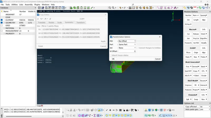
- Select no offset and click ok. After that click finish. You will have the whole car.
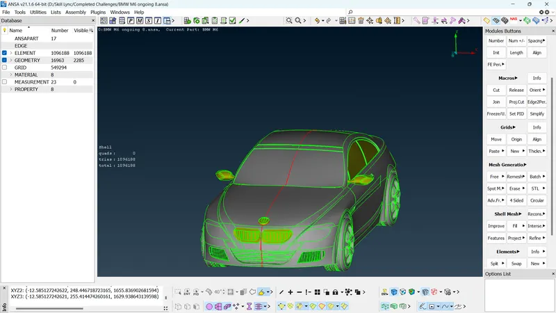
- Once symmetry is done, check for the presence of single cons and do necessary operatrions to fix them. Paste option in TOPO mode can be used to paste together two very close cons.
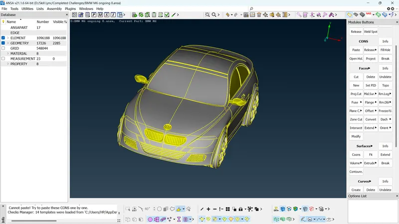
- Check for any single cons and unmeshed macros. once this is done we can move onto create wind tunnel.
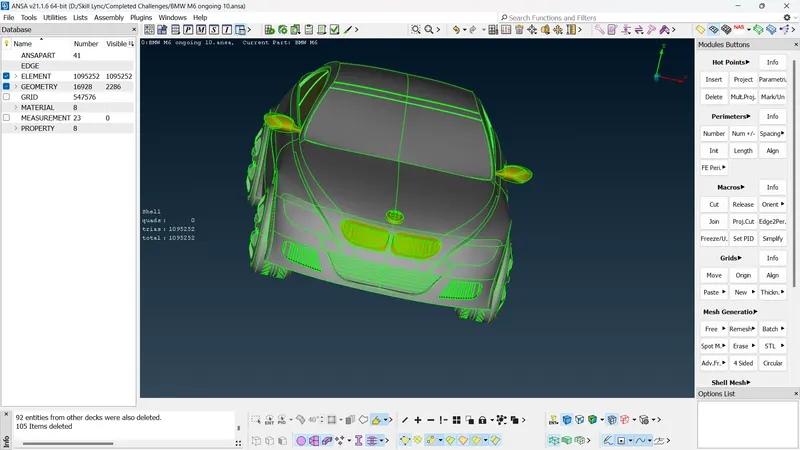
- The wind tunnel can be created in TOPO mode.
- The wind tunnel should have a distance of 4 times the model towards front, 6 times the model towards back, 1 times the model towards side, minimum possible distance towards bottom and 3 times the model towards top.
- Our model 1300 mm long.
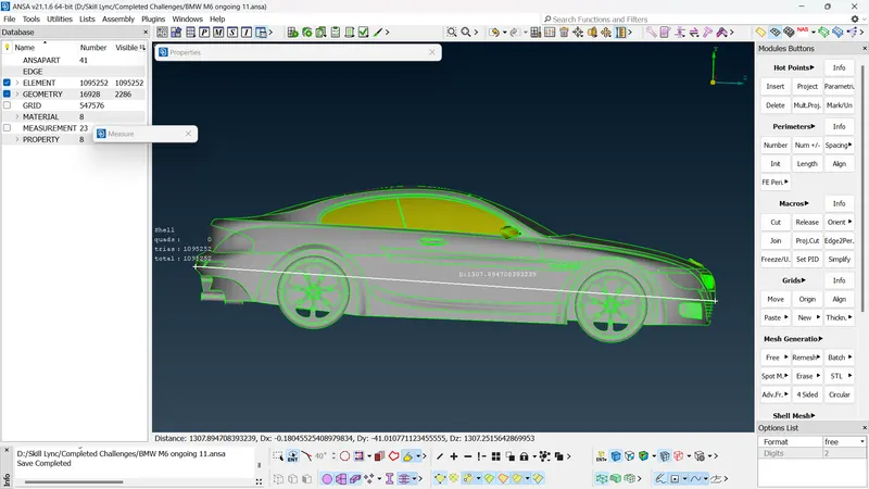
- Based on this the wind tunnel can be created.
- TOPO>Points>Relative function to create a point relative to another. Specify the distance you want the point to be created relative to it on the axis.
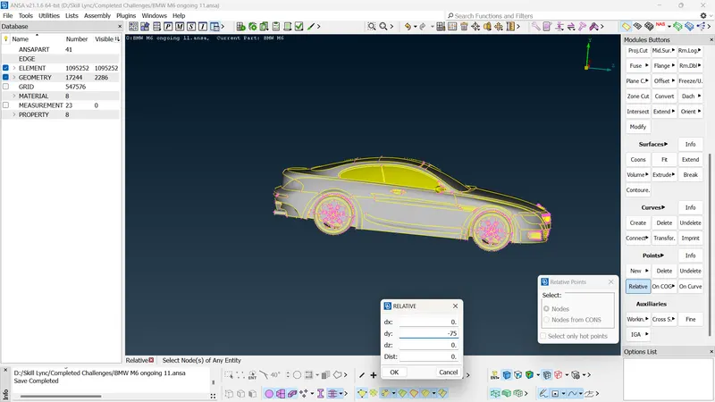
- Similarly you can create other points for the bottom surface of the wind tunnel taking into account the length of the car from which the first point was created.
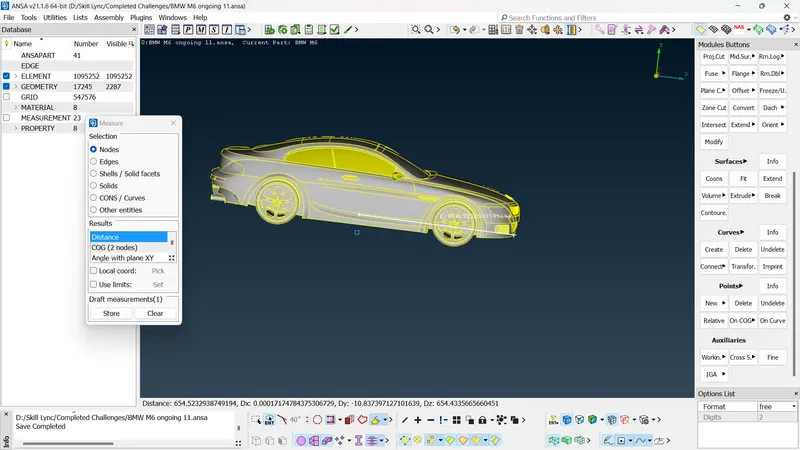
- Once the required points are created, you can create curves.
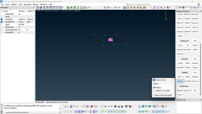
- TOPO>Curves>create function can be used to creat curves from points.
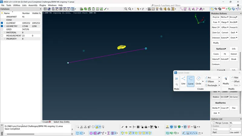
- These curves can be used to create surfaces.
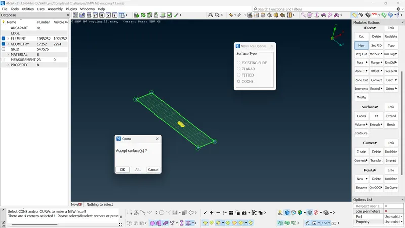
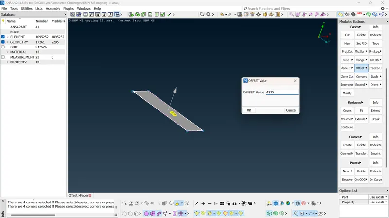
- TOPO>Faces>Offset>face function can be used to offset the created plane to the top.
- These two faces can be used to create rest of the surfaces of the wind tunnel.
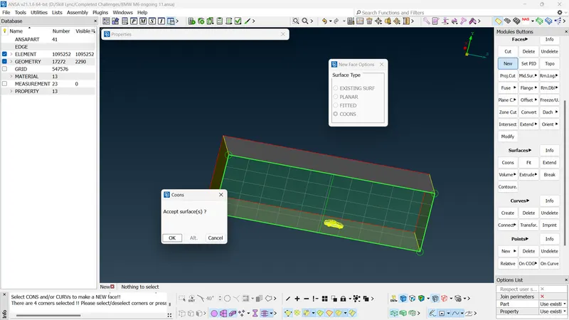
- Once tunnel is created, assign appropriate PIDs to the tunnel.
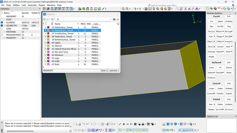
- We can start meshing of the tunnel. The top surface can have a mesh length of 100 mm and the bottom surface can have a mesh length of 20 mm. Since the are near the car is more significant, we have done so. Mesh the top and bottom surface with their respective mesh length.
- Since our area of intrest is near the car, we need finer mesh near the car and coarser mesh as we move away from the car.
- We can use mesh>perimeter>spacing function to incremetally increase the size from bottom to top.
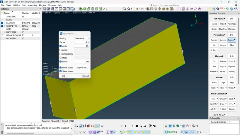
- Once this is done, We can move onto meshing og the faces.
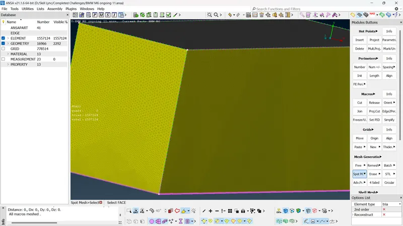
- Once all the surfaces are meshed, we can move onto the volumetric meshing module.
- Volumetric mesh module>volumes>define>autodetect function can be used to detect the volumes.
- We require only the volume between the car and the wind tunnel for analysis. So, every other volumes can be deleted.
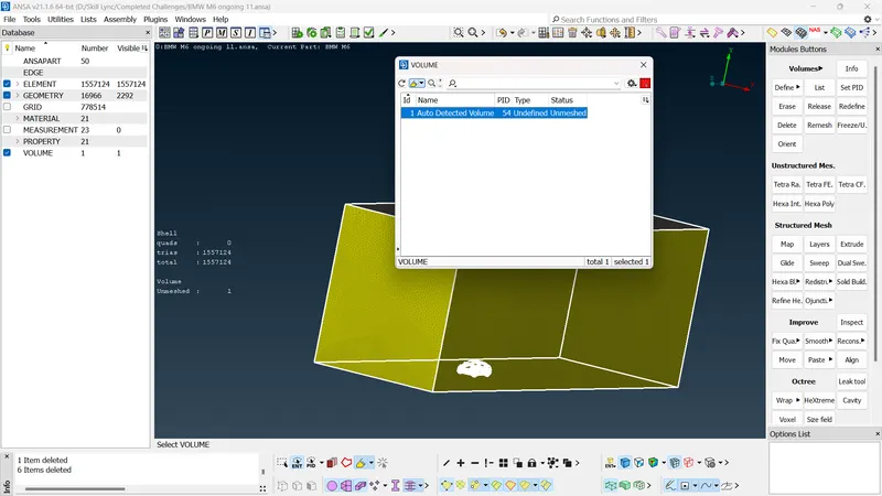
- The required volume can be volumetric meshed by righ click>remesh.
Results
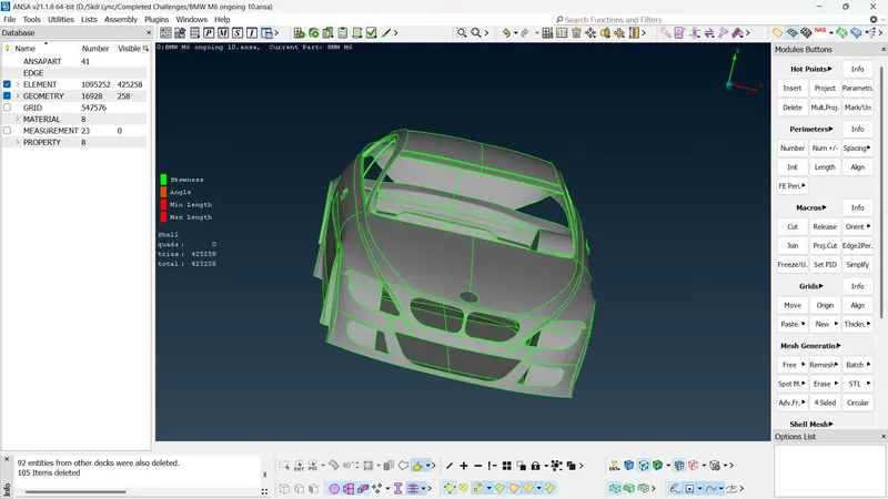
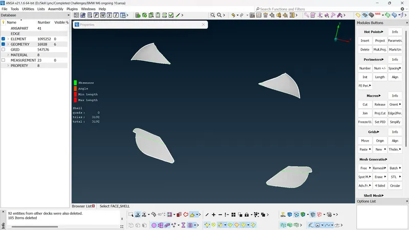
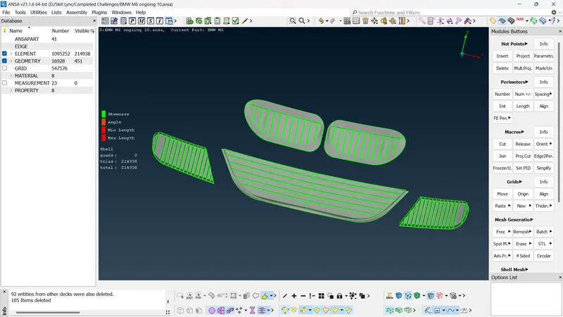
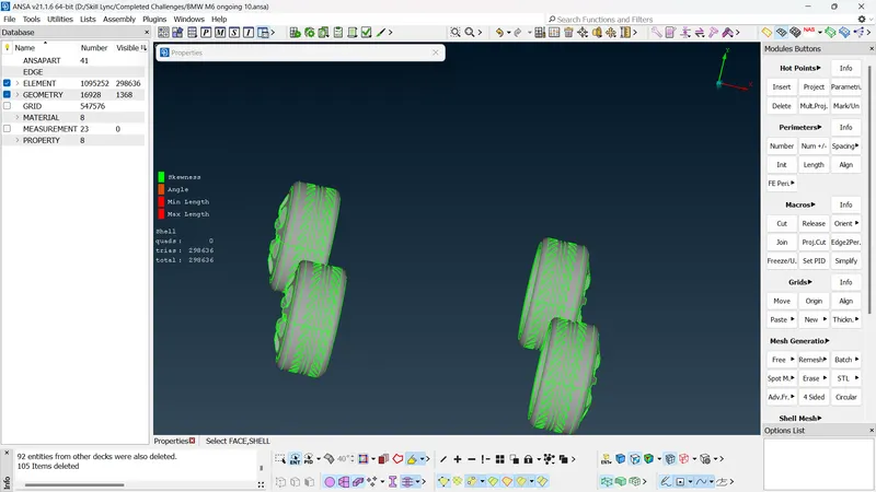
- The geometry was meshed with tria mesh element and their respective mesh length.
- The body PID was meshed with 3 mm target length, 0.8 mm minimum length and 5 mm maximum length with zero off elements.
- The Light PID was meshed with 4 mm target length, 3 mm minimum length and 5 mm maximum length with zero off elements.
- The grills PID was meshed with 1 mm target length, 0.3 mm minimum length and 2 mm maximum length with zero off elements.
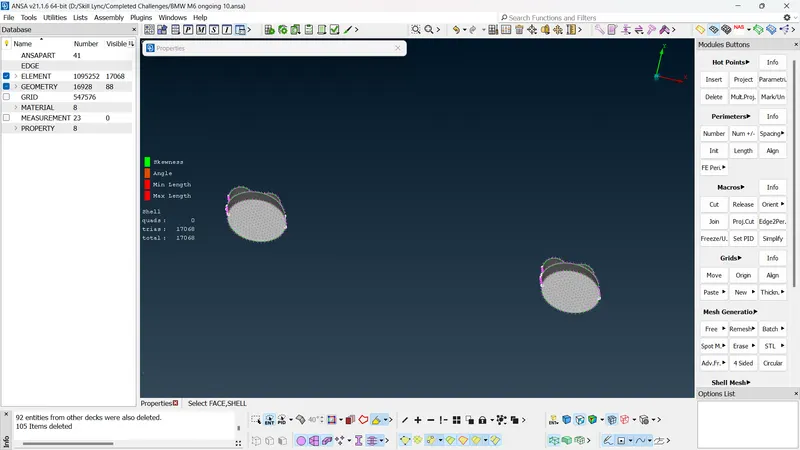
- The rims and tyres PID were meshed with 2 mm taget length, 1 mm minimum length and 3 mm maximum length with zero off elements.
- The Optical rear view mirror PID were meshed with 2 mm taget length, 1 mm minimum length and 3 mm maximum length with zero off elements.
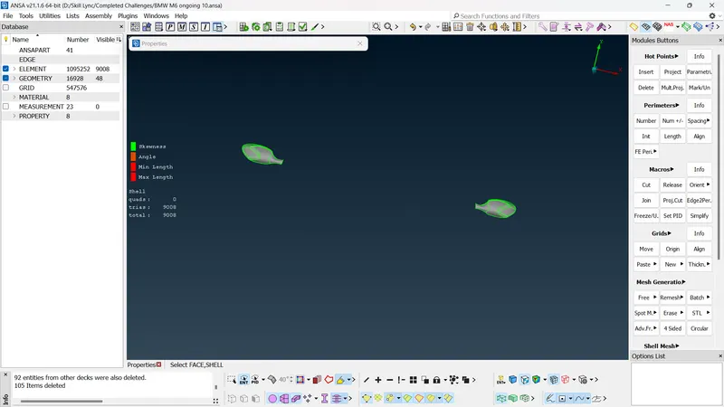
- The windows PID were meshed with 2 mm taget length, 1 mm minimum length and 3 mm maximum length with zero off elements.
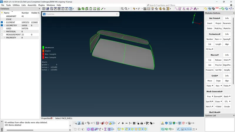
- The Silencer PID were meshed with 3 mm taget length, 1 mm minimum length and 4 mm maximum length with zero off elements.
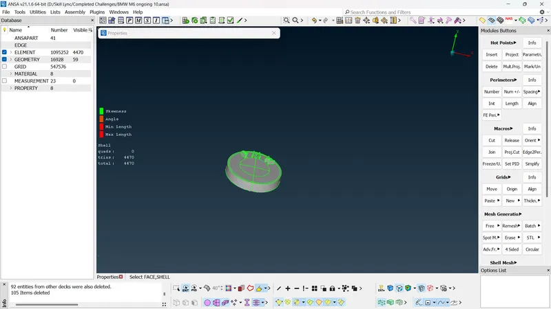
- The logo PID were meshed with 1 mm taget length, 0.3 mm minimum length and 2 mm maximum length with zero off elements.
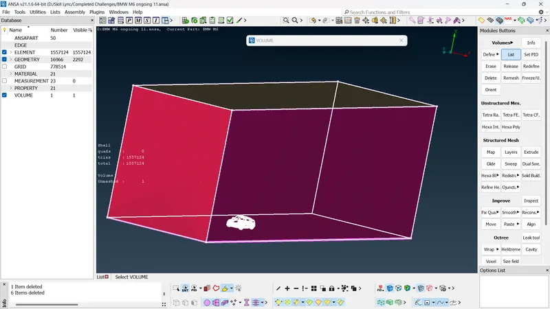
- The wind tunnel was created with the given criteria and meshed accordingly.
- Proper volume was selected for volumteric meshing and unwanted volumes were deleted.
Outcomes
- Got familiarized with various topo module function.
- How to clean up geometry based on the significance of the parts.
- unwanted parts which do not have any significance to the analysis like structures inside the body while dong outside analysis of the body can be deleted to save computational time.
- How to mesh inidividual parts of the geometry based on their significance and size.
- How to reectify off elements which do not meet the quality criteria of the mesh.
- How to create volumes such that they become a common volume while doing volumetric meshing and can be deleted if they are not significant.
Download Link For geometry
https://drive.google.com/file/d/1Ysfr3TcsizM6oj8_Plj0BAdOQWLxlqr3/view?usp=sharing