Week 3 Challenge : CFD meshing on Turbocharger
Aim
To perform geometrical checks on the given model and do the necessary surface clean up. Assign appropriate PID to the parts and do surface meshing with the given mesh length for each components. Do volumetric meshing in the necessary volumes obtained.
Procedure
- Import the geometry file into the ANSA software by file>Open> downloaded file.
- Once the geometry is opened, geometrical checks are performed on the geometry.
- The errors that pop up in the geometrical checks have to rectified before moving onto further steps.
- Only after surface clean up can we do surface meshing and then move onto the volumetric meshing.
- While opening the geometry, lot of glitching on the surface can be seen. This indicates overlapped surfaces. Carefully delete unwanted overlapped surface and retain the required surface
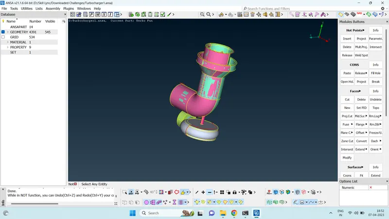
- Faces>TOPO function can be used to join cons. 3 single cons will be joined to form one triple con and 2 single cons will be joined to form double con.
- Extended surfaces in the geometry can be deleted. If required surfaces also get deleted with the extended surface. Faces>New option can be used to create the required surface.
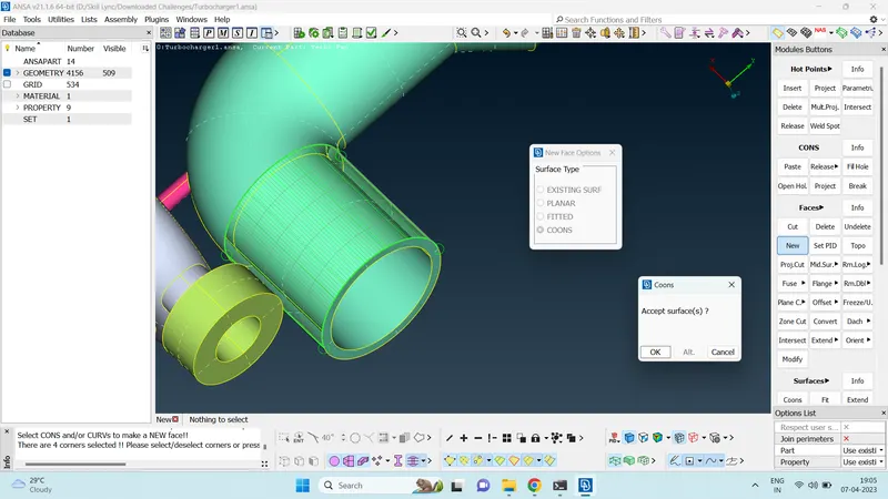
- Sometimes, creating surfaces using new function may create surface in an unrequired way.
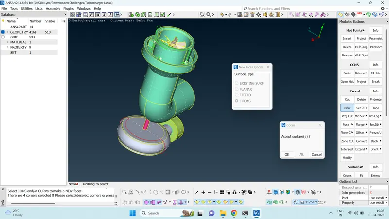
- In such cases, hot points can be projected on to CONS as required to create surfaces in the required way.
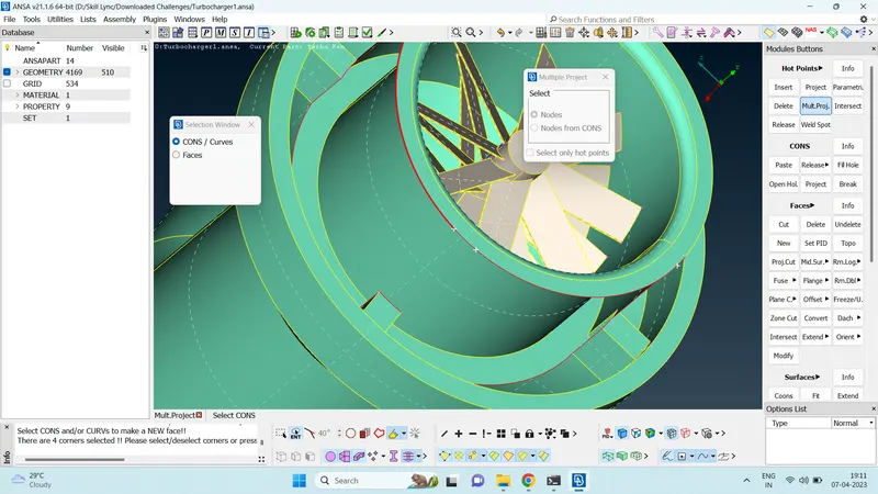
- These hot points can be used as reference to create the required surface.
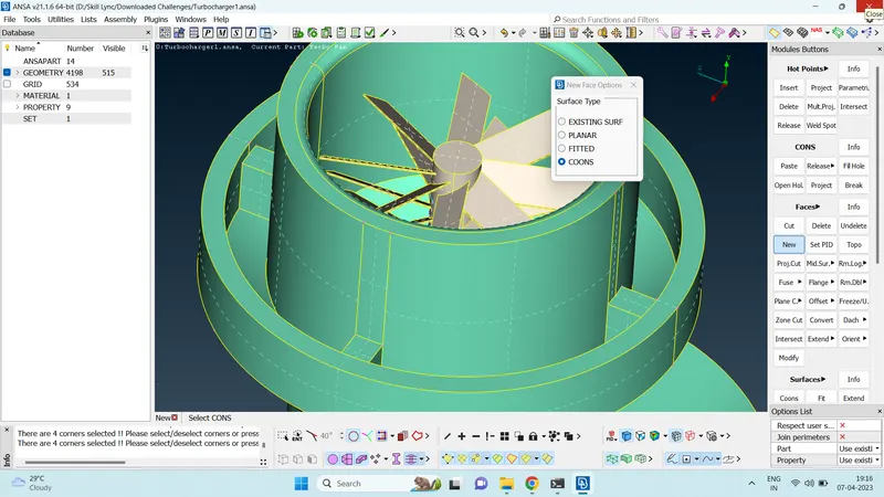
- Sometimes intersected surfaces can exist which cannot be deleted using delete function.
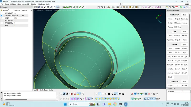
- In such cases, Faces> intersect function can be used to create cons at the intersection of two surfaces.
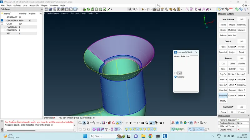
- Once the cons are created, the extended intersected surfaces can be deleted using the delete function.
- The cleaned up PID can be hidden using the property manager so that we can work on the other PIDs very easily.
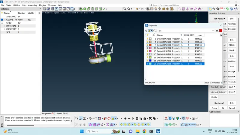
- Some of the triple cons fromed may actually be required. Ensure that such triple cons are required using various boolean operation.
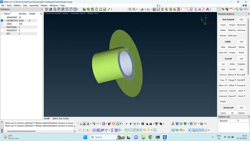
- Creating surfaces directly using FACES>NEW>COONS on the bottom casing is giving some unwanted surfaces.
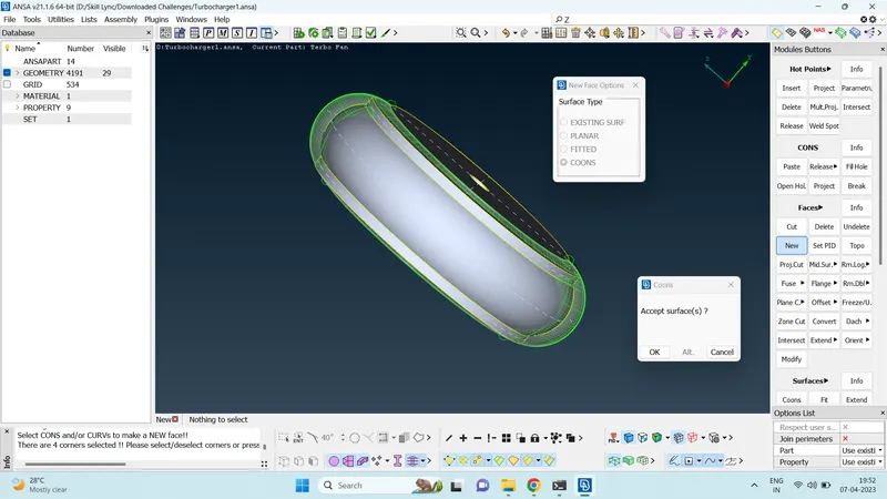
- In this case also we can create hot points on the cons to create a more well defined surface using those inserted hot points as the reference points for surface creation.
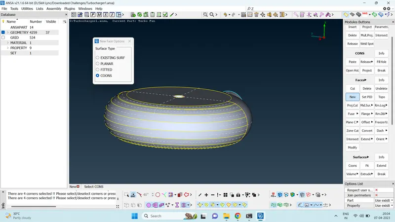
- In case such as below, it is not possible to delete overlapped surfaces without deleting the required geometry. In such cases, CONS> Project option can be used to project cons of one surface onto another surface. Doing so helps in seperating geometry at the overlapped surfaces.
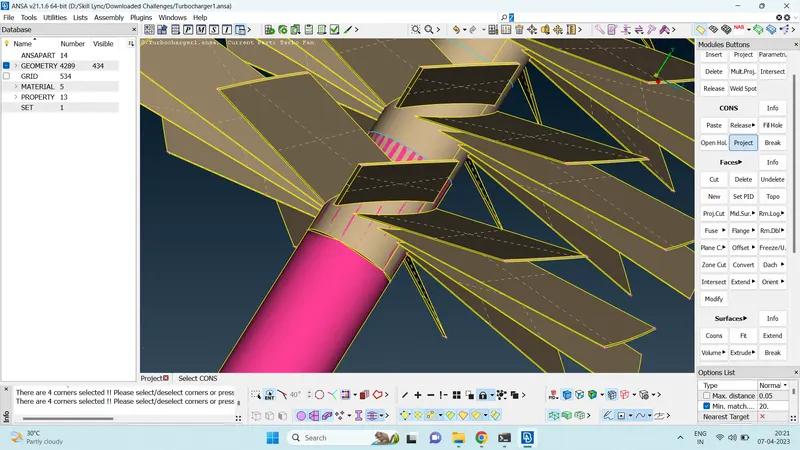
- After performing project con function, the overlapped surface can be deleted easily using delete function.
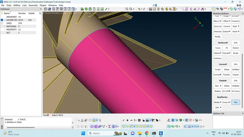
- Sometimes deleting surfaces create poor definition of geometry.
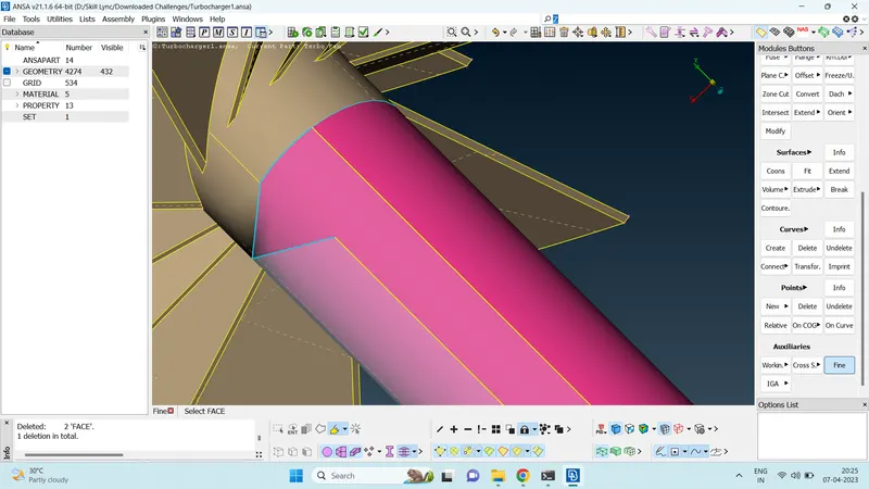
- In such cases, Auxilaries>fine option can be used to increase the defintion of the geometry.
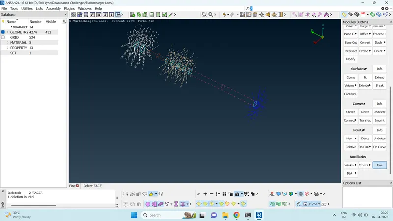
- Deselect single con, double con and shadow mode to view if there is any triple con present.
- Use boolean operation effectively to check for overlapped surface and delete if any overlapped surface is present.
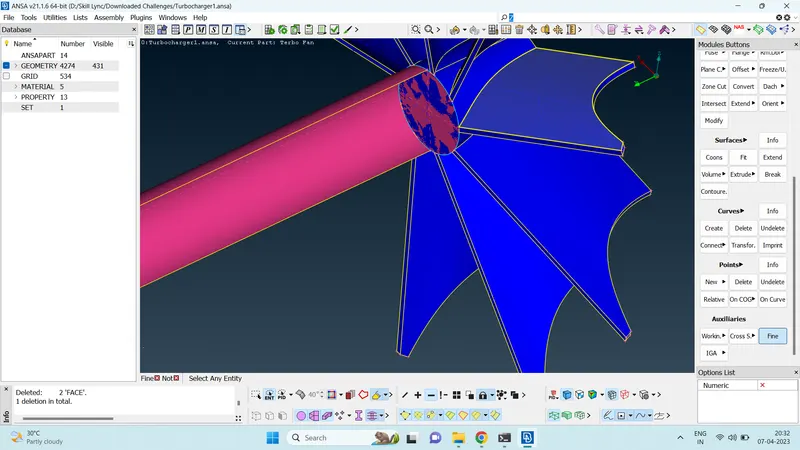
- Sometimes when deleting surfaces, Triple cons or overlapped double con and single can come to exist. In such cases use CONS>Release function to release these cons and use TOPO function to join these cons again in an appropriate manner.
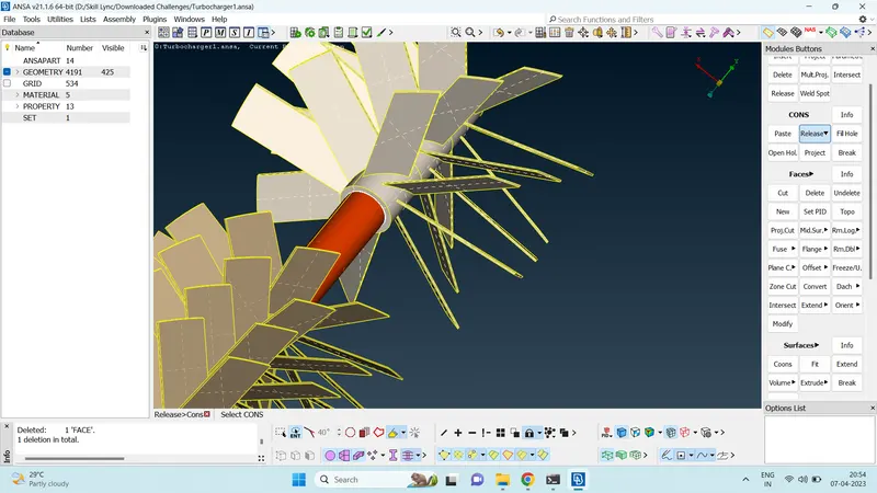
- Once all triple cons, single cons and overlapped surfaces are corrected, Check for the same using boolean operations and wireframe mode.
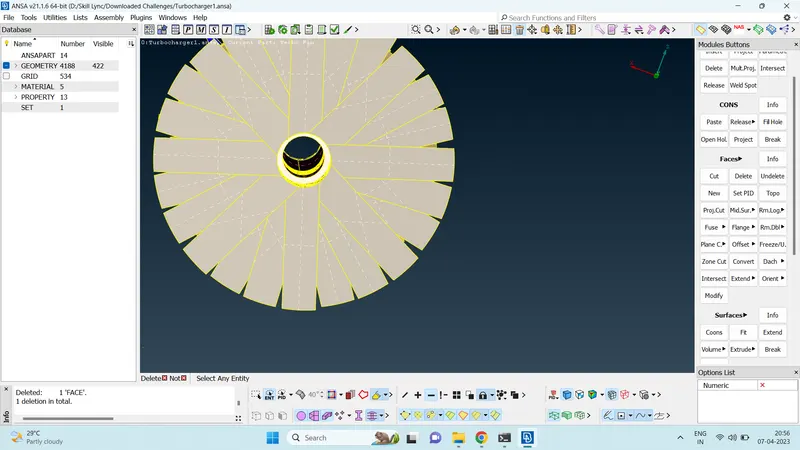
- Once all part of the geometry has been cleaned up. We can start assigning PIDs to each individual parts of the geometry.
- Compress option can be used to delete any unassigned PIDs which cannot be directly deleted in the property manager.
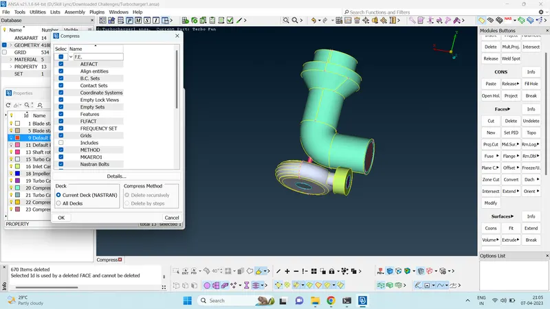
- All parts of the geometry are assigned their individual PIDs.
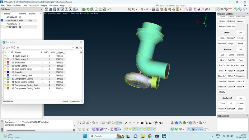
- Ensure that all part of the geometry are properly closed so that we ca do volumetric meshing and cfd analysis properly.
- Once the surface is cleaned up properly, we can move onto the mesh module.
- Different parts of the geometry have different mesh length. This has to be assigned respectively.
- Compressor casing, compressor casing inlet, compressor casing oulet, turbo casing, turbo casing inlet, turbo casing outlet and inlet cover have 5 mm as mesh lenght.
- Use propert manager to hide other parts of the geometry except the above mentioned ones.
- Update the mesh parameter.
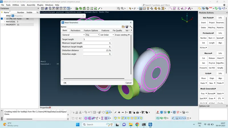
- Update quality criteria.
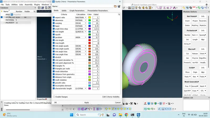
- Update Length in perimeter>Length>perimeter and macros.
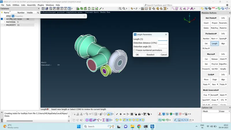
- Once these are done you can use spot mesh> visible function to mesh the visible geometry.
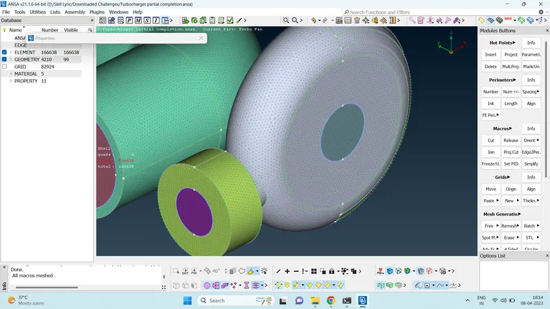
- Use measure tool and boolean operations to ensure that all parts of the geometry is meshed using the required quality criteria.
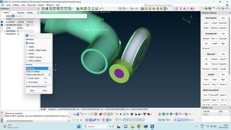
- Similarly, mesh the other parts of the geometry using the required quality criteria.
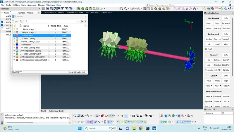
- It is observed that while meshing, some surfaces of the geometry gets unmeshed when adjacent surface are shared. This is due to two different quality criteria being given to the same cons shared by two different surfaces.
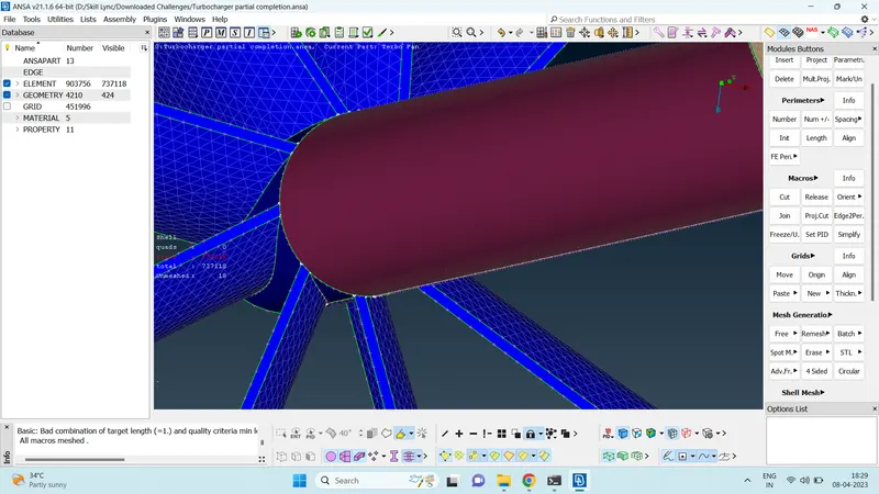
- In such cases, the length option can be updated with a range so that near the shared con, the surfaces gets meshed with a mesh length which is within a range of the quality criteria give to the neighbouring surfaces. The mesh elements near to the shared con will have mesh length within this range and as we move further away from the shared con, the mesh elements will stick to the given quality criteria of the surface.
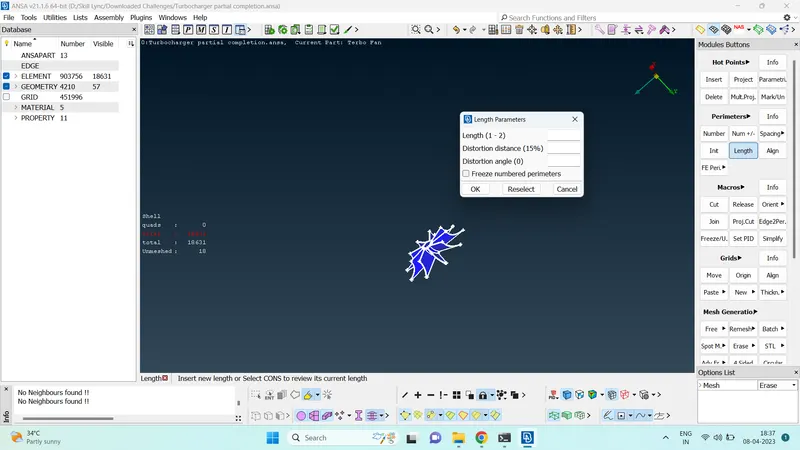
- Ensure that all surfaces of the geometry are meshed before moving onto the volumetric meshing module. This can be confirmed on the left side of the screen under shell. After making visible all parts of the geometry, if there are any unmeshed surface, it will show up under the shell statistics on the left side of the screen.
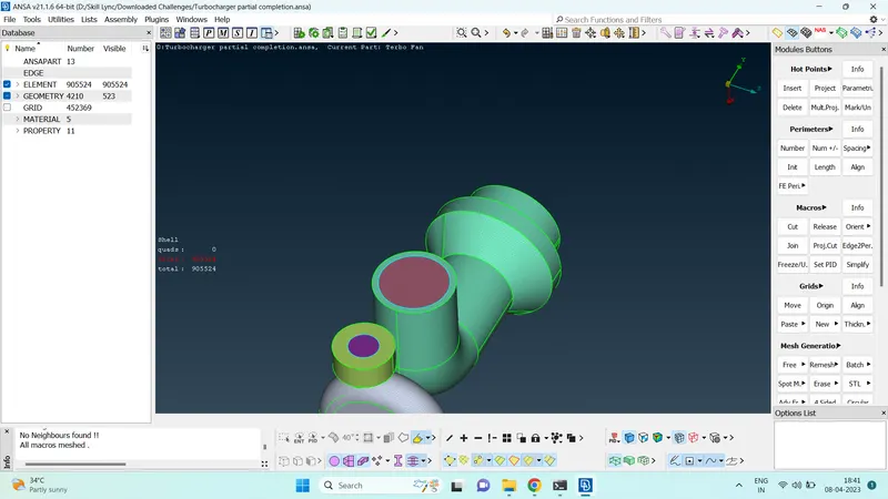
- Once the geometry is surface meshed, we can move onto volumetric meshing module.
- In volumetric module, volume>define>autodetect function can be used to auto detect the volumes in the geometry.
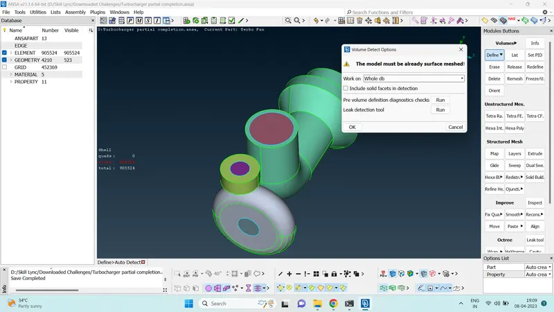
- There are 8 volumes detected. Clicking on the detected volumes will highlight the volumes.
- Material volume is also detected.
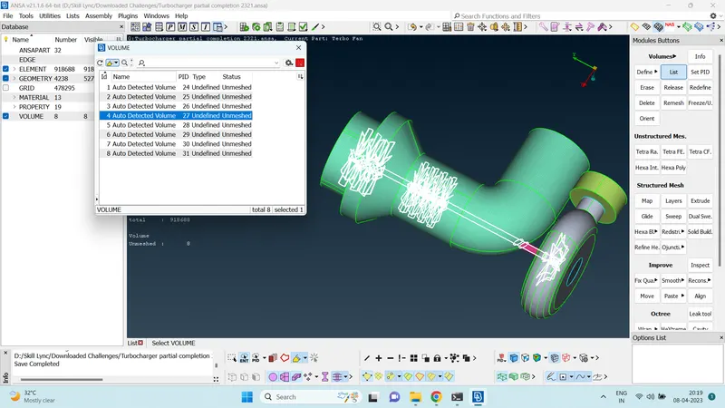
- Only keep the volumes where fluid flow is expected and delete the rest of the material volumes.
- Once the unwanted volumes are deleted, we can move onto the volumetric meshing.
- In volume list, right click the volume you want to mesh. In the dialogue box click remesh.
- In Remesh, the program will ask volume type. We can give Tetra CFD as the volume type.
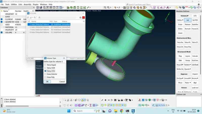
- Once the volume is meshed, the Status in the volume list will be changed to meshed and the type will be changed to Tetra CFD.
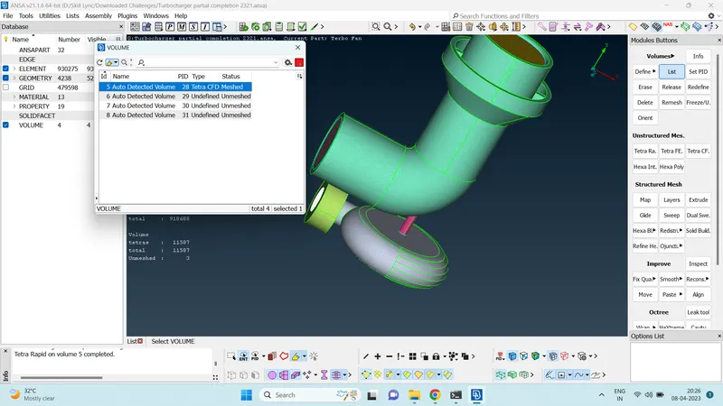
- Similarly do the volumetric meshing for the remaining volumes.
- Once all the volumes are meshed using volumteric meshing, the meshed volumes can be observed.
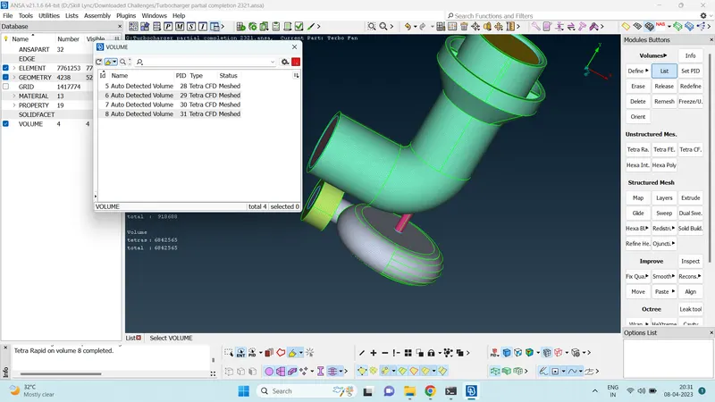
- The meshed volume can be seen in the topo module by deselecting geomerty and FE mode.
Result
- The given geometry was cleaned up using various TOPO module tools.
- After the geometry clean up, the surfaces were meshed in the mesh module.
- Once surface meshing was completed, the fluid flowing volumes of the geometry was volume meshed.
- The meshed volume can be seen in TOPO module by deselecting geometry and FE mode.
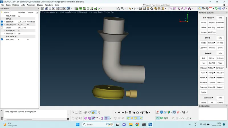
- The cross section of the volume meshed can be seen using boolean operations.
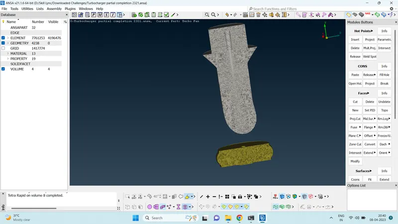
- It is observed that volumetric mesh is very fine closer to blades and the mesh elements gain size as we move away from the blades and shaft.
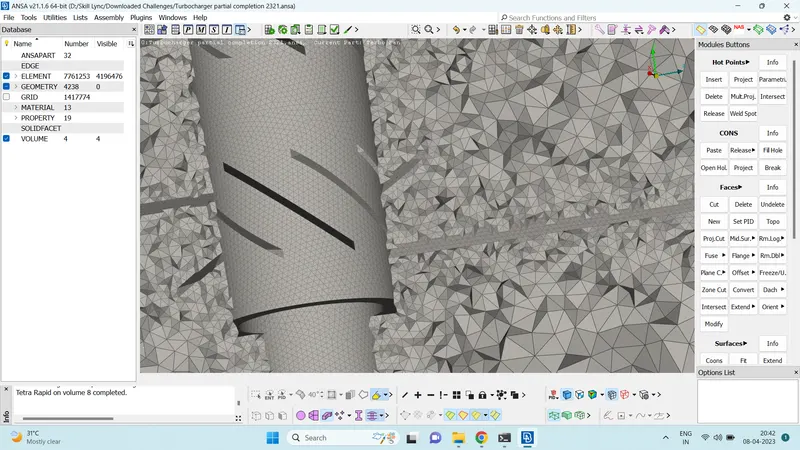
- This is due to the fact that volumetric mesh element length is defined by the surface mesh element length. The blades and rotor have small mesh element length; so the volumetric mesh elements near them is also small. The casings have large mesh element length; so the volumetric mesh length also increases as we move away from the blades and closer to the casings.
Outcomes
- Understood the working of various TOPO clean up tools.
- Learned to use boolean operations effectively.
- Learned to give independent surface mesh length to various parts of the geometry.
- It is advisable to vary the mesh length based on the part of the geometry. Important parts can be given finer mesh length and bigger parts can be given larger mesh length to save computational time.
- Learned to do volumetric meeshing. The volumetric mesh element length is dependent on the surface mesh length. So it is advisable to do surface meshing properly and change the size of the surface mesh whereever good capturing of results is required.
Download Link Of Meshed Geometry
https://drive.google.com/file/d/11JbfhZSC_W0VtQPBZshKrNMShgx8TJGV/view?usp=share_link