Week 2 Challenge : Surface meshing on a Pressure valve
AIM
To clean up the given geometry of the pressure valve and mesh the geometry using 3 different mesh length with tria as the mesh element.
Procedure
- To work on the geometry, import the file into the ANSA software by clicking file>open>choosing the location where the geometry is saved.
- Once the geometry is imported, the sufaces have to be cleaned up in the TOPO module before the meshing process can begin.
- Geometrical checks can be performed by clicking checks>geometry>errors you want to check>execute.
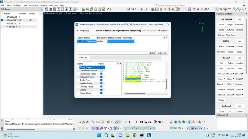
- Once executed, the software shows the errors, if any.
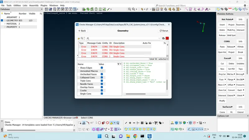
- These errors have to be corrected before we can move onto the meshing.
- Clicking on the errors will highlight the error on the geometry.
- For doing CFD analysis, there cannot be single cons present, they have to be cleaned up.
- Single cons can be viewed in the wireframe mode by unselecting cross hatch, double cons and triple cons and deselecting the shadow mode.
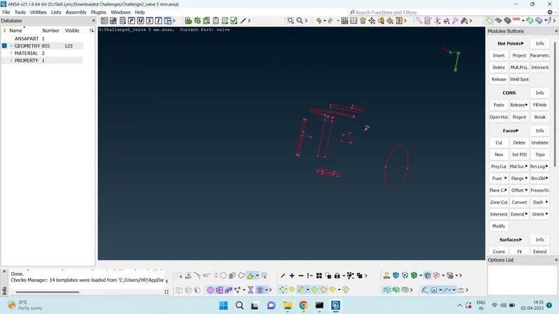
- New surfaces can be created from single cons by using new tool in the faces toolbox. Any of the four algorithms can be used to create new surfaces based on the location of the single cons and adjacent surfaces.
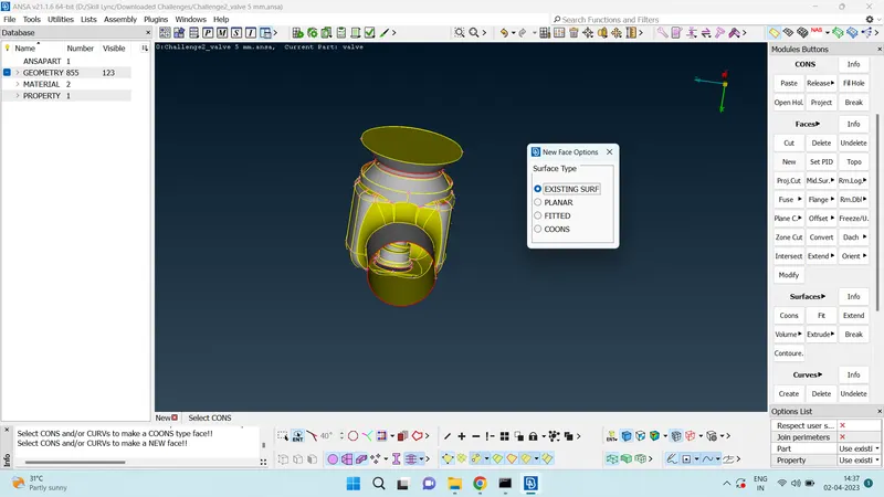
- Exisitng surface algorithm can be used to create a new surface on an already existing surface.
- Fitted algorithm can be used to create a new surface inside a loop of cons. The loop selection can be used to select cons which form a loop instead of selecting individual cons.
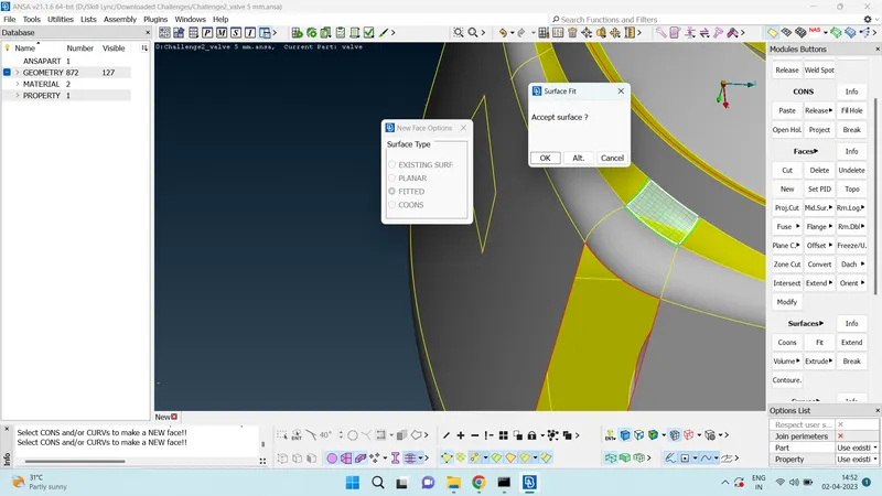
- Fill hole option in cons toolbar can be used to fill circular spaces.
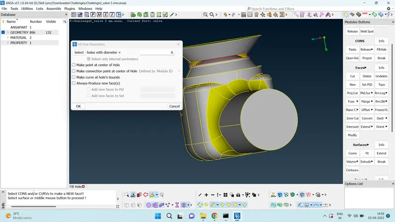
- COONS alogirithm is similar to fitted algorithm. It creates a surface inside the selected cons.
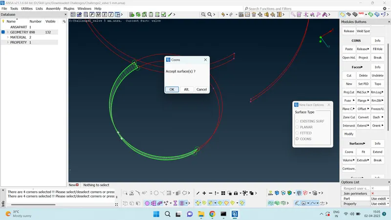
- It is advisable to always have closed geometry while doing cfd meshing.
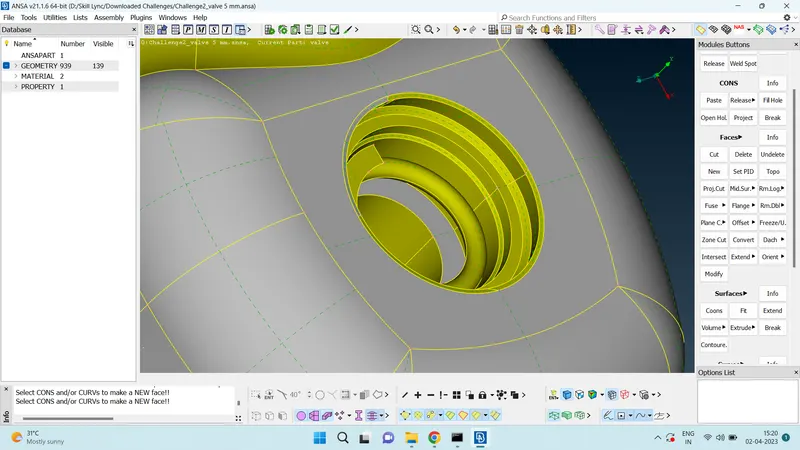
- Surfaces can be created from double cons also using the same algorithms for single con.
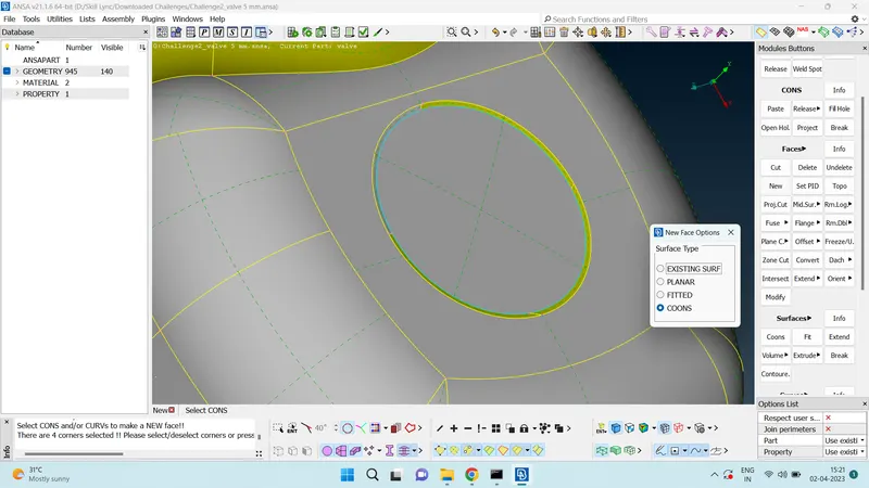
- Do the checks again for the geometry and see if error still exist. If error for triple con exist, ensure that the present triple con is actually required for the geometry.
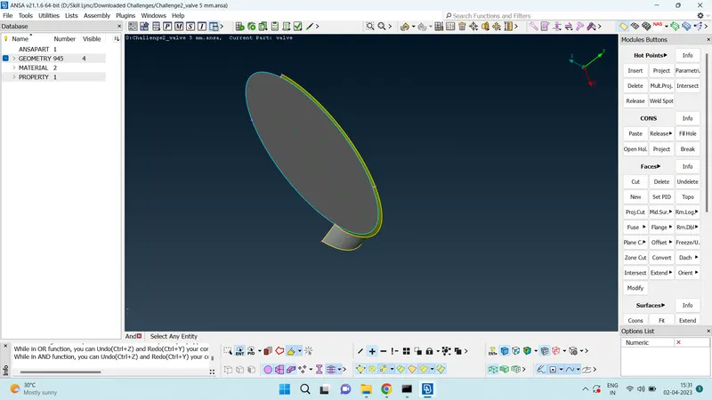
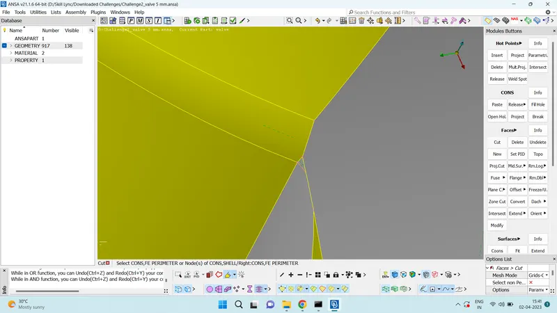
- Once the surface cleanup is done, cons of smaller surfaces can be deleted so that they merge with bigger surface. This helps in the quality of the meshing. This can be done using the cut option in the faces toolbox. select the cut option and right click using mouse on the cons you want to delete.
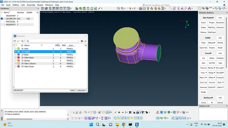
- Once the clean up is completed. Each parts can be named individually. This is done in the property manager. Property manager>Right click>New>PSHELL>PSHELL>name of the part.
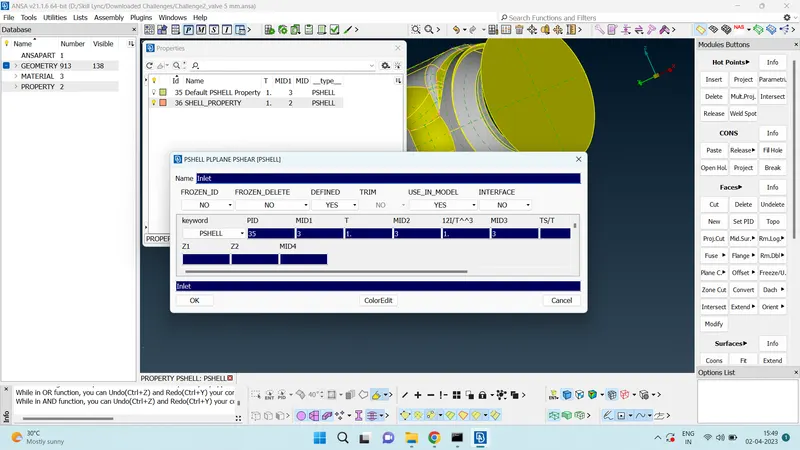
- Once the PID is created, it can be assigned to the geomerty part by PID>Right click>apply>cross hatch on part to be assigned.
- Various colours can be given to the assigned PID by double clicking on the colour square of the PID Name.
- Once all the parts are assigned their individual PID name. We can delete the parent PID name which is not assigned to any part of the geomerty. The bulb indicates whether the assigned PID is visible or not. Partially lit bulb indicates only part of the geometry is visible. Pick option in property manager can be used to highlight the name of the PID using selected part and vice versa. Boolean operations help in accurately selecting the parts.
- Once each part is individually assigned their PID, We can move to meshing module.
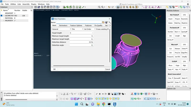
- For 5 mm mesh length, in mesh parameter, keep target length as 5 mm, minimum length as 4 mm, maximum length as 6 mm, element type as tria.
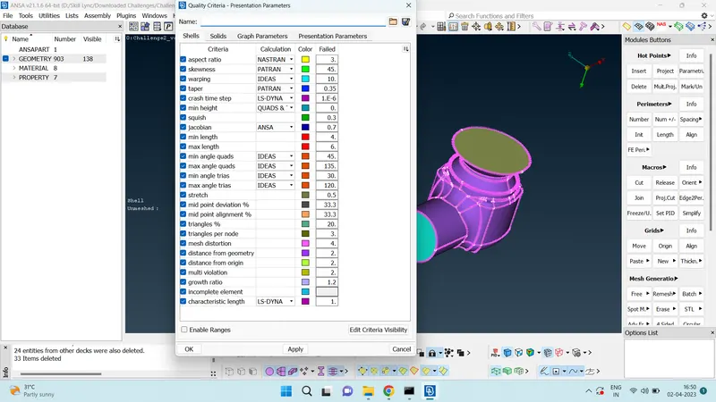
- In quality criteria, we can keep min length as 4 mm and maximum length as 6 mm.
- In Length function in perimeter tool box, keep perimeter as 5 mm and macros as 5 mm.
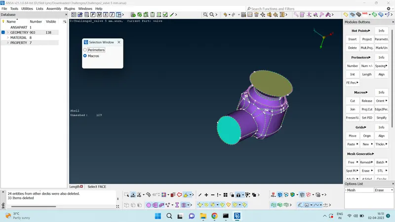
- Once these steps are completed, we can move onto the meshing part.
- To easily mesh the geometry, Only make visible the part you want to mesh and give spot mesh to visible entity in mesh generation. Do it for all all PIDs of the geometry.
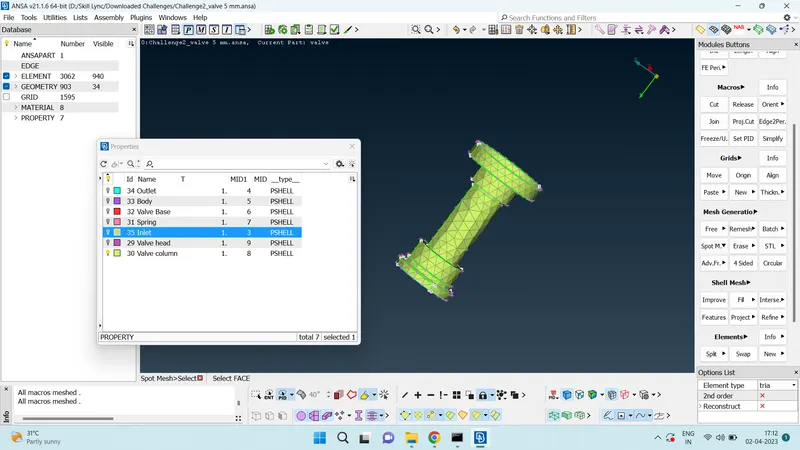
- Once the process is done. Repeat the steps for 3 mm mesh length and 1 mm mesh length.
Result
5 mm
While using the 5 mm mesh length, the surfaces of some part of the geometry has very poor mesh quality, since the mesh length is big for the given geometry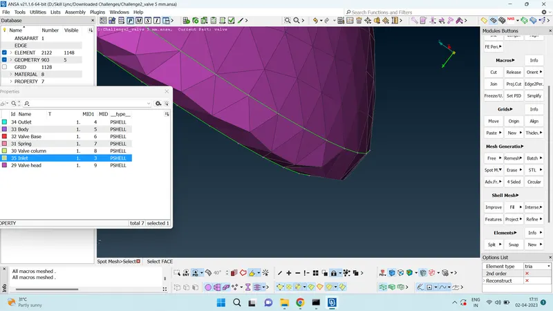
Also for parts whose dia is lower than the mesh length, the geomerty appears to be two dimensional and not of the expected quality. 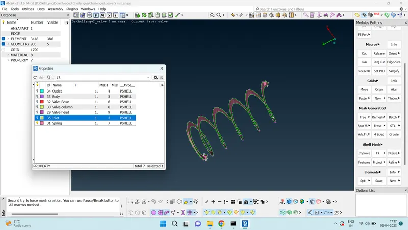
3 mm
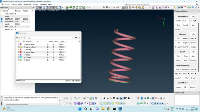
While using 3 mm as the target length, the quality of the surface improved. But still there were some distortion.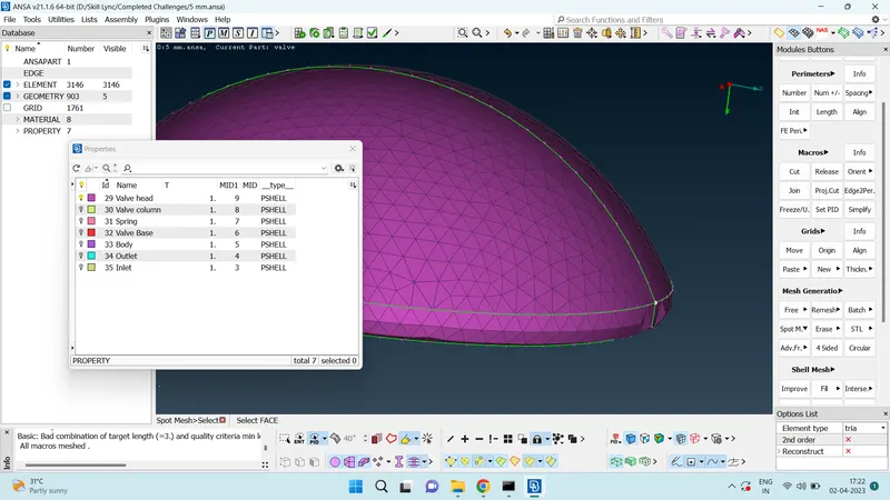
Spring achieved a three dimensional geometry with 3 mm length, but still the quality of the surface was poor.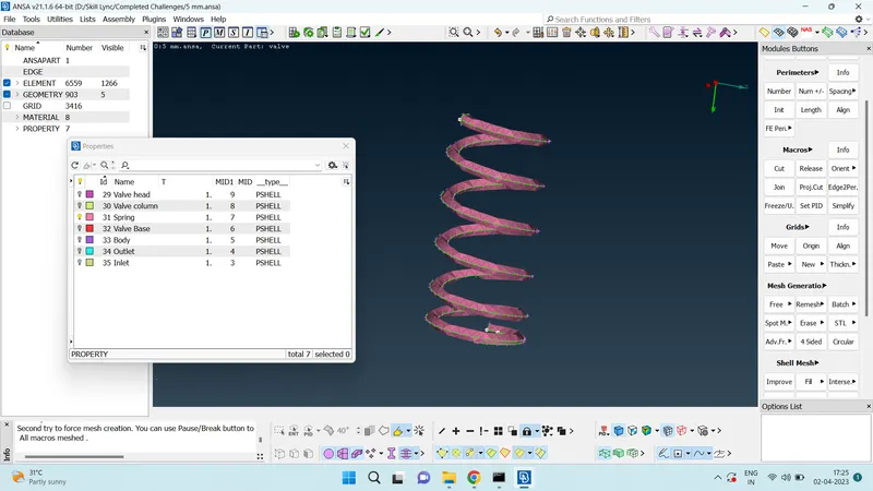
1 mm
The best quality for the surface among the three mesh length was achieved in 1 mm mesh length.
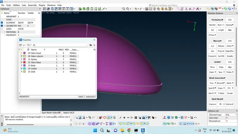
The spring also retained it's original shape when using 1 mm as the mesh length.
Outcomes
- Understood the use of various TOPO cleanup tools.
- How to use boolean opeartions efficiently to easily isolate parts and work on them.
- How to assign individual PID names to various parts of the geometry.
- Significance of mesh length.
- If the geometry size is small and mesh length is too big, it will result in poorly meshed geometry.
- It is always advisable to change the mesh length based on the size of the individual geometry parts.
- Very fine mesh in all part of the geometry will result in higher mesh elements and higher computational time. And Very large mesh will result in poor capturing of results while doing the analysis. So it better to adjust the mesh on each component of the geomerty based on the geometry size.