Week 4 Challenge : CFD Meshing for BMW car
Objective: Pre-processing of a BMW M6 using ANSA software.
Overview:
- Geometry Clean-up on Half Geometry.
- Topological Modifications where needed.
- PID Assignment.
- Prescribing Element Quality Criteria for each PID.
- Unstructured Surface Meshing (2d) using Triangular Elements PID wise.
- Eliminating Off-Elements.
- Getting complete meshed model using Symmetry tool.
- Setting up Wind-Tunnel.
- Surface Meshing of Wind Tunnel.
- Unstructured Volumetric Meshing using Tetrahedral Elements.
Procedure/Steps Involved:
STEP 1. Geometry Clean-up on Half Geometry.
1. Importing Model on ANSA.
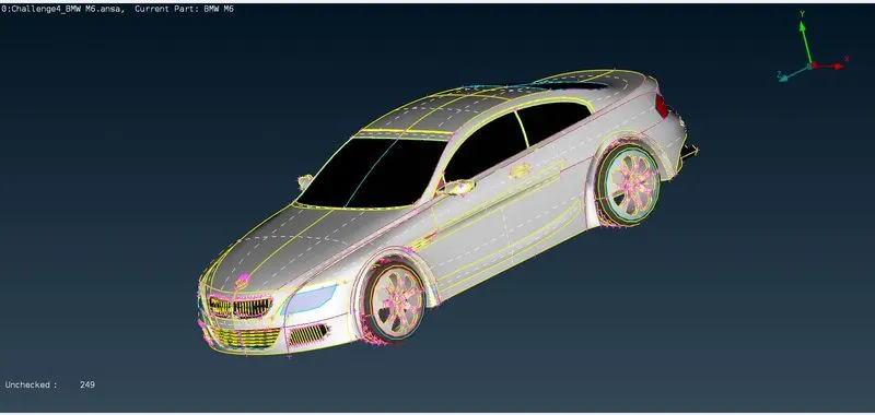
2. Improving Relolution of Coons By Setting up Length between Nodes to 1mm for Whole Model.
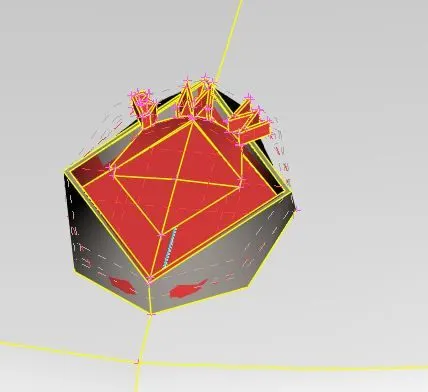
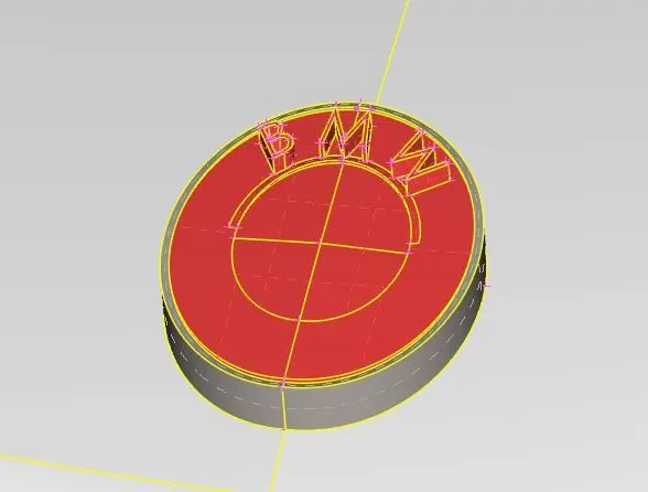
3. Deleting Half the model, other than Logo using Universal Delete.
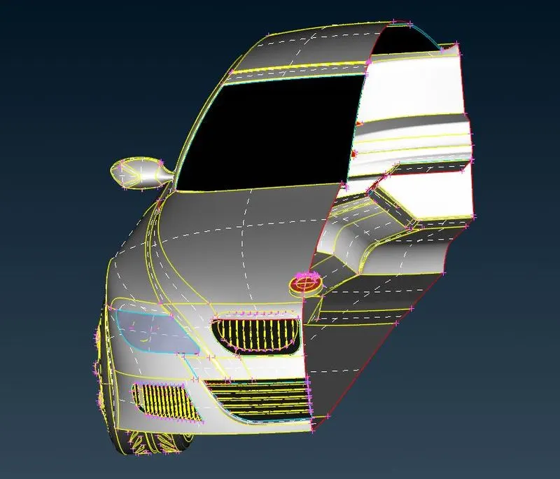
4. Checking Geometrical Errors.
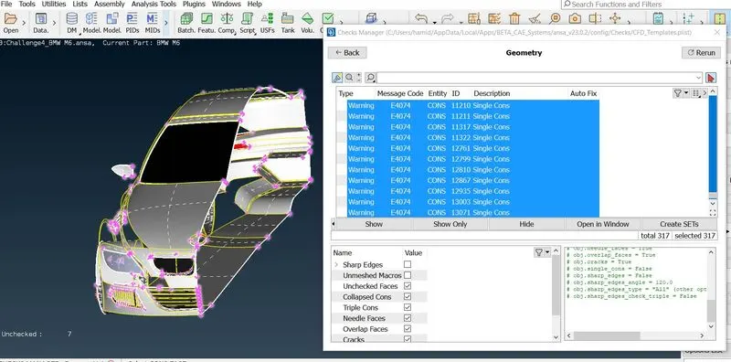
Step 2. Topological Modifications where needed.
1. Fixing Geometrical errors part by part using various Topological Modifications tools.
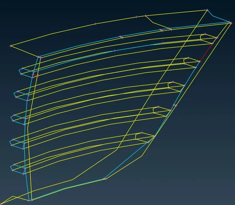
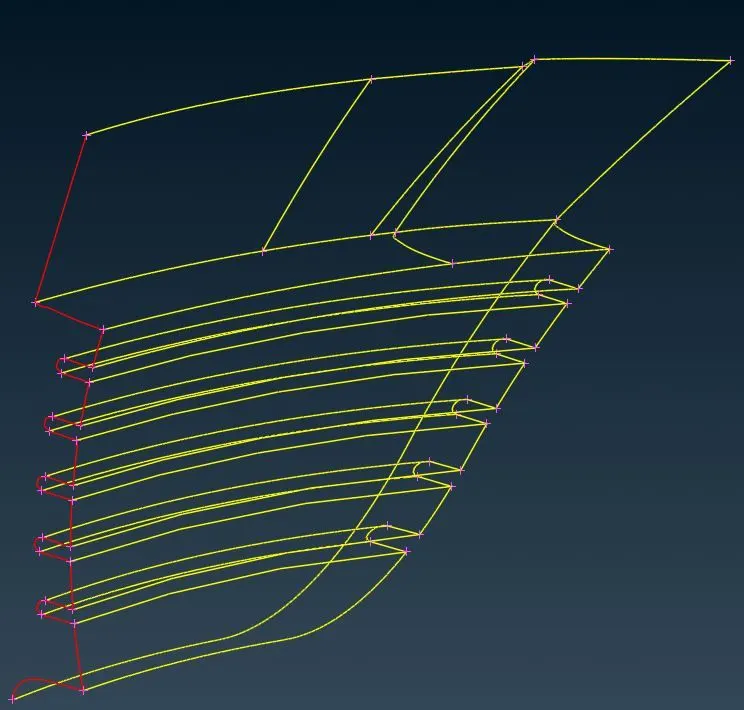
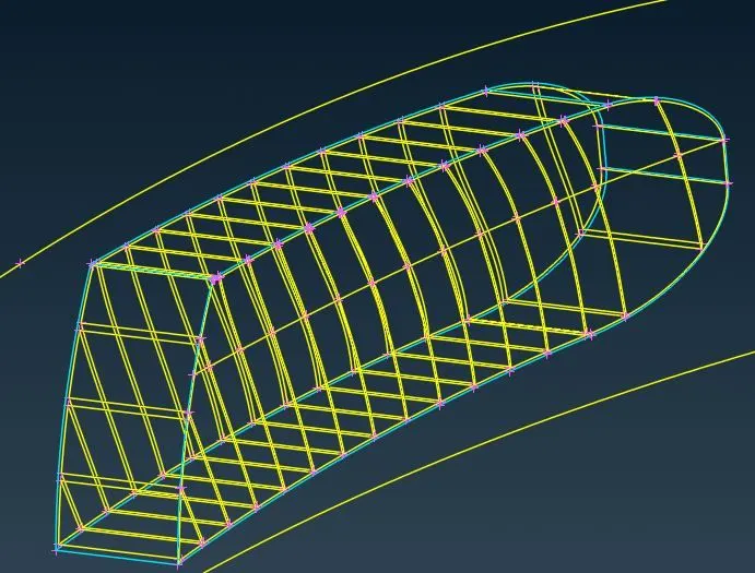
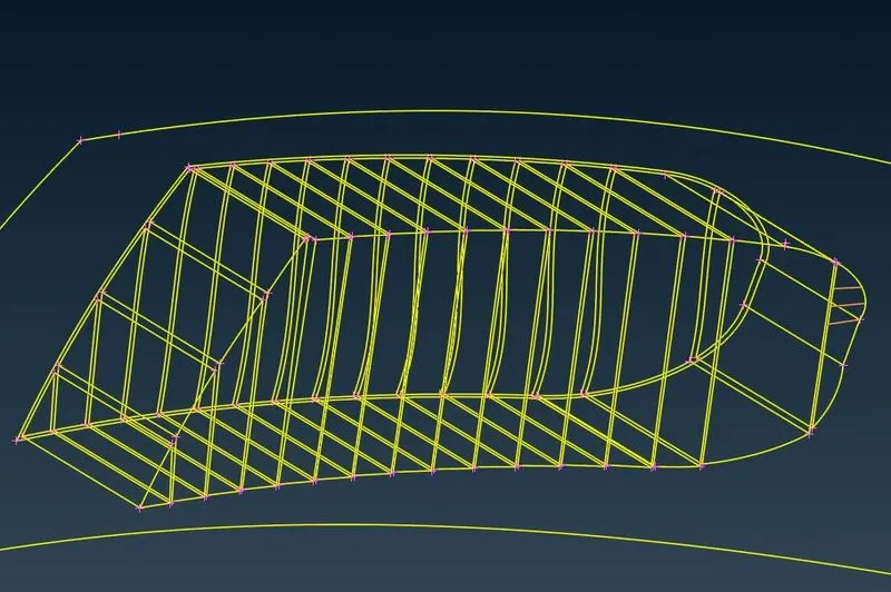
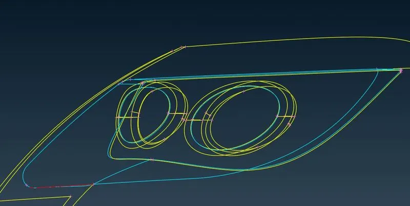
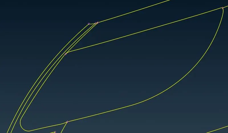
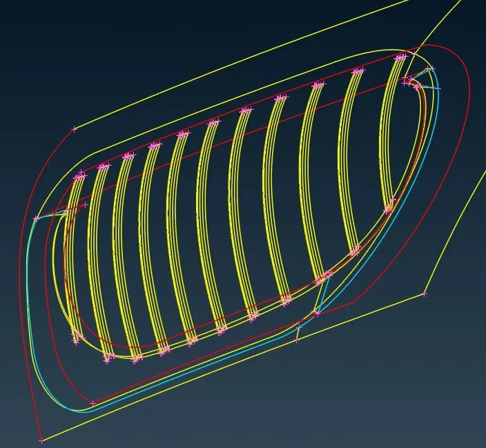
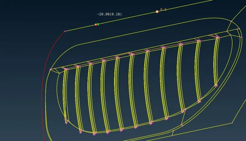
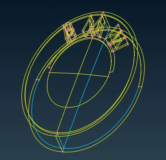
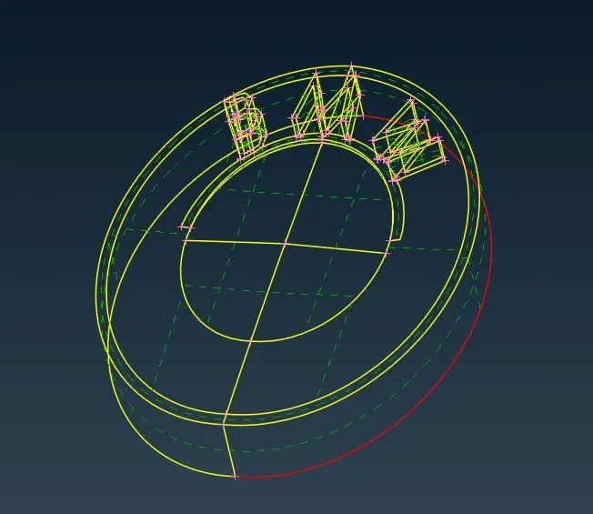
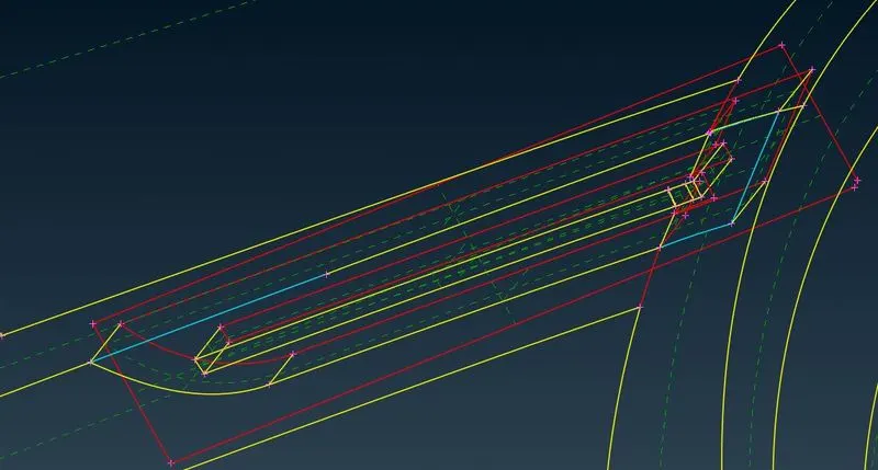
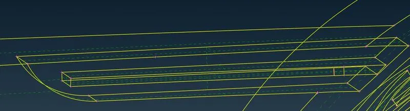
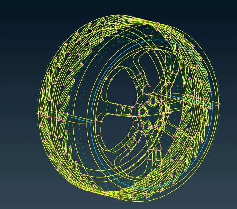
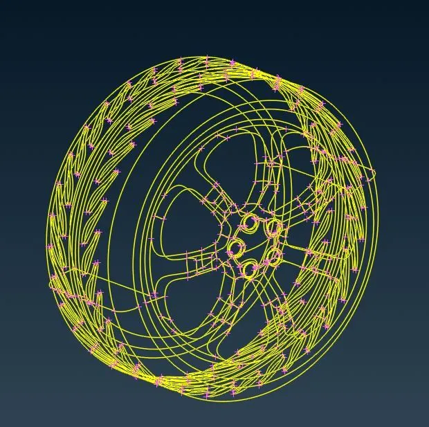
2. After fixing other such errors we apply Geometry Check to confirm TOPOLOGICAL CLEAN-UP.
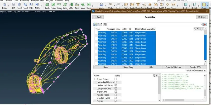
It can be seen, there are no errors other than the single coons present from half model.
STEP 3. PID Assignment.
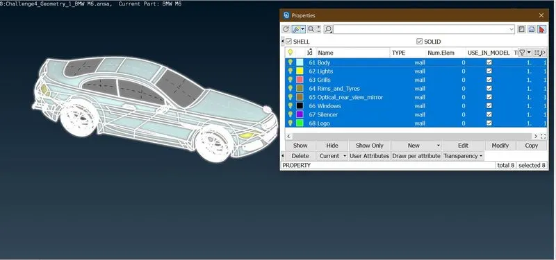
2. Now we assign the Target Length PID wise using the data below.
| PID | Target Length (mm) |
| Body | 3 |
| Lights | 4 |
| Grills | 1 |
| Rims and Tyres | 2 |
| Optical_rear_view_mirror | 2 |
| Windows | 2 |
| Silencer | 3 |
| Logo | 1 |
STEP 4. Prescribing Element Quality Criteria for each PID.
1. We also have some pre-set Quality critera which are as follows which are under OpenFOAM Deck.
| Quality Criteria |
Dimension (mm) |
Solver |
| Skewness | 0.5 | FLUENT |
| Min. Angle Quad | 45 | FLUENT |
| Max. Angle Quad | 0.7 | FLUENT |
| Min. Angle Tria | 30 | FLUENT |
| Max. Angle. Tria | 0.7 | FLUENT |
| Min. Length | As per PID | FLUENT |
| Max. Length | As per PID | FLUENT |
2. Now we investigate each PID to set-up minimum and Max length.
1. LOGO
Certain features have very fine dimensions.
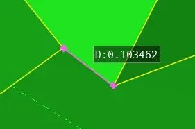
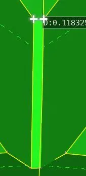
If we choosed min length as 0.1 mm than that will add unnecessary elements and will retard Computational Efficiency. Thus we must Consider modifying such features.
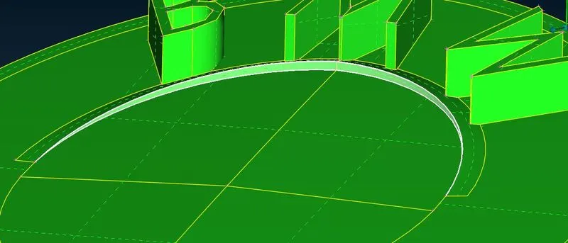
This is a needle face and will pose ERRORS during surface meshing. This also needs to be fixed.
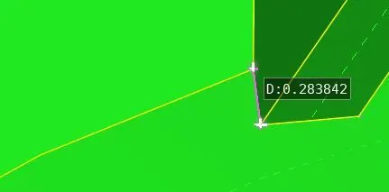
This is the minimum dimension on Logo its also a design feature, so we select Min. Length taking this as referance. For LOGO Min. Length = 0.2 mm. Max Length = 2 mm, from Tutorial.
2. Grills
Some of the silent dimensions are:
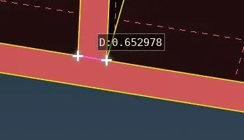
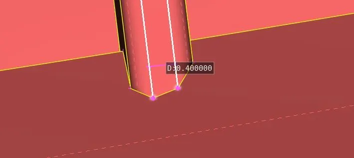
Grills has some of the most intricate features and these are essential for intake mainfold air intake. Thus on a safer side we can select Min. Length = 0.3 mm. Max. Length = 2 mm, from Tutorial.
3. Rims and Tyres
Near around Rims there are some fine features which might pose some restrictions on Quality Criteria.
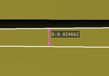
These features are overly refidined and thus we must modify them.
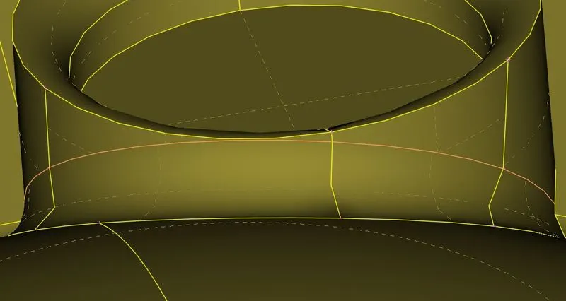
Adding additional coons to maintain curvature.
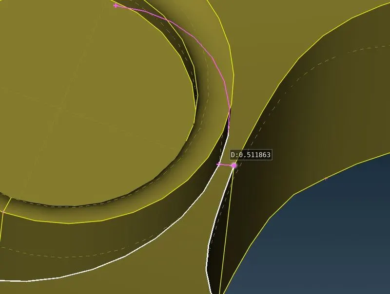
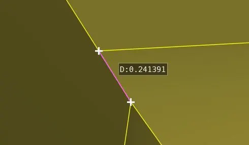
Finally this is the feature whcih upon removal will alter the Rim design significantly, so we specify the Minimum length on thi basis. Min. Length = 0.5 mm. Max. Length = 3 mm, from Tutorial.
4.Optical Rear View Mirror.
Again some features are overly defined and requires modification. These coons can be deleted without altering any design feature.
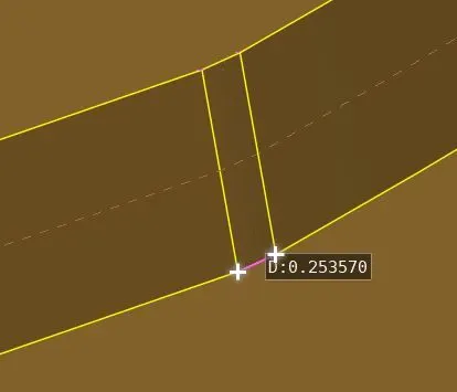
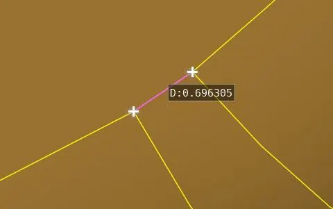
We specify minimum length as, Min. Length = 1 mm, and Max. Length = 3 mm.
5. Silencer.
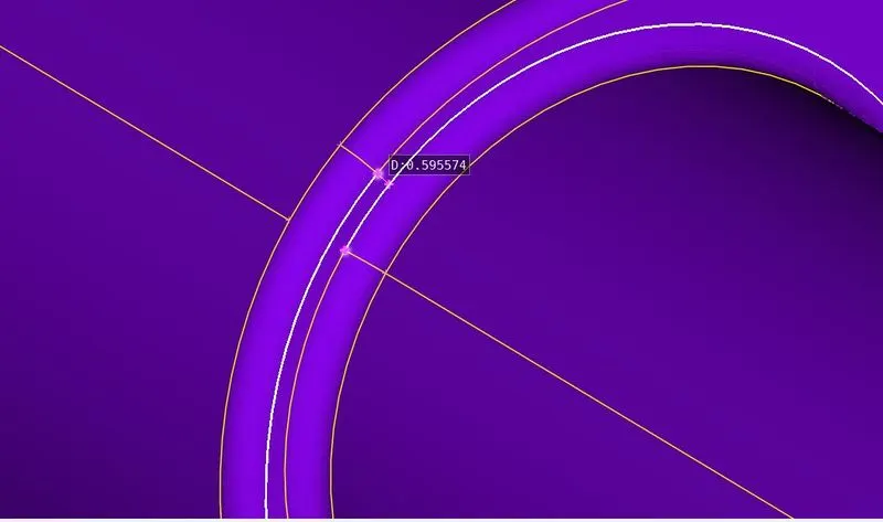
This feature can be modified such that the curvature is sustained, this can be done by adding coons and deleting the primary edge.
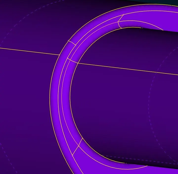
Thus we can specify min length as, Min. Length = 1 mm, Max. Length = 3 mm.
6. Lights.
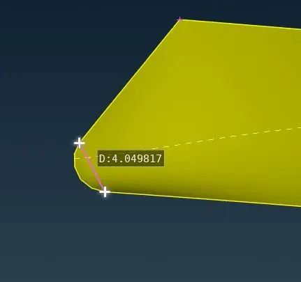
This part does not involve any intricate deature and can be specified easily.
Min. Length = 3 mm, Max. Length = 5 mm.
7. Windows
No intricate feature can be specified easily.
Min. Length = 1 mm, Max. Length = 3 mm.
8. Body
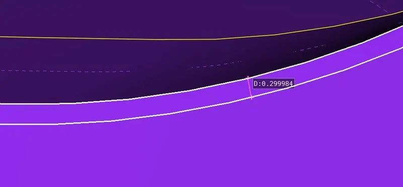
This Feature needs to be alterd, without deleting the Feature Coon.
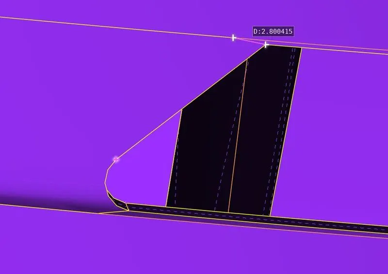
Body is a very critical part for meshing surface, as it is interconnected to every PiD, thus we specify parameters for it in such a way that least Elements will fail.
Min. Length = 1 mm, Max. Length = 5 mm.
Thus we can summarise as:
| PID | Target Length (mm) |
Min. Length (mm) |
Max. Length (mm) |
| Logo | 1 | 0.2 | 2 |
| Grills | 1 | 0.3 | 2 |
| Tires and Rims | 2 | 1 | 3 |
| Rear view mirror | 2 | 1 | 3 |
| Silencer | 3 | 1 | 5 |
| Windows | 2 | 1 | 3 |
| Lights | 4 | 3 | 5 |
| Body | 3 | 1 | 5 |
STEP 5. Unstructured Surface Meshing (2d) using Triangular Elements PID wise and eliminate the off-elements.
4. Now we imploy the surface mesh after specifying the Mesh Parameters and Quality Criteria for each PID.
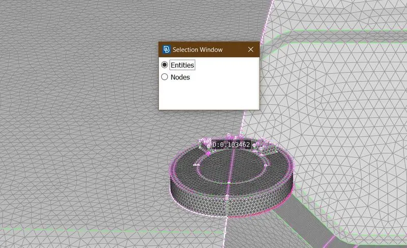
1. Logo
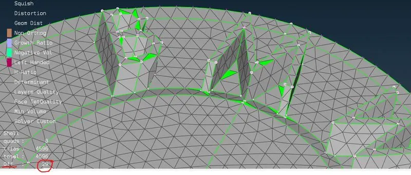
Off-Elements =29
Requires Reconstruction of surface mesh.
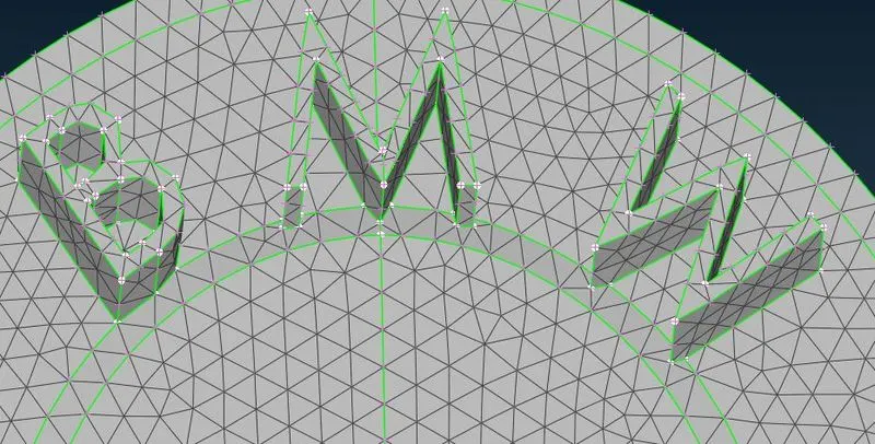
No off elements after reconsturction.
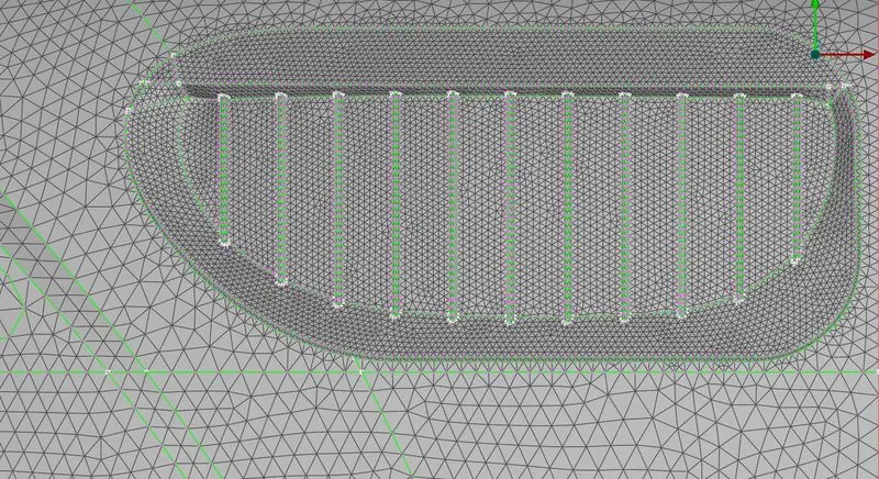
2. Grills
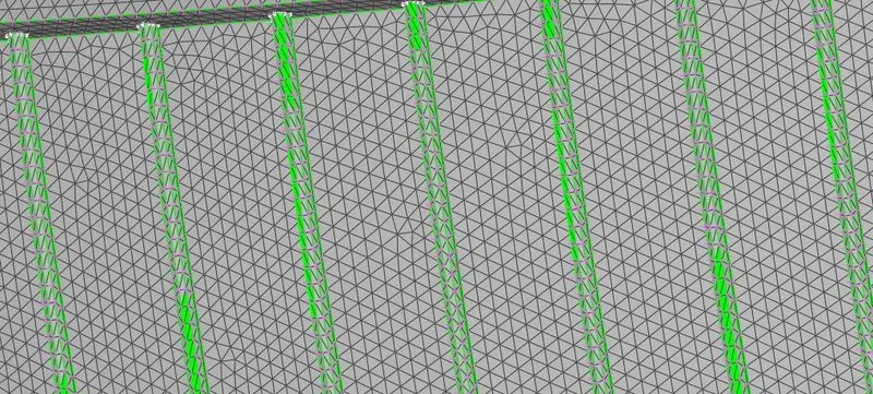
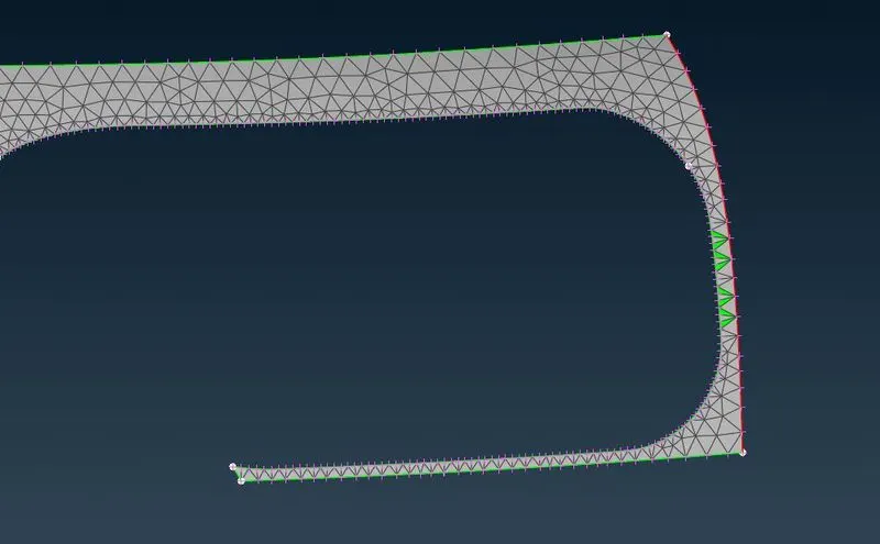
Most off- elements are failing for skewness and can be fixed after reconstruction.
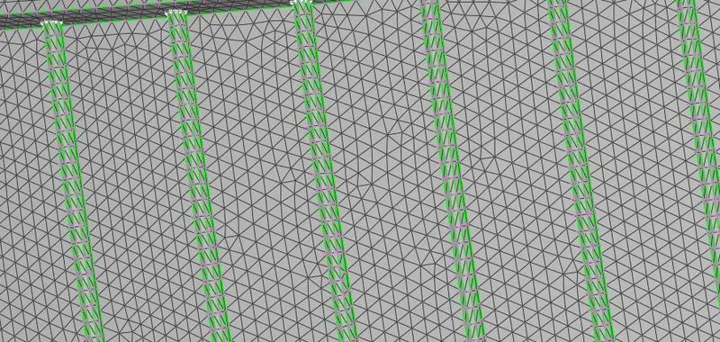
3. Lights
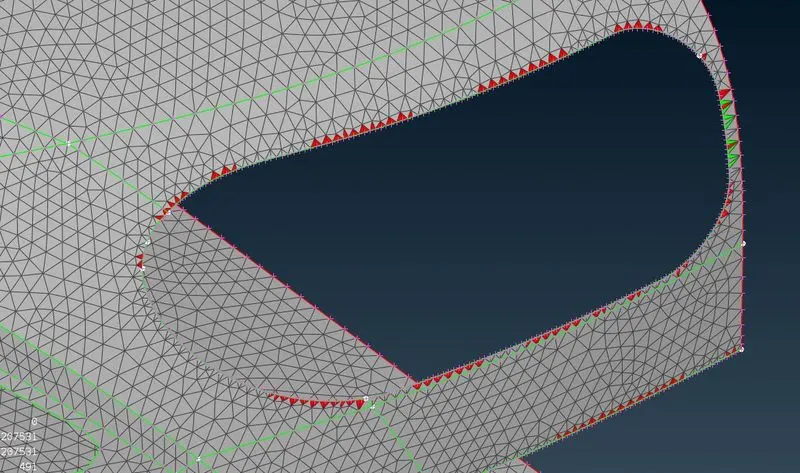
Some elements are failing for Max length.
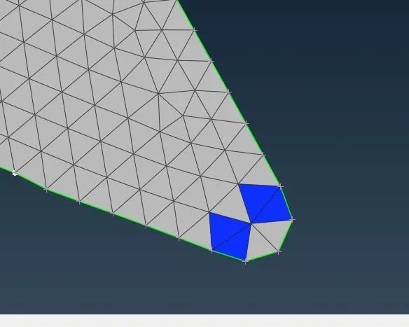
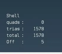
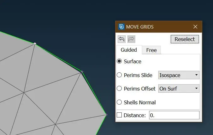
Even after Reconstruction there are off elements. Thus we fix these elements one by one using MOVE tool.
4. Silencer
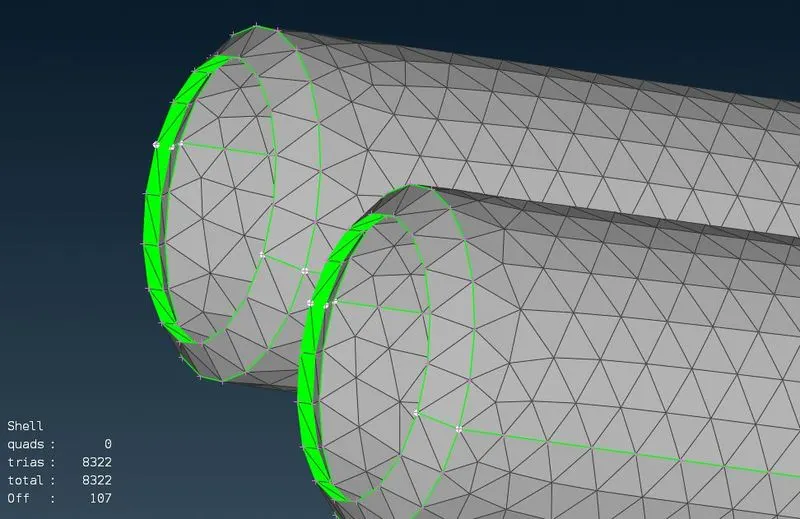
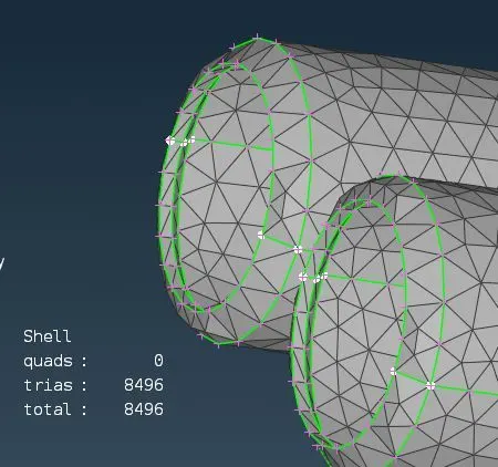
After reconstructing
5. Optical rear view mirror.
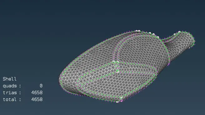
6. Rims and Tyres
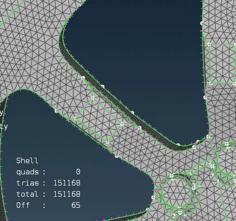
After reconstruction and other operations.
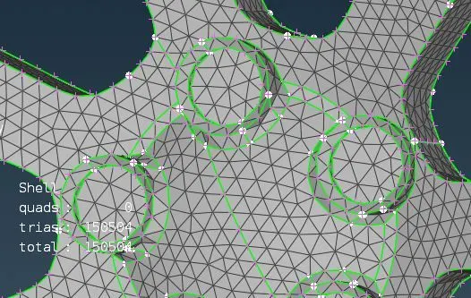
7. Windows
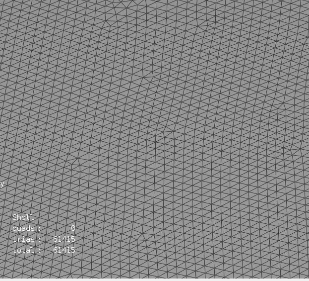
8. Body
As body is connected to every PID and thus we can not concretly specify Perimeter and Macros for it. We only specify Mesh parameters ans Quality criteria and imploy Spot Mesh.
After reconstruct
STEP 6. Getting complete meshed model using Symmetry tool.
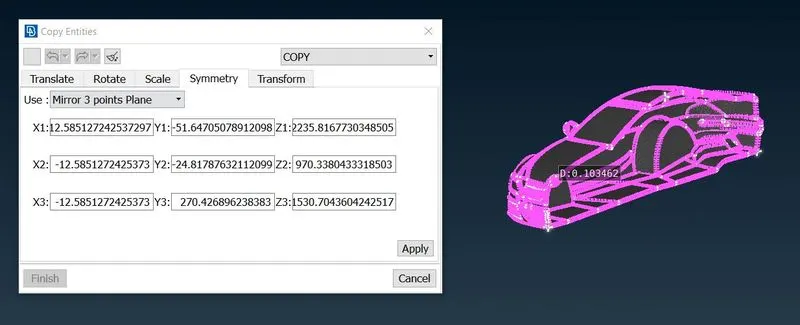
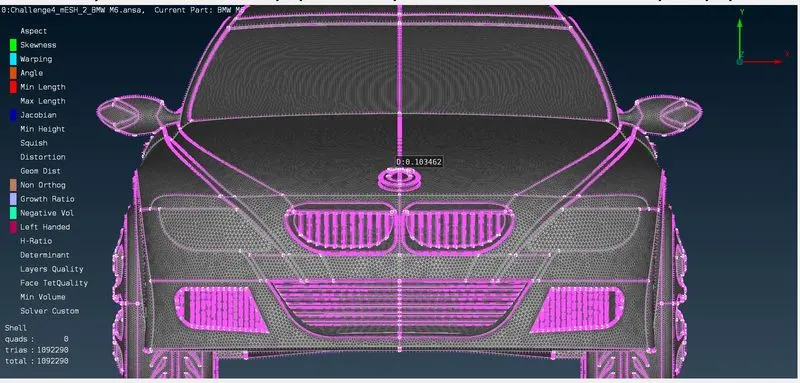
1. We select everything other than logo and perform symmetry.
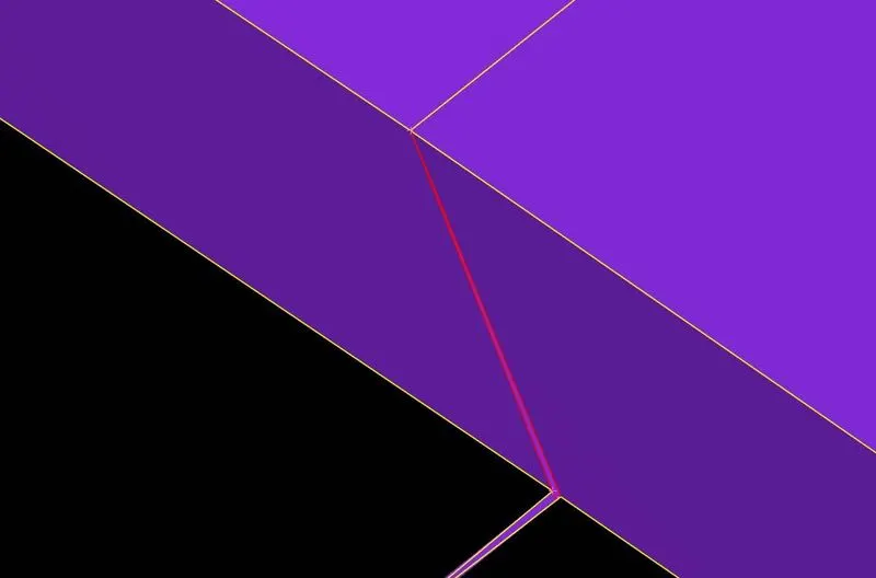
2. We resolve Single coons.
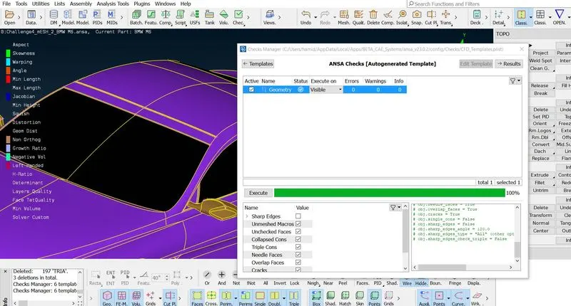
3. We run a final geometry check.This time we also check for unmeshed Macros.
SREP 7. Setting up The Wind-Tunnel.
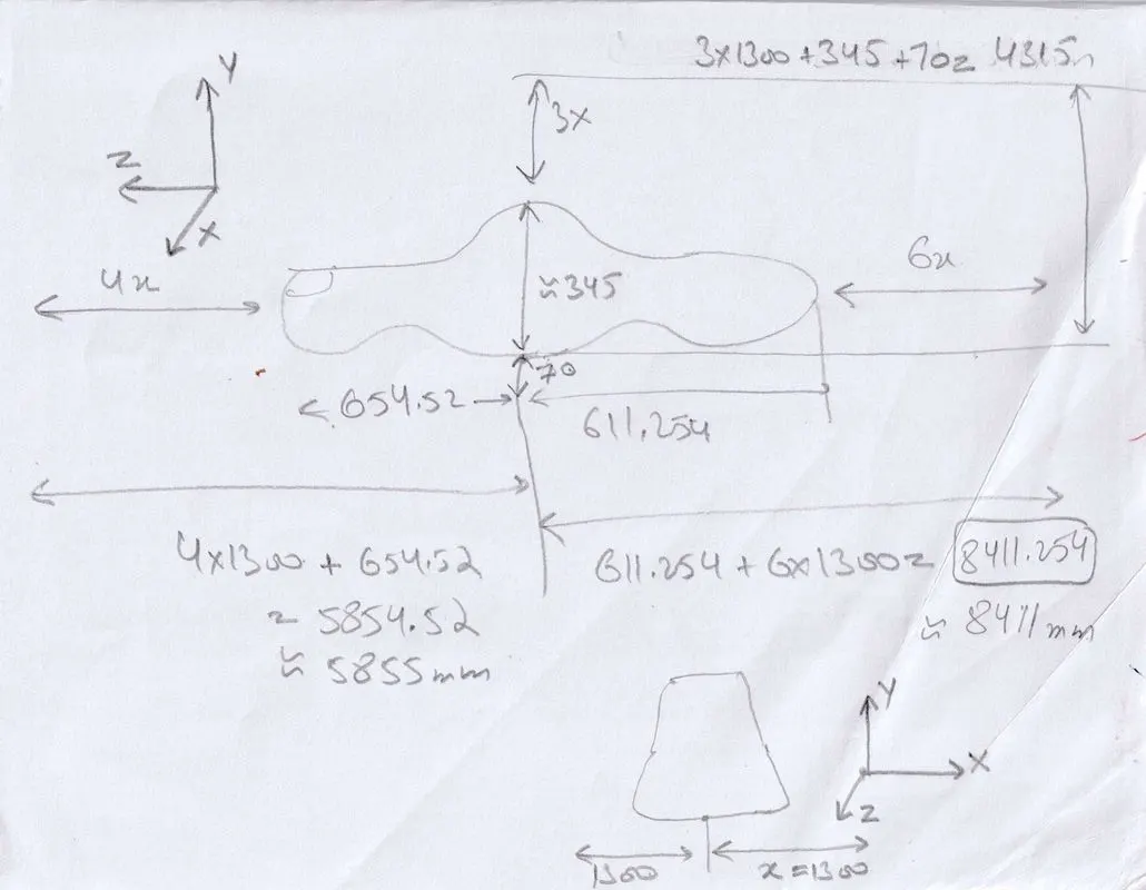
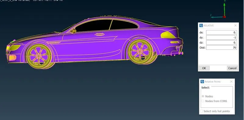
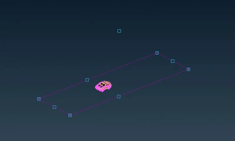
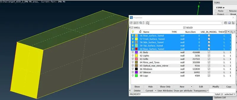
1. We use Points relative to specify required points, then we connect them to make curves using CREATE tool from CURVES.
2. Now we connect these curves to generate a surface. Then we use offset tool from faces to make a copy surface at top.
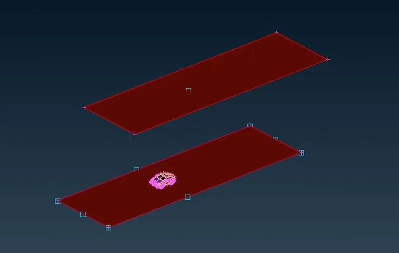
3. Now we connect the other faces and specify each to a PID.
STEP 8. Surface Meshing of Wind Tunnel.
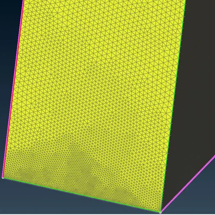
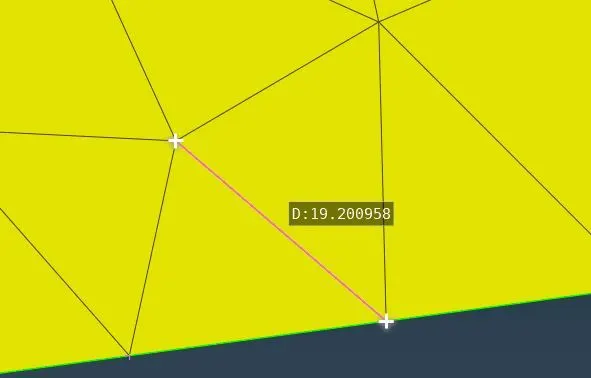
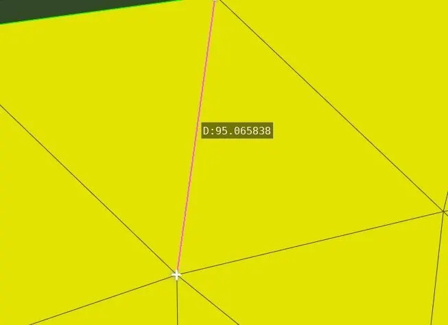
1. Now we set up the mesh parameters for top and bottom surfaces of Wind Tunnel. We will not prefix any such criteria to other surfaces as we need varying mesh there.
| Tunnel surface | Target Length mm | Min-Max mm |
| Top surface | 100 | 80-120 |
| Base Surface | 20 | 15-25 |
| Front surface | varying | varying |
| Rear Surface | varying | varying |
| Side surface | varying | varying |
2. Now we mesh top and base surface as per requirements.
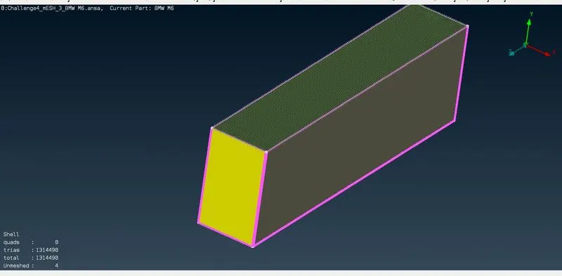
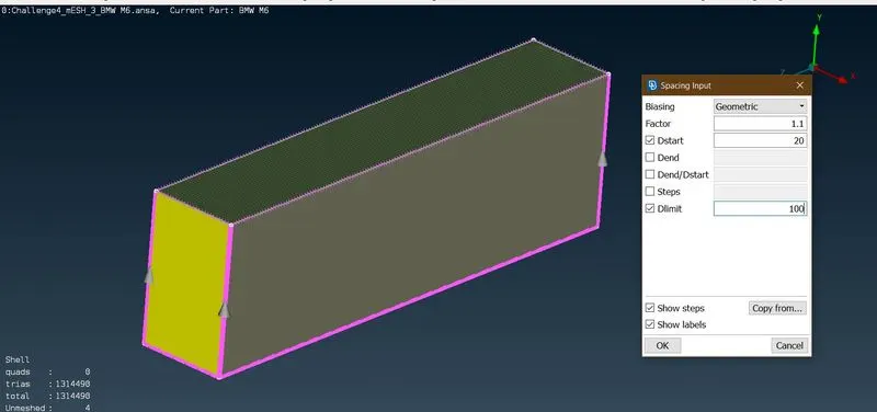
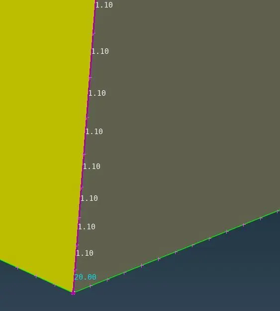
3. To generate varying mesh on other surfaces, we first de-select all mesh and quality criteria and the generate spacings geometrically on vertical edges as shown.
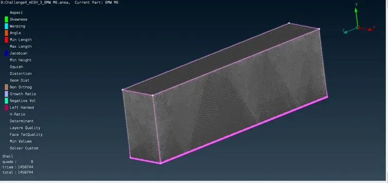
4. Now we reconstruct the wind tunnel surfaces to remove off elements.
STEP 9. Now we start Volumetric Meshing.
1. First we define the volumes using Define tool for the whole data base.
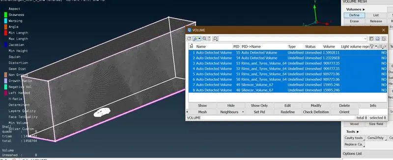
2. Now we delete the unnecessary volumes. and set up Volumetric mesh parameters. We select TETRA-CFD as 3D mesh Element.
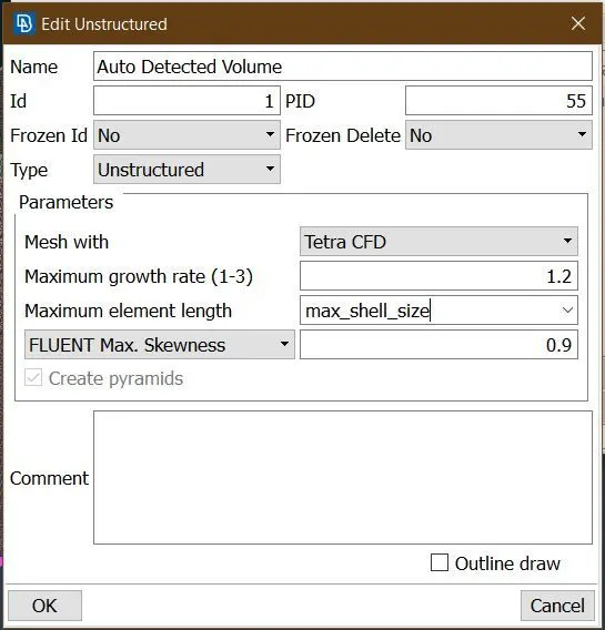
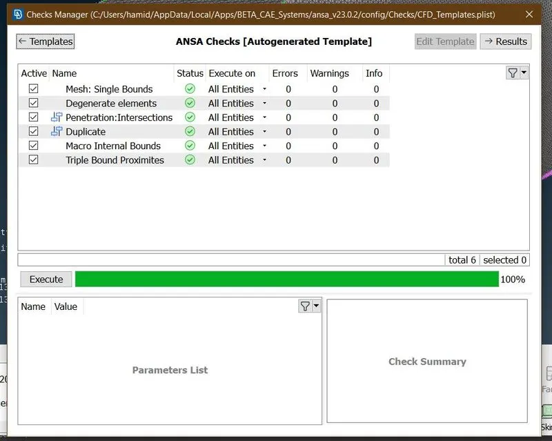
3. Now we run V-Mesh Diagonastics.
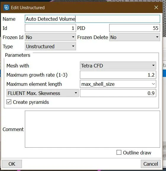
4. We set up V-Mesh by setting Unstructured, Tetrahedral Elements.
5. Finally Volumetric Mesh is Generated.
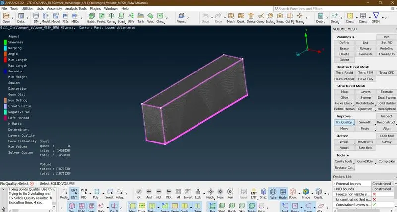
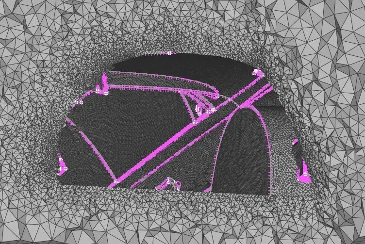
We can see the boundary region is finely varying in element size.
NOTE:- The size of V-mesh file even after compression was 175 MB and was unable to upload.
SUMMARY
| Element Type | Total Elements |
| Tria | 1458138 |
| Tetra | 11871030 |
Learning Outcomes.
1. Various tools avilable for Topologcal Clean-up: Extend, Intersect, Offset.
2. Addition of Points and Curves to complete Geometry.
3. Use of OpenFOAM Deck in setting up Element Quality Criteria.
4. Use of Mesh Refinement tools to eliminate Off-Elements: Reconstruct, Move, Split.
5. Use of Symmetry tool in ANSA.
6. Wind Tunnel Construction for Automotive Application.
7. Surface Meshing using Triangular Elements.
8. Volumetric Meshing using Tetragonal Elements.
Conclusion
Thie problem of Pre-processing a Model with specifics of an Automotive external surface, offers insight into the CFD pre-processing done in Automotive Industry. The model required a lot of work in eliminating geometrical errors and thus was helpful in practising various tools related to Error resolvement. An intuition was introduced, as to which volume needs to be deleted for External Aerodynamic Simulation. This assigenment is really helpful in preparing for further studies into Automtive Aerodynamic Analysis, where, after pre-processing following these steps, we can calculate critical parameters like Drag Force and Down force, essential for Aerodynamic performance assesment.