Week 3 Challenge : CFD meshing on Turbocharger
OBJECTIVE: Complete Pre-processing of a Turbo-Charger model using ANSA. Specification of components with required PIDs and mesing as per requirement.
Meshing Requirements:
| PIDs | Target Length (mm) |
| Compressor Casing | 5 |
| Turbo casing | 5 |
| Turbo Inlet Cover | 5 |
| Blade stage 1 | 1 |
| Blade stage 2 | 1 |
| Shaft Rotor | 1 |
| Impeller | 2 |
Procedure: We follow the following subsequent steps of Pre-processing:
- Topological modification of Geometry
- Assigning of PIDs
- Discretisation of Surface or Surface Meshing
- Discretisation of Volume or Volumetric Meshing
STEP 1: TOPO CLEANUP
1. We import the model on ANSA and inspect its surface errors. We can see a lot of overlaped surface and to confirm their locations we use TOPO on the whole model. This way, whereever the overlap occurs a Blue line is visible on edges whcih is called TRIPPLE COON.
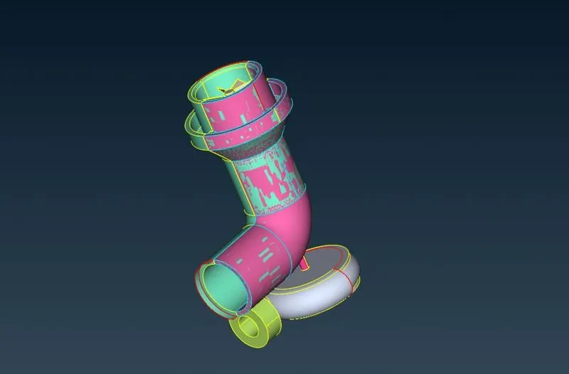
2. Now we delete the Pink cross-hatches which will delete the extra surfaces. We use the surface patching tools like Coons to add the missing surfaces. Then we check for Geometrical Errors. We also are required to make the whole of the rotor shat and both blade stages as a single volume. To do this we need to delete any surface that saperates these parts. This is essential for volumetric Mesh.
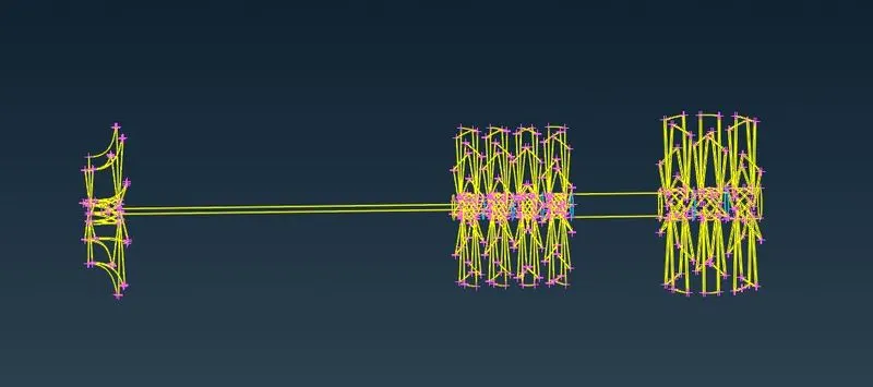
3. The Tripple coons are evident that there are saperations thet need to be deleted.
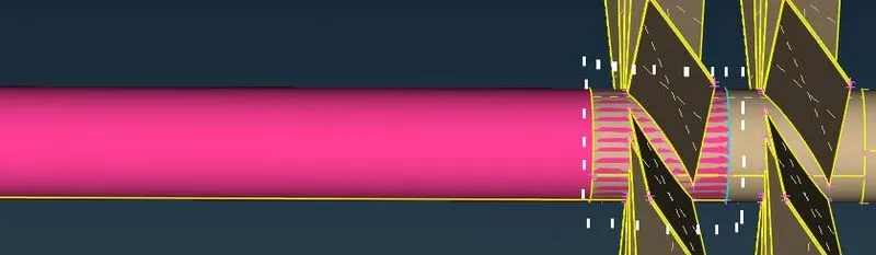
4. This overlaped surface if deleted will delete the rest of the shaft with it. We need to saperate this part, to do it we use PROJECT tool. After that we can use the FINE tool under AUXILARIES to fix the curvature.
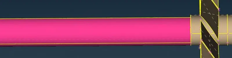
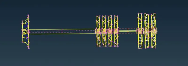
5. As there are no tripple coons present, thus we have obtained the whole shaft as a single volume.
6. Now we check for Geometrical Errors.
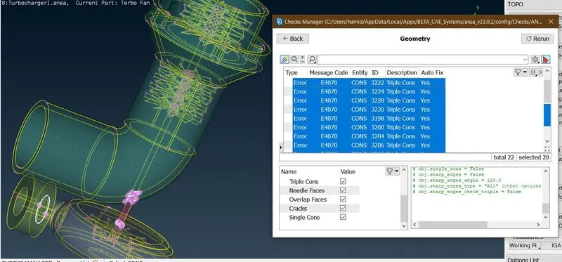
As we can see, there are only tripple coons which are essential for this case and should not be treated as an error.
STEP 2: PID ASSIGMMENT
We need to cover every open part for that we need to add extra surfaces, these extra surfaces will become part of their corresponding PIDs and will be assigmed with the Target length accordingly. The following are the new or extra PIDs
| PID | TARGET LENGTH (mm) |
| Turbo inlet | 5 |
| Turbo outlet | 5 |
| Compressor inlet | 5 |
| Compressor outlet | 5 |
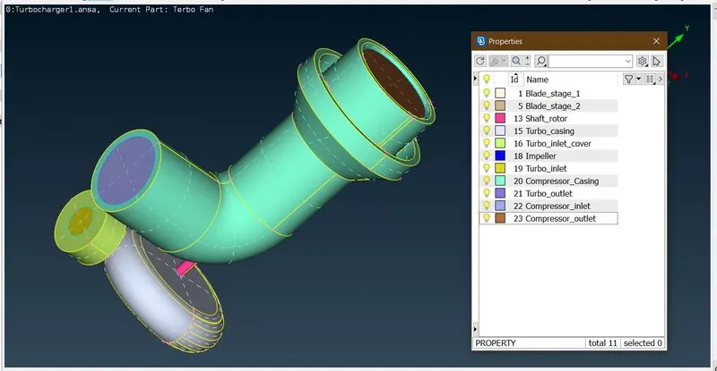
STEP 3: SURFACE MESHING
1. We first of all take all those components which are supposed to be assigned with Target length of 5 mm. These components are:
- Compressor casing
- compressor inlet
- Compressor outlet
- Turbo inlet
- Turbo outlet
- Turbo casing
For these PIDs we have the following specification for Surface meshing
Target length = 5 mm
Max length = 7 mm
Min Length = 3 mm
Element = Tria
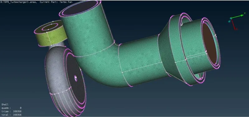
2. Now we select the PIDs which are required to be meshed with target length of 2 mm. The Pid is:
IMPELLER
Target length = 2 mm
Max length = 3 mm
Min Length = 1 mm
Element = Tria
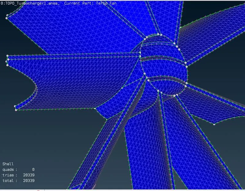
3. Now we go to the components where Target length is 2 mm. These components are:
- Blade stage 1
- Blade stage 2
- shaft rotor
Target length = 1 mm
Max length = 0.5 mm
Min Length = 2 mm
Element = Tria
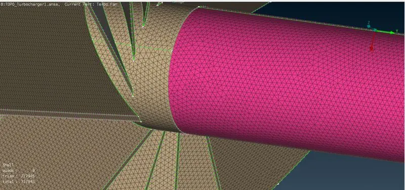
4. Now we look at the whole model.
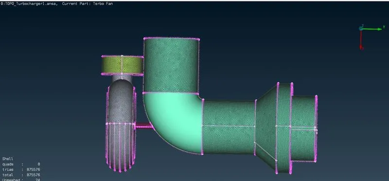
As we can see some surface have mesh disappeared. This is beacuse of a component with a different mesh setting in contact. To fix this and other such components we redo the meshing and we do not apply perimeter and length and keep it flesible.
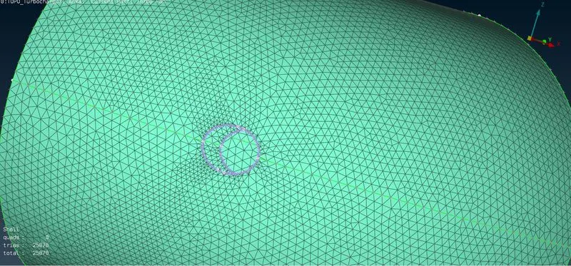
We can see the size of mesh elements are varying.
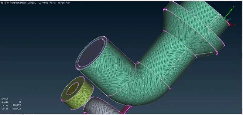
We can see the surface meshing of whole model is completed with following statistics.
TRIA ELEMENTS TOTAL = 918722.
STEP 4: VOLUMETRIC MESH
1. We check for the unmeshed volumes. To do that we click define and select auto detect and the following unmeshed volumes appear.
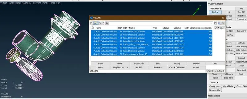
2. We select only those volumes where the fluid flows and delete the rest.
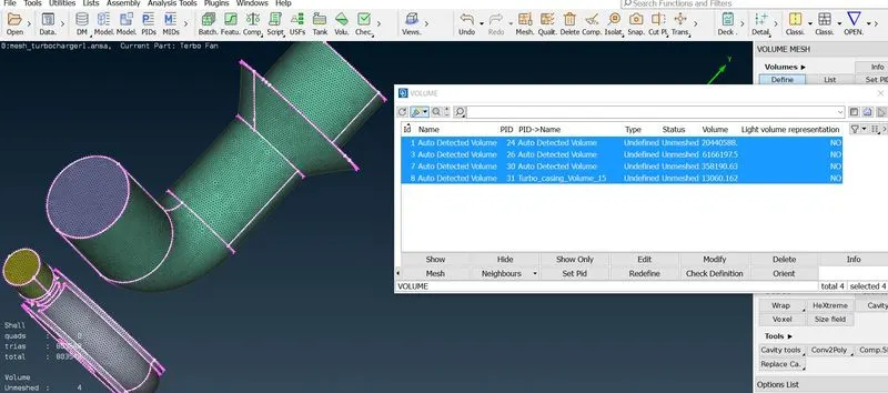
3. Now we assign the selected volumes with TETRA CFD MESH ELEMENT.
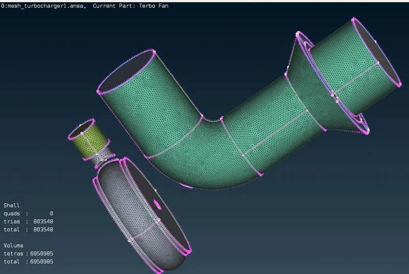
The total number of volume elements = 6950985
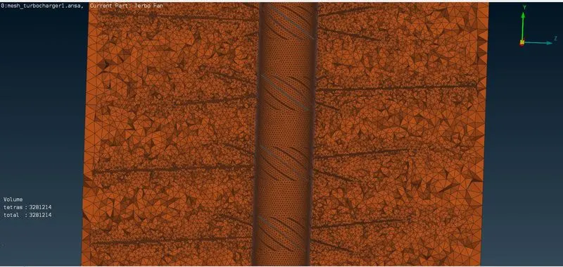
We can see the volume is properly meshed.
Learning Outcomes.
- Topological modification tools: PROJECT INTERSECT RELEASE TOPO.
- Requirements for volumetric meshing.
- Surface meshing as a pre-requisite for Volumetric meshing.
- Selection of particular volumes for volumetric mesh.
- TETRA CFD 3d element type.
- Implication of Target length on Volume Element.
CONCLUSION.
Overall we learned about the particularities of pre-processing a Turbocharger model. But this process also alllowed us to understand the working of Turbocharger by analysing its geometry.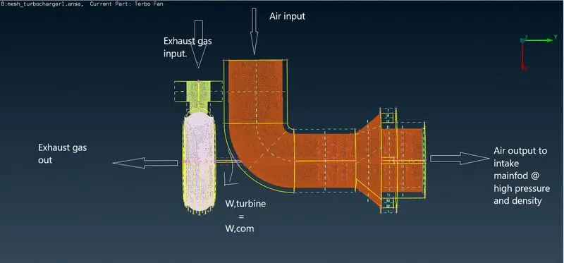
A turbocharger as shown, consistes of a radial flow turbine (Impeller) and an axial flow compressor (blade stages). Exhaust gas enters the turbine ( through turbo inlet cover) thereby rotating the impeller and escaping to atmospher through Turbo outlet. This way, impeller extracts the mechanical energy of Exhaust gases and supplies it to compressor through shaft. The compressor drags in the atmospheric air through compressor inlet and imparts work on it, thereby increasing its pressure energy. This causes increase in Pressure, Temperature and most importantly Density of air. This dense air is allowed to enter the intake mainfold of an Ic Engine and thus increases the volumetric efficiency of Engine. This improves the overall performance by making the charge leaner.