Week 4 Challenge : CFD Meshing for BMW car
AIM:TO DO CFD meshing on BMW car
OBJECTIVE: For the given model, check for the geometrical errors to make appropriate volumes. Create and assign PIDs as shown in the video. Perform surface mesh with the given target lengths as per PIDs.
- Body - 3 mm
- Lights - 4 mm
- Grills - 1 mm
- Rims and Tyres - 2 mm
- Optical Rear view mirror - 2 mm
- Window - 2 mm
- Silencer - 3 mm
- Logo - 1 mm
EXPLANATION:
SURFACE MESHING: The surface mesh is a representation of a surface that consists of vertices, edges and faces. There are currently two distinct alternatives for the surface representation in the deformable meshing literature, namely triangular and simplex meshes. Triangular meshes are composed of triangle faces which share each of their edges with exactly one other triangle face.
VOLUME MESHING: In 3D computer graphics and modeling, volumetric meshes are a polygonal representation of the interior volume of an object. Unlike polygon meshes, which represent only the surface as polygons, volumetric meshes also discretize the interior structure of the object. One application of volumetric meshes is in finite element analysis, which may use regular or irregular volumetric meshes to compute internal stresses and forces in an object throughout the entire volume of the object.
Process of any simulation: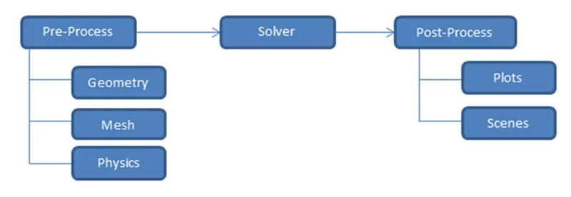
In this challenge we will be doing the pre-processing (Geometry and mesh only)of the given model in ANSA software.
PROCEDURE
- IMPORT THE GEOMETRY TO ANSA
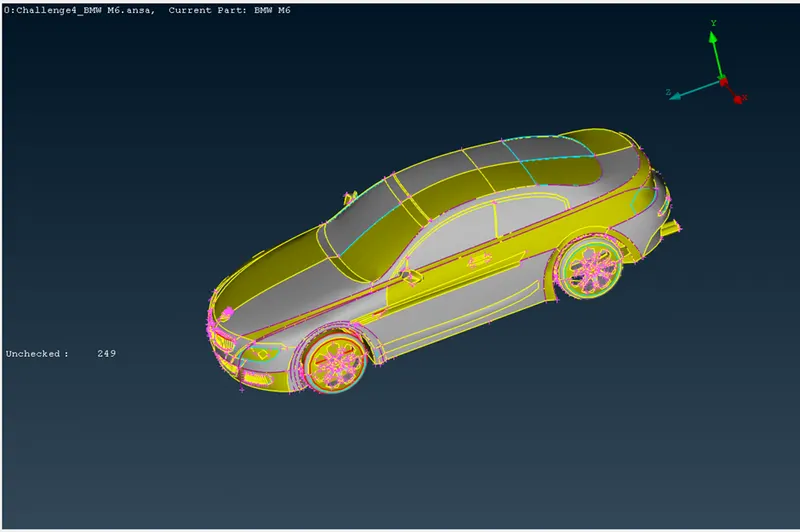
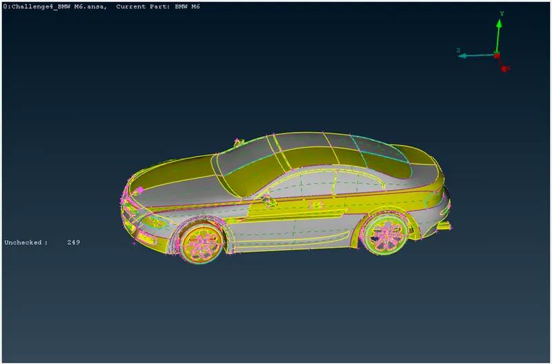
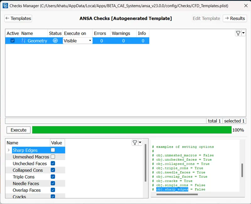
2. TO CHECK THE ERRORS IN THE MODEL
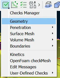
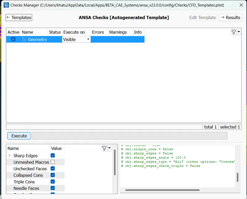
In ANSA, we can find out the errors present in geometry.This is done by using Checks command.In Checks command Geometry is selected.
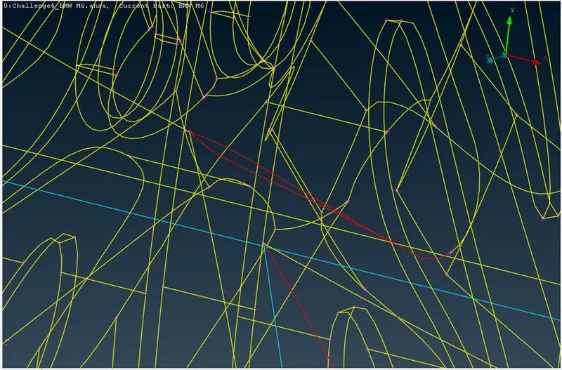
- We have to eliminate Single CONS. And TRIPLE CONS(where they are not required).
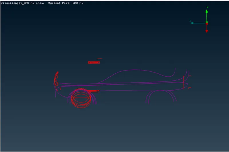
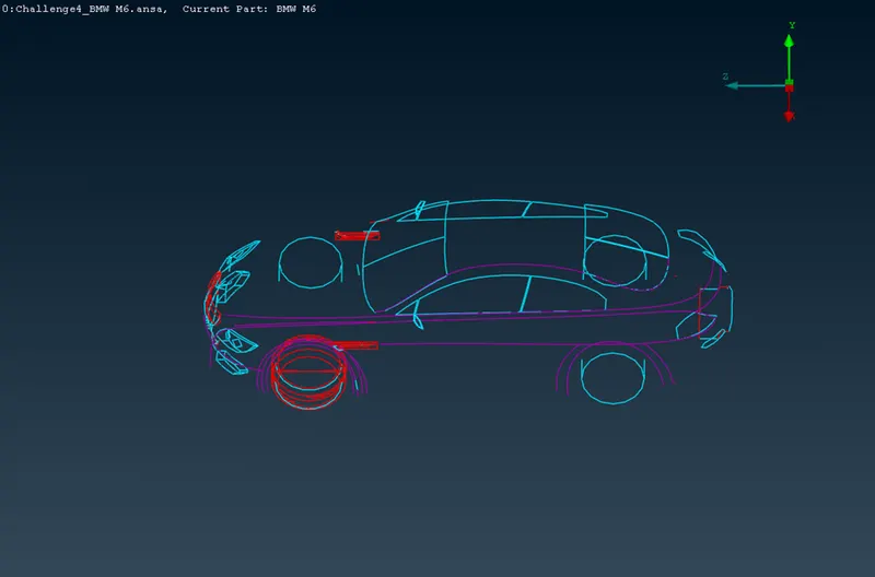
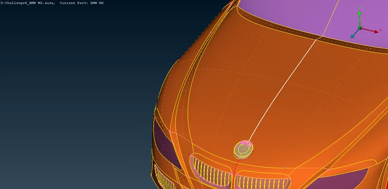
As it can be seen below that the given geometry is not smooth .
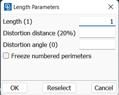
To make it smooth,we need to add hot points by using length command in mesh.mesh size is given as 1mm
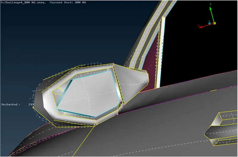
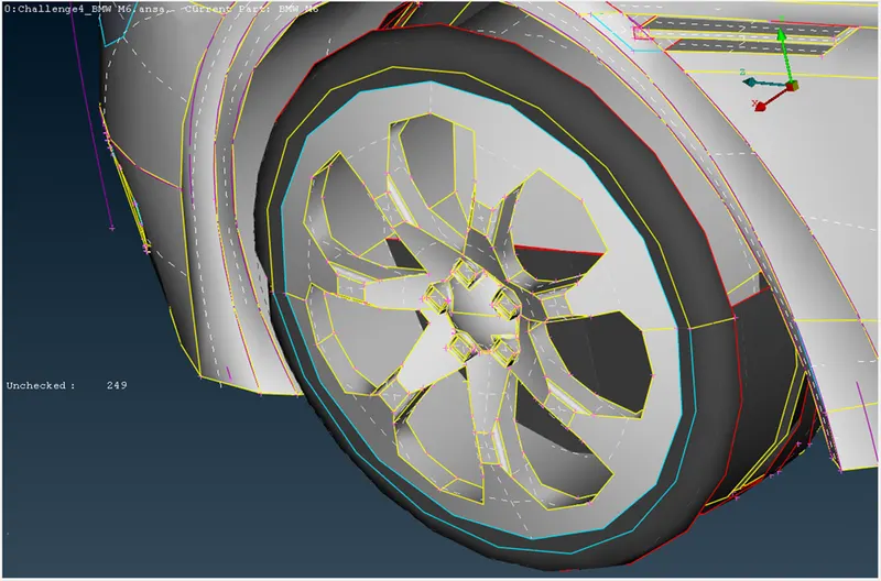
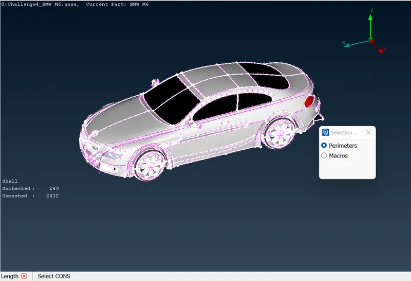
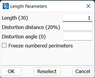
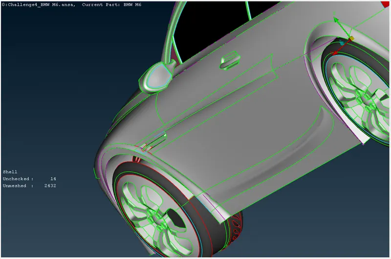
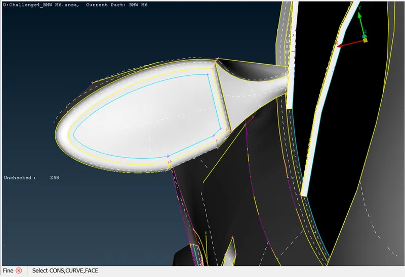
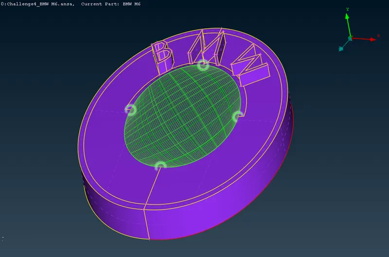
As the rhs of the given model is mirror image of lhs(except the logo).we can perform mesh on the any of the side and after the meshing is completed .We can copy the rhs/lhs w.r.t 3 points
- rhs of the model is deleted (except logo)
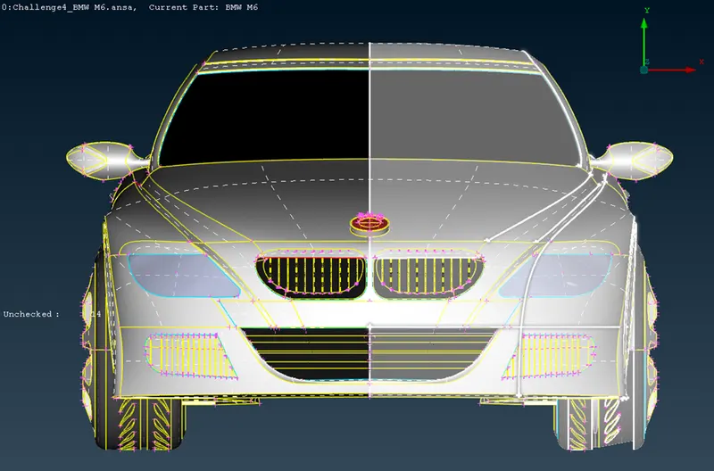
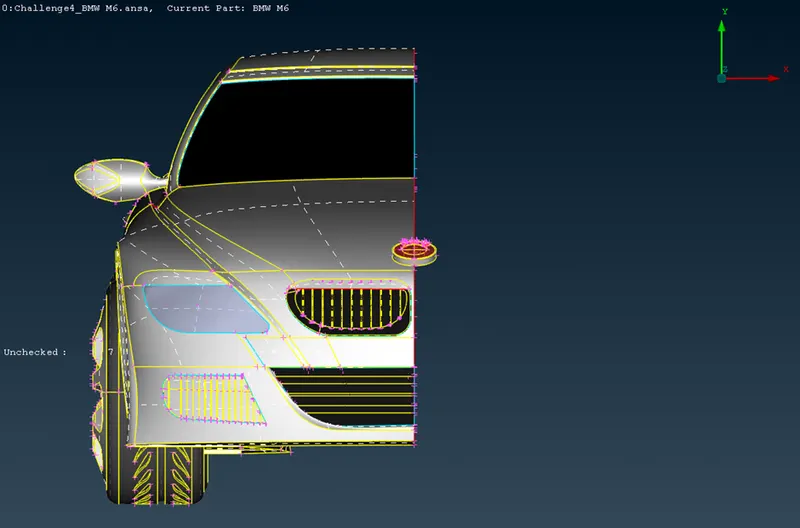
Single CONS and Triple Cons are eliminated using various commands(Paste,creating a new face,etc) in TOPO mode
FOR THE CFD SIMULATION OF THE CAR , WE WILL BE CREATING A FLUID DOMAIN.
In cfd simulation of car we have to deal with the external flow of air and car surface .So the surfaces inside the car is not taken into account while performing the simulation.
And thus, they will be deleted like the below surfaces
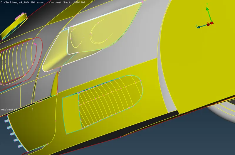
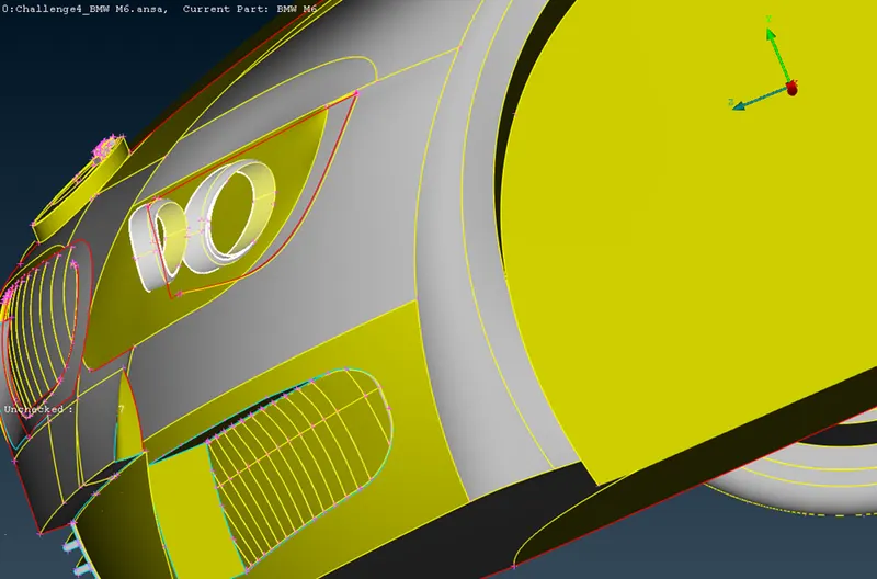
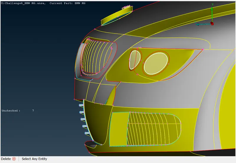
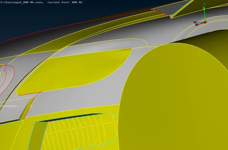
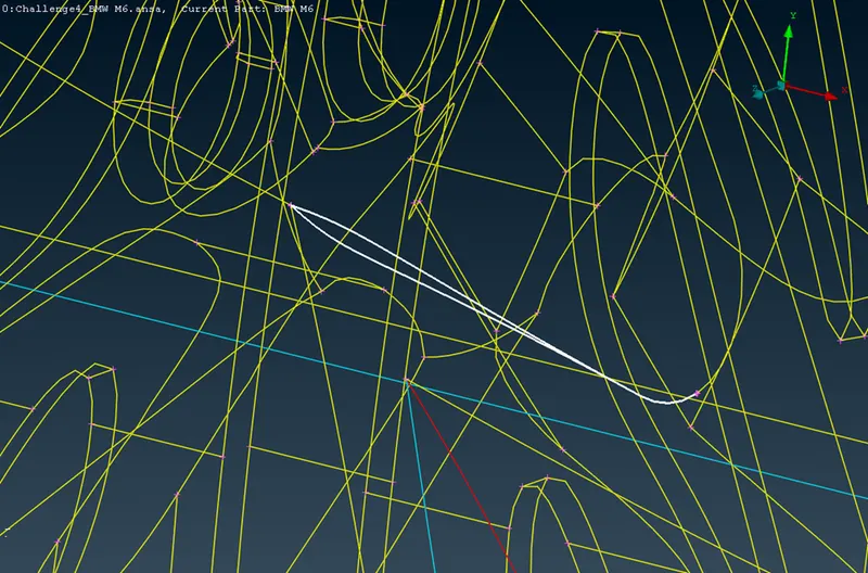
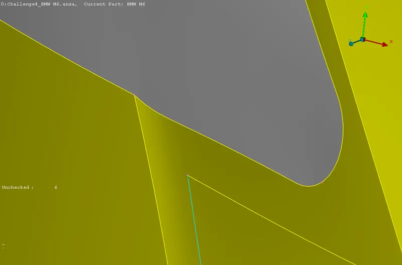
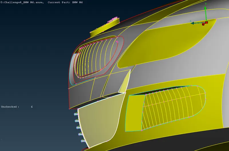
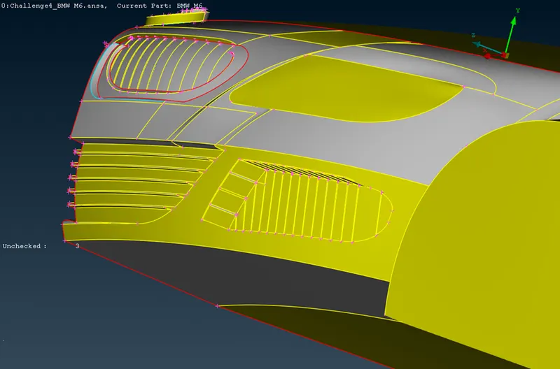
Following th same procedure for all the parts.
we get
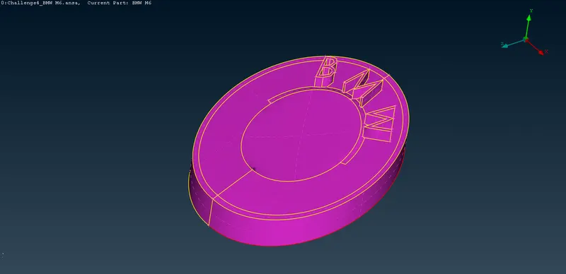
- LOGO
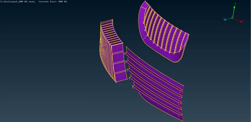
- GRILLS
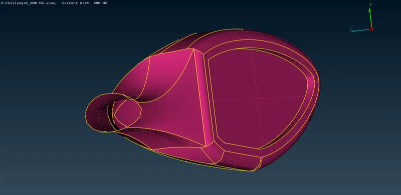
- OPTICAL REAR VIEW MIRROR
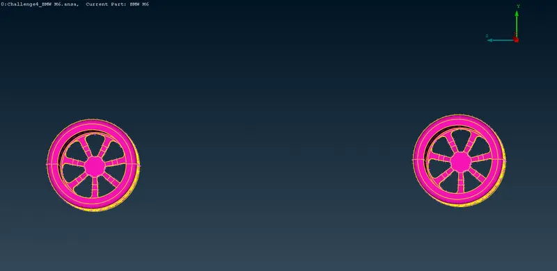
- RIMS AND TYRES
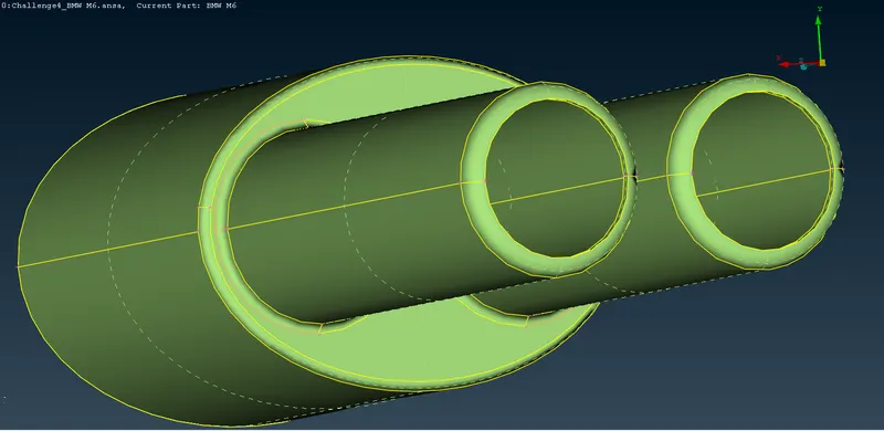
- SILENCER
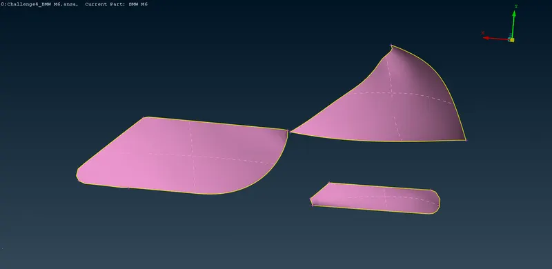
- LIGHTS
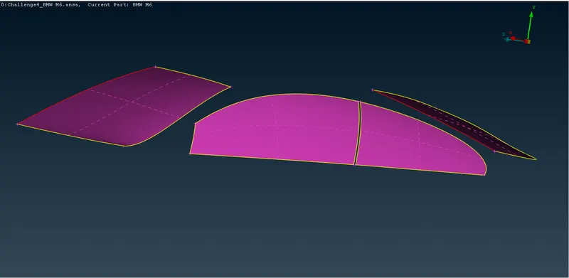
- WINDOWS
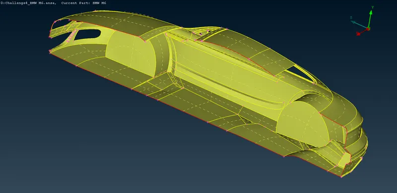
- BODY
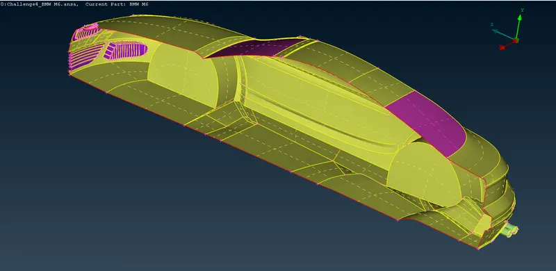
- TO DO NAME SELECTION
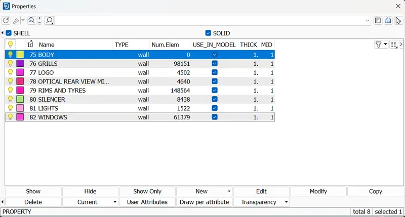
Now to do name selection,we can use ENT/PID/PID Region depending upon the type of selection
- Add properties (to assign boundary conditions)
- TO CHECK ERRORS IN THE GEOMETRY AFTER PERFORMING TOPOLOGICAL CLEAN-UP
As seen in below there are Single CONS present ONLY AT THE INTERSECTION OF RHS AND LHS WHICH WILL SOVED AT THE LATER STAGE in the geometry now.
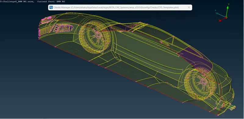
- BEFORE WE START MESHING EACH PID NEED TO BE ASSIGNED WITH A MINIMUM LENGTH AND MAXIMUM LENGTH
- MINIMUM LENGTH IS DECIDED ON THE BASIS OF MINIMUM DISTANCE BETWEEN TWO NODES IN A PID
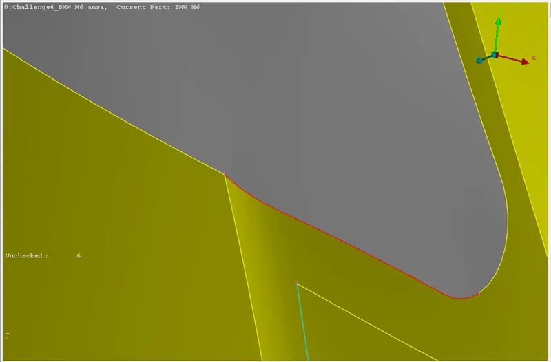
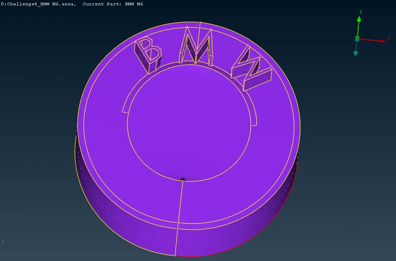
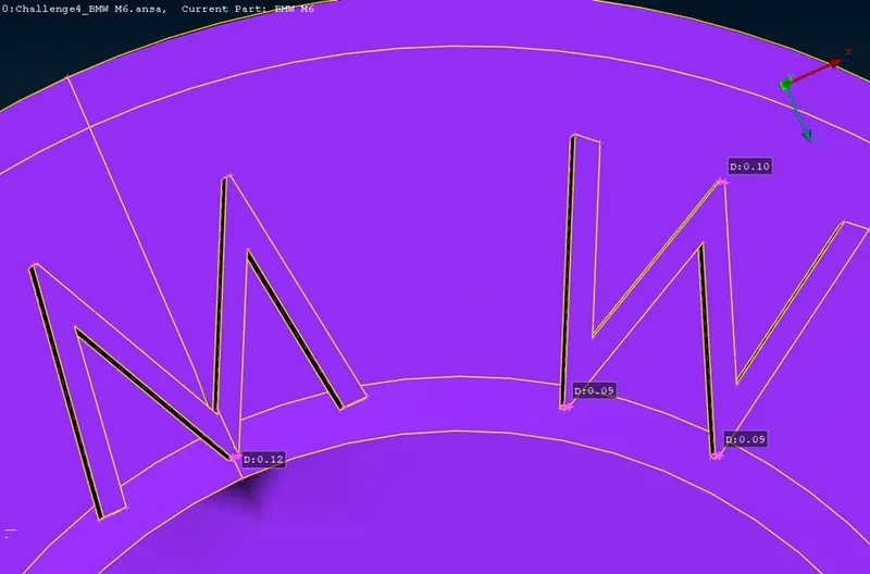
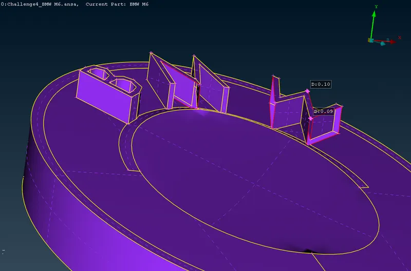
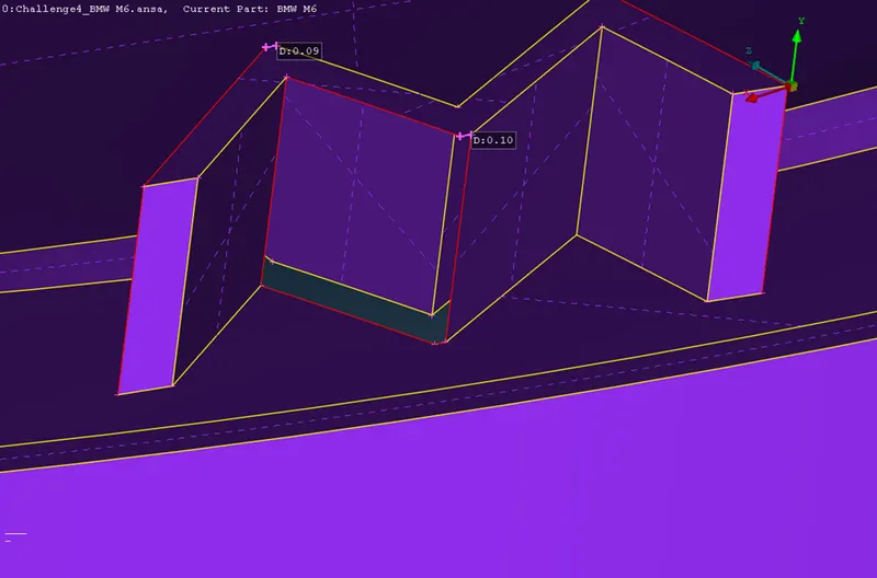
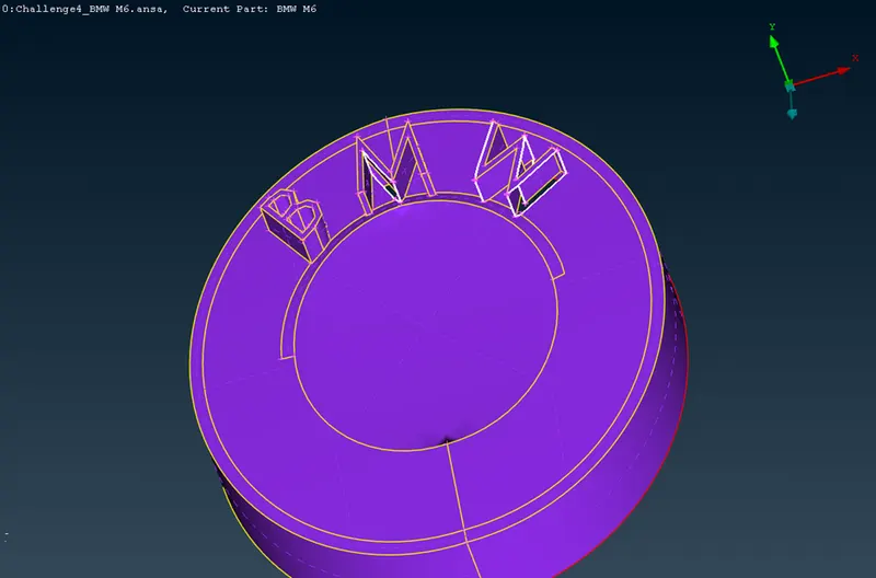
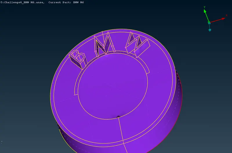
but if a entity is not necessary then it is deleted and a new entity is created.
like the one below
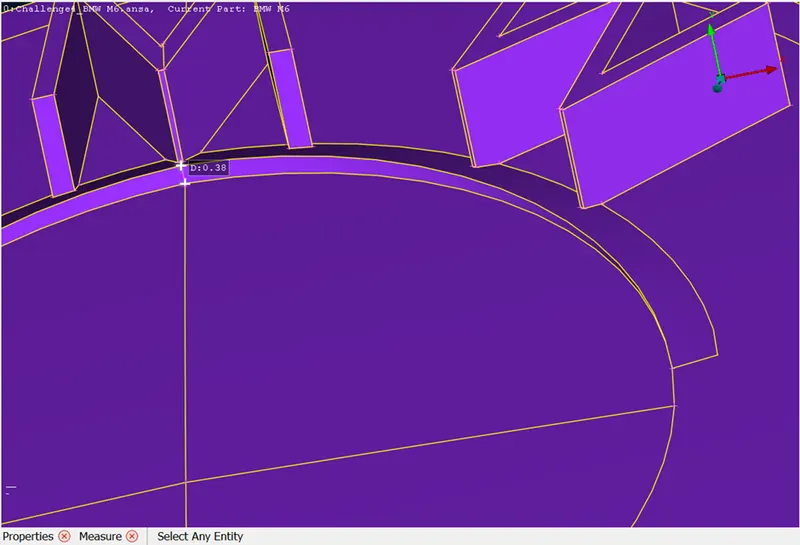
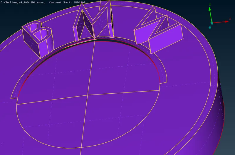
MESHING
We have to create a mesh
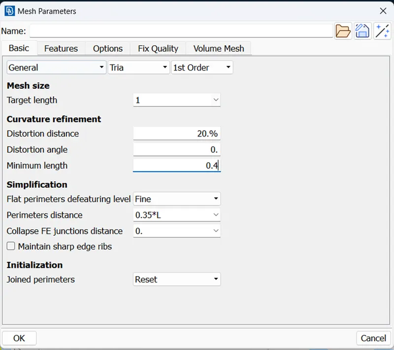
- for this select Classic Mesh in Mesh Module.
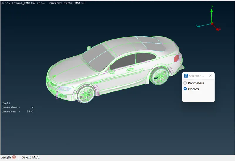
- prop window will appear having Perimeters and Macros
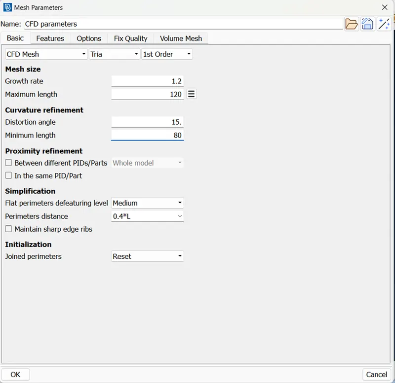
- for the options we have to box select the geometry and give length as stated in the problem statement
- Perimeters-green portion
- Macros-enclosed in perimeter
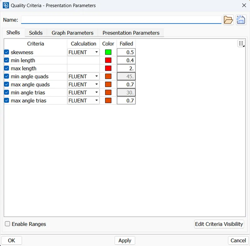
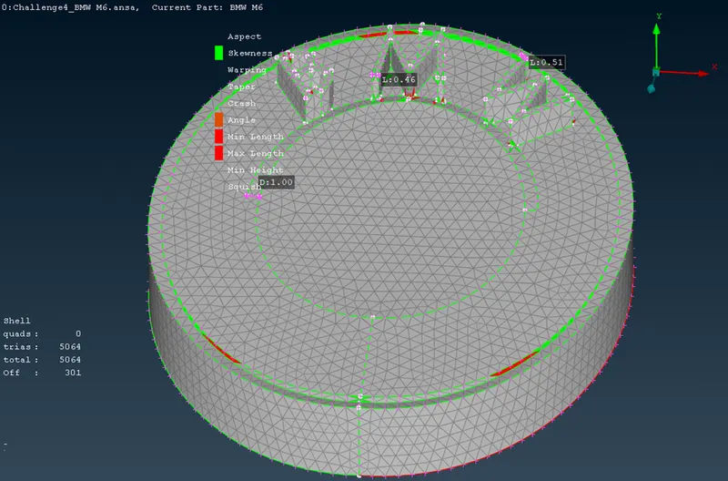
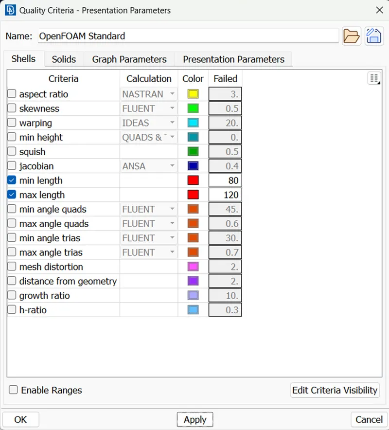
TO FULFIL THE QUALITY CRITERIA , WE NEED TO ELIMINATE THE OFF-ELEMENTS IN THE PID.
This can be done by
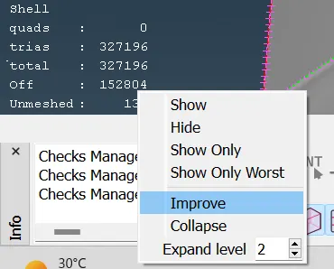
- by using IMPROVE command
- by using MOVE command IN GRID
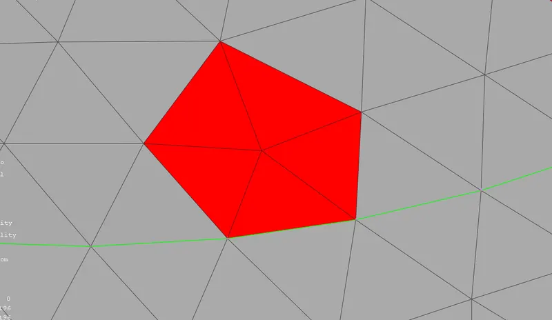
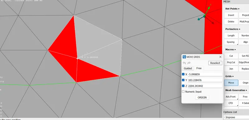
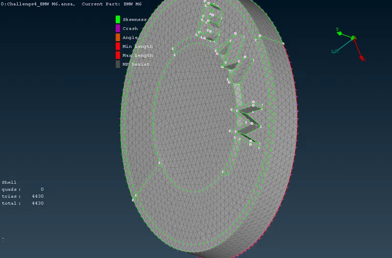
thus we can perform the meshing of all PIDS in same manner
after meshing all PIDS (except BODY),WE need to FREEZE the MESHING
THIS IS DONE AS THE BODY IS IN CONTACT WITH OTHER PIDS,MESHING has been performed on these PIDS.the minimum length of these PIDS cannot be changed.
Therefore at the intersection of BODY and other PIDS , there needs to be a transition in the mesh length of BODY.
MINIMUM LENGTH of BODY CAN BE THE LEAST OF MINIMUM LENGTH OF ALL OTHER PIDS
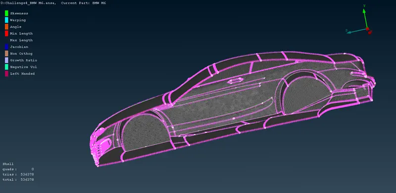
| SR.NO | PID | MINIMUM LENGTH(mm) | MAXIMUM LENGTH(mm) |
| 1 | LOGO | 0.4 | 2 |
| 2 | GRILLS | 0.3 | 2 |
| 3 | LIGHTS | 3 | 5 |
| 4 | OPTICAL REAR VIEW MIRROR | 0.5 | 4 |
| 5 | RIMS AND TYRES | 0.5 | 4 |
| 6 | SILENCER | 1 | 5 |
| 7 | WINDOWS | 0.5 | 4 |
| 8 | BODY | 0.4 | 5 |
now we need to copy all PIDS(EXCPECT LOGO)
BELOW ARE THE STEPS TO MIRROR THE LHS
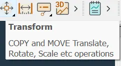
- First select copy from
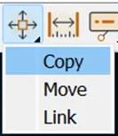
- THEN SELECT ALL ENTITIES EXCEPT LOGO
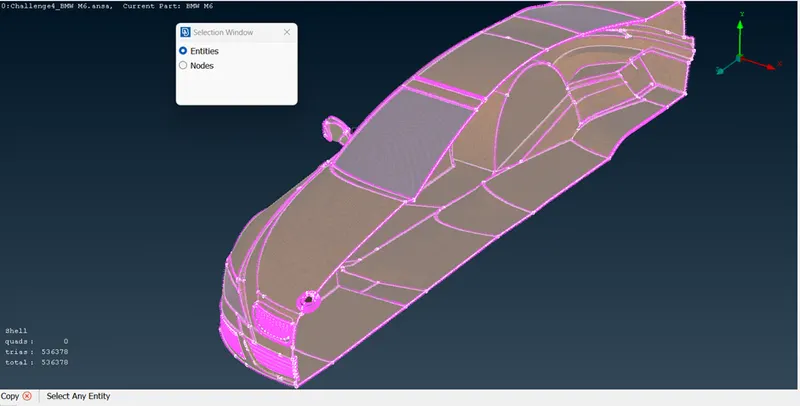
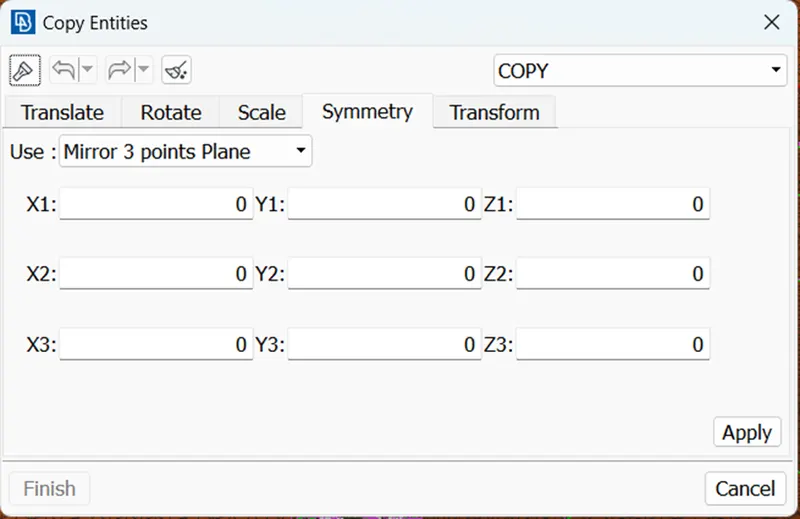
- USE MIRROR 3 POINTS PLANE IN SYMMETRY
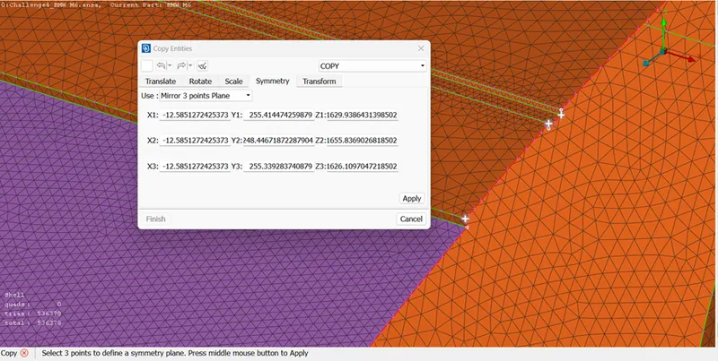
- SELECT THREE POINTS
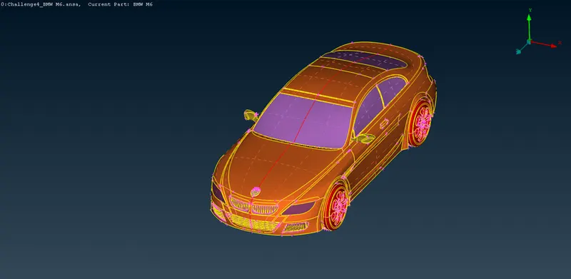
TO ELIMINATE THE SINGLE CONS USE PASTE COMMAND
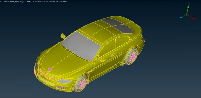
CHECK FOR ANY ERRORS IN THE GEOMETRY
CFD IS PERFORMED ON THE CAR,IN WHICH FLUID(AIR)IS FLOWING EXTERNALLY ON THE SURFACE OF CAR.
IN OLDEN TIMES TO DETERMINE Air velocity and pressures(AERODYNAMIC PROPERTIES LIKE MACH NUMBER,REYNOLD),ONLY
WIND TUNNELS WERE USED.
Wind tunnels are large tubes with air blowing through them which are used to replicate the interaction between air and an object flying through the air or moving along the ground. Researchers use wind tunnels to learn more about how an aircraft will fly. NASA uses wind tunnels to test scale models of aircraft and spacecraft. Some wind tunnels are large enough to contain full-size versions of vehicles. The wind tunnel moves air around an object, making it seem as if the object is flying.
The advances in computational fluid dynamics (CFD) modelling on high-speed digital computers has reduced the demand for wind tunnel testing.
IN CFD,THE FLUID DOMAIN(in case of the model) ACTS AS a wind tunnel.
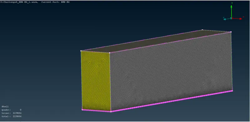
this fluid domain is in rectangular shape
the model is placed a bit ahead from the center.AS VELOCITY AND PRESSURE CONTOUR ARE STUDIED AFTER PASSING THE CAR
TO CREATE WIND TUNNEL(RECTANGLE)
- PLOT POINTS WRT TO LOWER SURFACE OF CAR
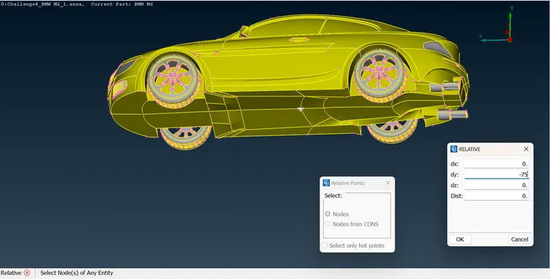
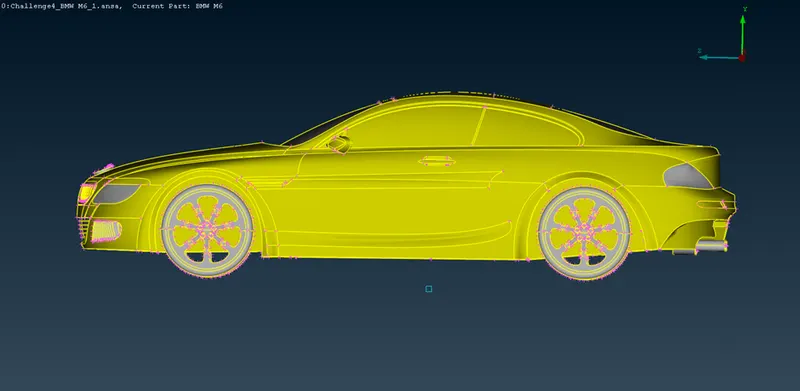
PLOT POINTS FOR A FACE AND HEIGHT
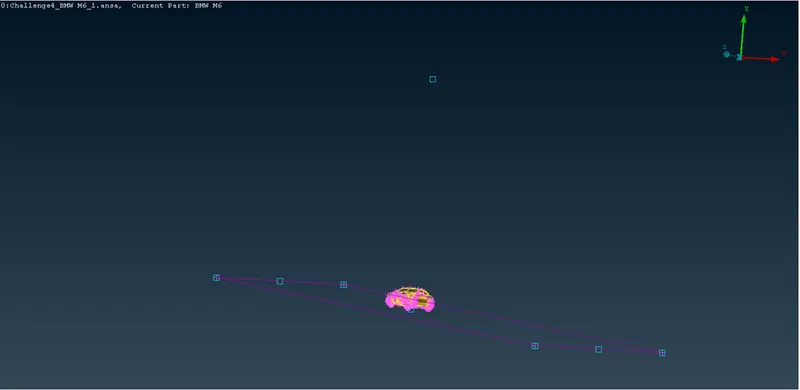
CREATE A SURFACE
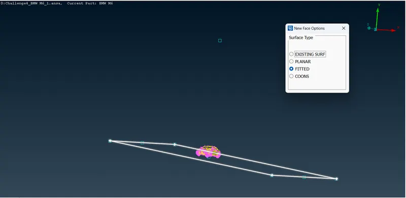
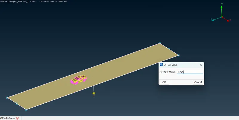
CREATE ANOTHER SURFACE AT OFFSET FROM EXISTING SURFACE
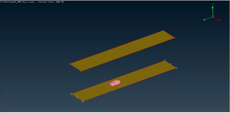
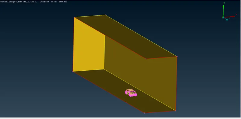
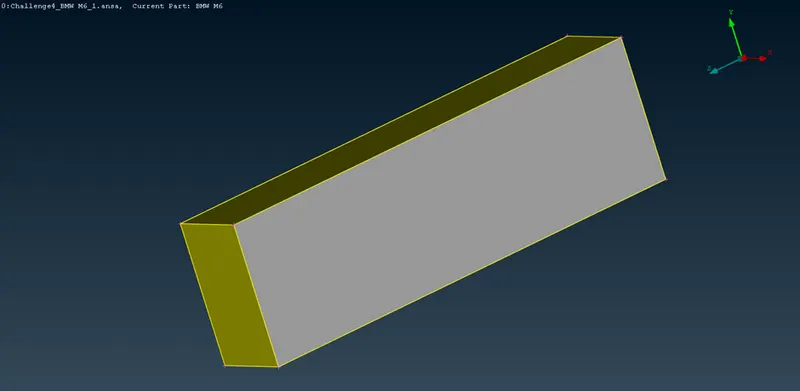
ASSIGN PIDs TO WIND TUNNEL
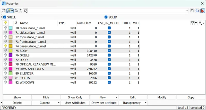
- CREATE NODES ON THE UPPER AND LOWER SURFACES BY USING LENGTH COMMAND
SURFACE MESH SIZE UPPER 100 LOWER 20
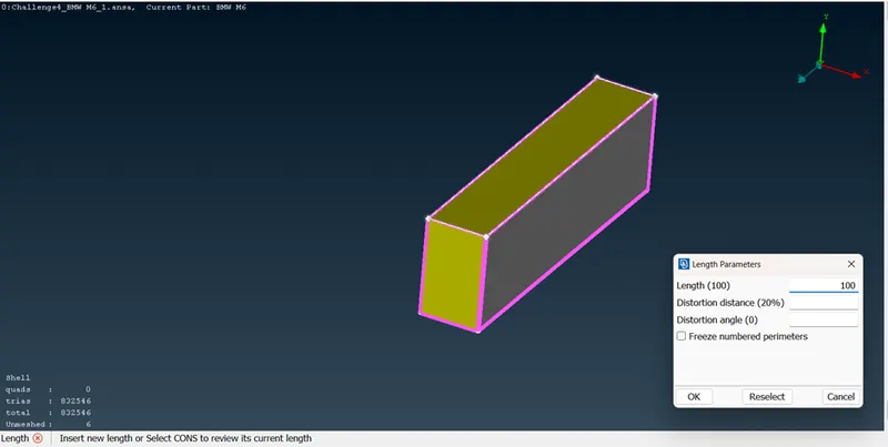
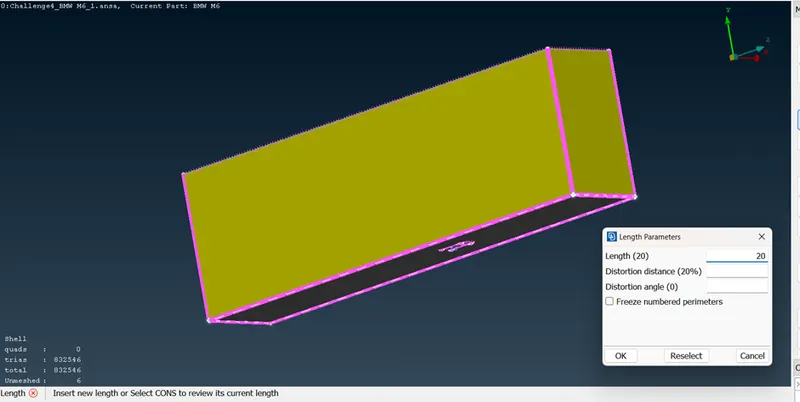
- THE LOWER SURFACE WILL HAVE A SMALLER MESH LENGTH BECAUSE THE CAR IS CLOSER TO THE LOWER SURFACE.
- TO HAVE TRANSITION FROM 100 TO 20 MESH LENGTH ON THE REMAINING 4 SURFACES
SPACING COMMAND IS USED FOR THIS
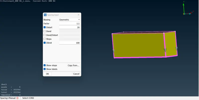
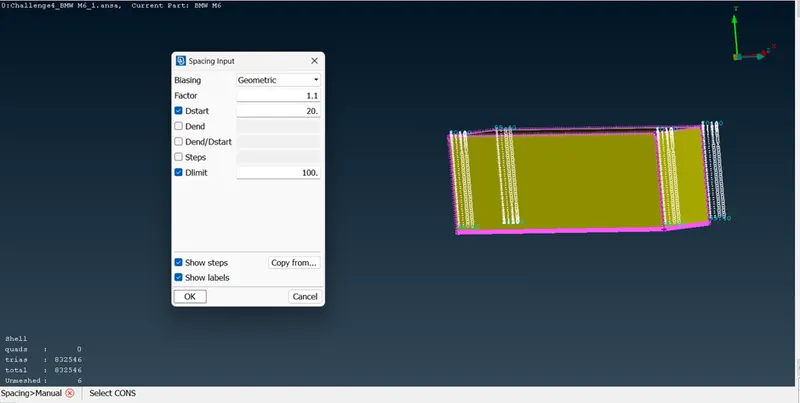
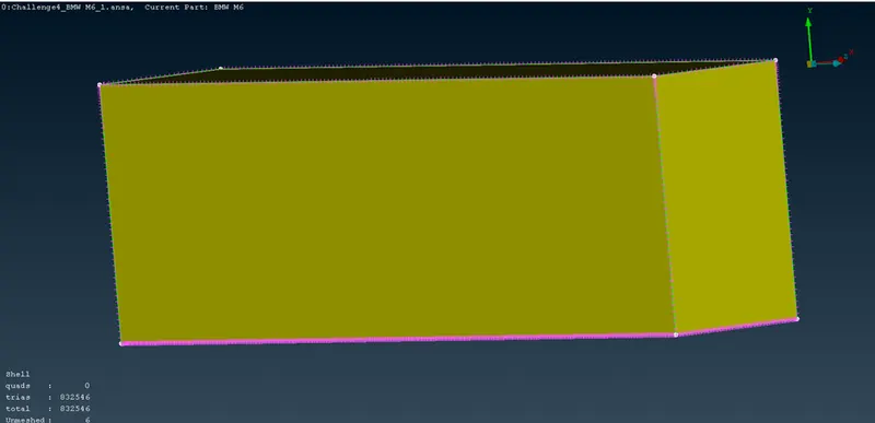
- MESH FOR LOWER SURFACE
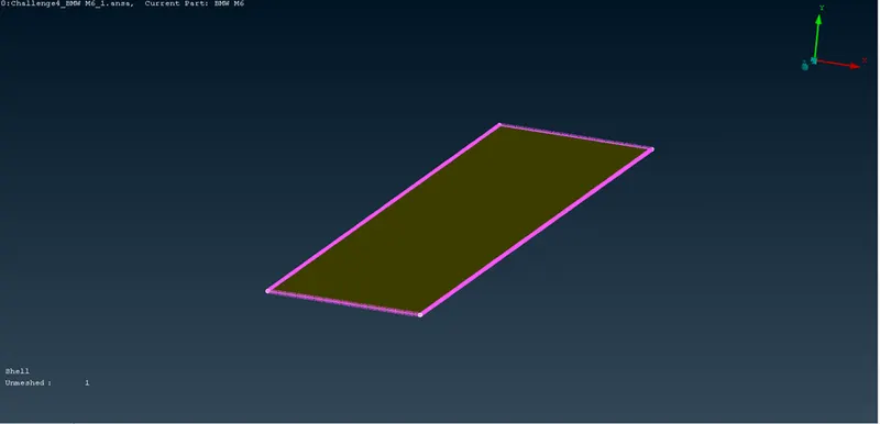
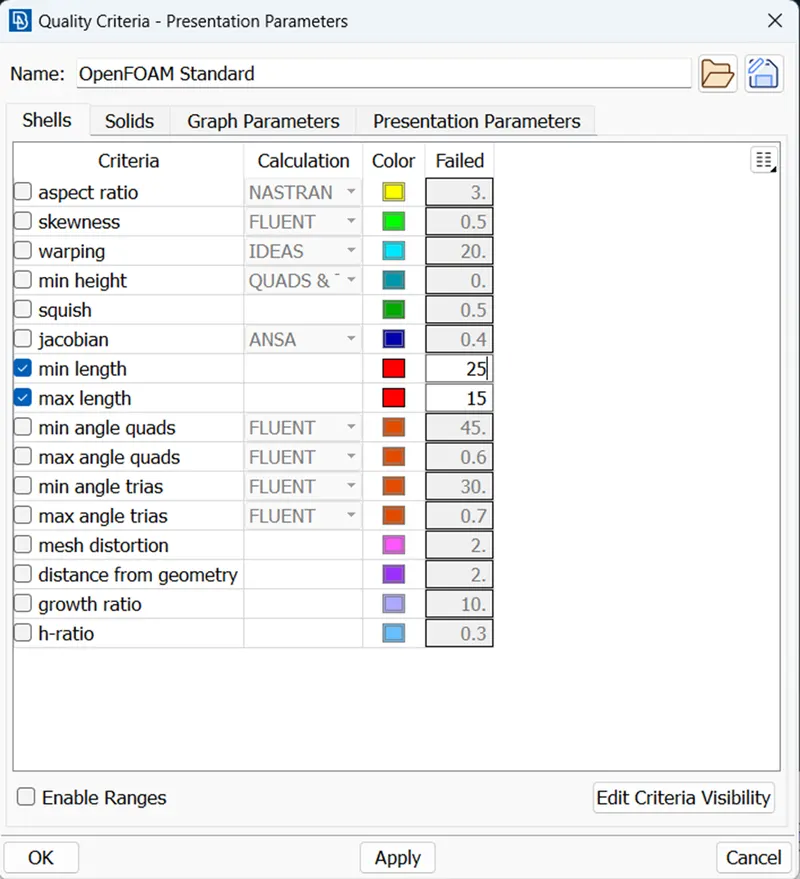
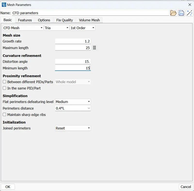
- MESH FOR UPPER SURFACE