Week 4 Challenge : CFD Meshing for BMW car
Introduction:
CFD, the acronym for Computational Fluid Dynamics is the analysis of the systems involving fluid flow, heat transfer and associated phenomena such as chemical reactions by means of computer- based simulations. The technique is very powerful and spans a wide range of industrial and non-industrial application areas.
Week-4 Challenge
Given:
A model of a BMW Car.
Aim/Objective:
|
· Topological Cleanup of the model. · Create and assign PIDs as per requirements. · Perform Surface meshing of the given model along with setting quality criteria parameters. · Construction of a wind tunnel around the model. · Submit the model |
Compulsory tasks |
|
· Volumetric meshing of the wind tunnel |
Optional tasks |
Procedure:
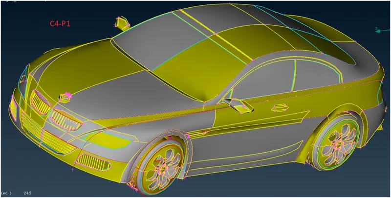
After opening the given model in ANSA, it will look like as shown in (C4-P1).
Preliminary observations:
After opening the model and zooming in, it could be easily seen that the resolution of the cons is not good especially looking at tyres, logo and rear view side mirrors. Additionally, a lot of single cons are also visible.
Step-1:
As there are single cons and triple cons clearly visible in the geometry, let`s hit a TOPO and see if few of them can be merged automatically.
Step-2:
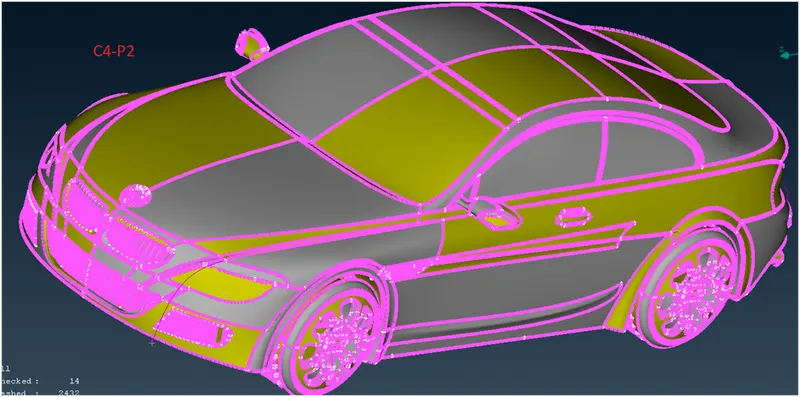
As observed that the resolution of CONS is not good, it is appropriate to increase the resolution first before starting working on the model. The same can be done by FINE option but will take a lot of time as it works on individual cons. In order to save time and do it in one go on the complete model, we should use;
Mesh > Length >Perimeter and give a value of 1mm as the length. The model will look as shown in C4-P2 and the difference will be quite clear from the previous one.
Step-3:
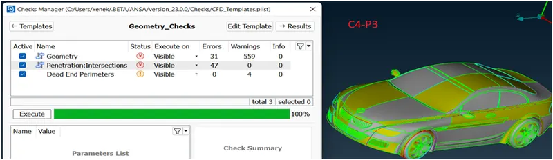
Let`s go for a geometry check. The list of errors can be seen in C4-P3.
Step-4:
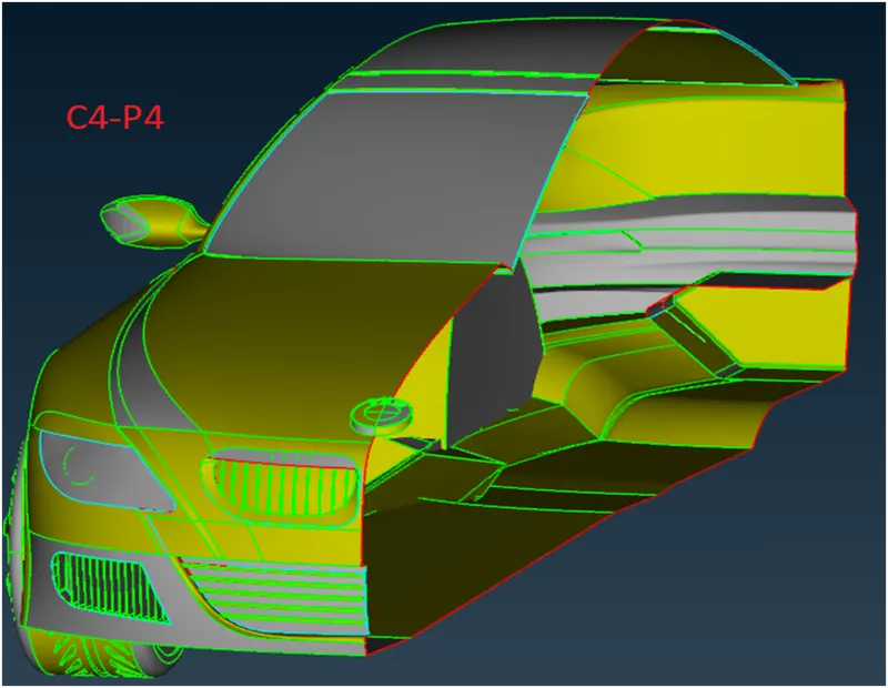
In order to resolve the errors, various tools available in ANSA can be used. However, in order to save time, the given model being axis-symmetric can be cut in two identical halves and work on one part. After finishing the work on one part, it can be mirrored and a complete error-free model can be retrieved back. So, let`s delete the half part of the model in YZ-Plane at the centre i.e from bonnet to boot, except the logo as it is not symmetric. The model will now look like as in C4-P4.
Step-5:
The agenda for making the topological clean-up is to make the main body of the car as a one volume. So, we will have a total 7 volumes ( 1 main body, 4 tyres, 2 silencers and 1 space inside wind tunnel faces). Out of these, only Volumetric meshing of the latter has to be carried out as it is an external fluid flow analysis. In addition, since we are more concerned about external fluid flow, the internal geometry can be altered during the topo clean-up. With these two things in mind, let`s proceed further ahead with our topological clean-up.
Head-light:
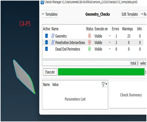
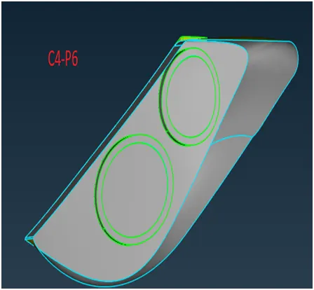
Isolate the headlight and go for a geometric check (C4-P5). On hiding the front face the geometry looks like (C4-P6).
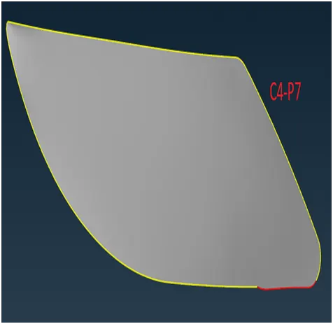
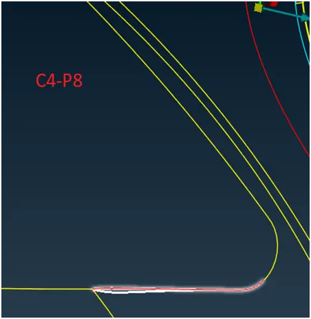
After deleting the inner unnecessary faces as we are focused on external flow analysis, the surface will now look like C4-P7. The red con at the bottom would be dealt with after retrieving back the neighbouring elements. Remove the lock, hit ALL. Paste the red cons to eliminate the error (C4-P8).
Grill-1:
Isolate the grill 1 as shown in C4-P9.
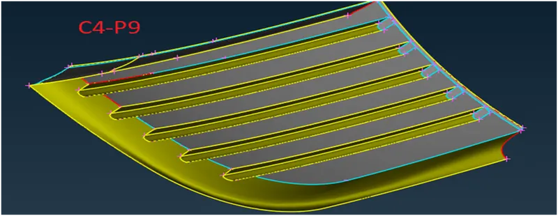
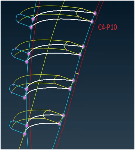
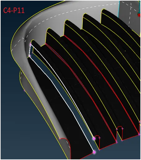
Delete the inner faces that are not required. CONS > Project (C4-P10). Then creating surfaces by FACES > COONS (C4-P11).
After Completing all the necessary operations, the grill 1 looks like as shown in C4-P12 with geometry check also included in the pic.
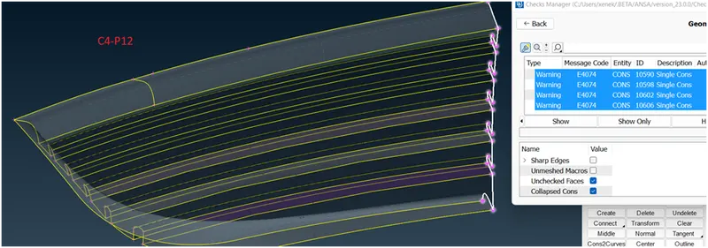
The single Cons are present only at the axis and should not be considered as errors this time. The tools used during the clean-up process are CUT, FACES > DELETE, FACES > COONS as per need. Few unnecessary faces were directly deleted.
Internal random clean-up:
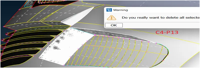
Once the grill-1 topo clean-up is complete, the whole geometry is retrieved back. Some prominent unwanted faces from inside can be deleted directly (C4-P13).
Grill-2:
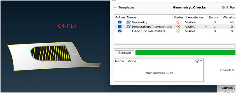
After isolating the grill-2, it looks like as shown in C4-P14 with geometry check also included in the pic.
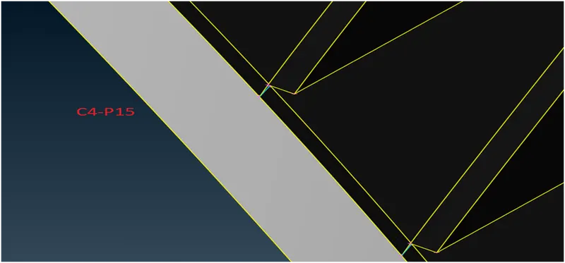
Hit a TOPO to check if any unjoined faces can be joined automatically. It looks like the edges of the grill elements are not properly aligned (C4-P15).
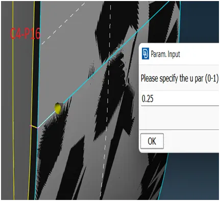
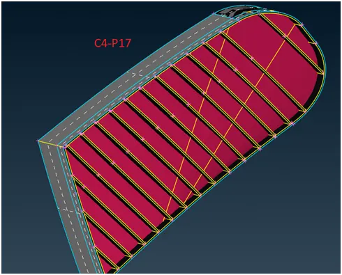
To ensure that the grills are properly aligned, we will try to create an additional vertical surface from inside and delete the parts inside of the surface. For that we can create hot points and then use the cut option to create a cut through out. After that we can create a new surface. After ensuring that the new faces have been created successfully, the glitched surfaces can now be deleted (C4-P16) (C4-P17).
Note: Be very careful while deleting the faces. Use various angles and switch to wire frame mode, if required to target a particular face,con etc.
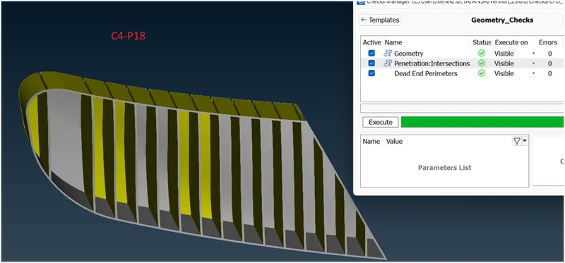
In my case the projection of the hot points was a bit offset and had to use cut option and took me extra time to achieve the desired result. The final shape of the grill 2 is as shown in C4-P18 alongwith a geometry check also.
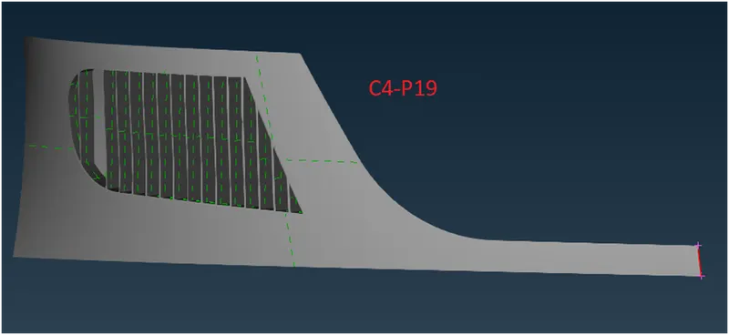
After retrieving the neighbouring part, it looks like as shown in C4-P19. The single Con at the edge is because it is the half part.
Grill-3:
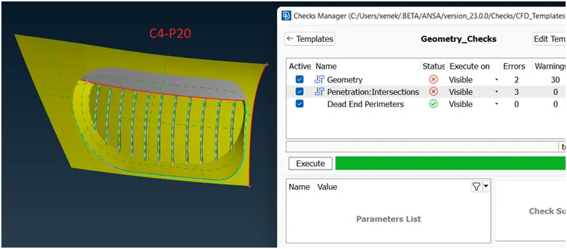
On isolating the grill-3 a pic alongwith geometry check is shown in pic C4-P20.
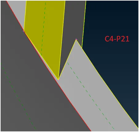
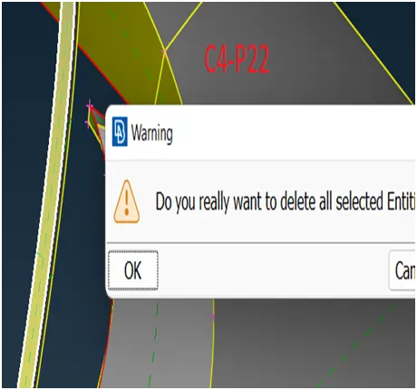
From the inside, delete the unwanted faces. Also, the faces of the grills do not seem to be aligned (C4-P21). Using Faces > Cut to align the vertices of each grill element with each other. Delete the unwanted faces. Then Use the Delete option to erase the back faces of each grill (C4-P22).
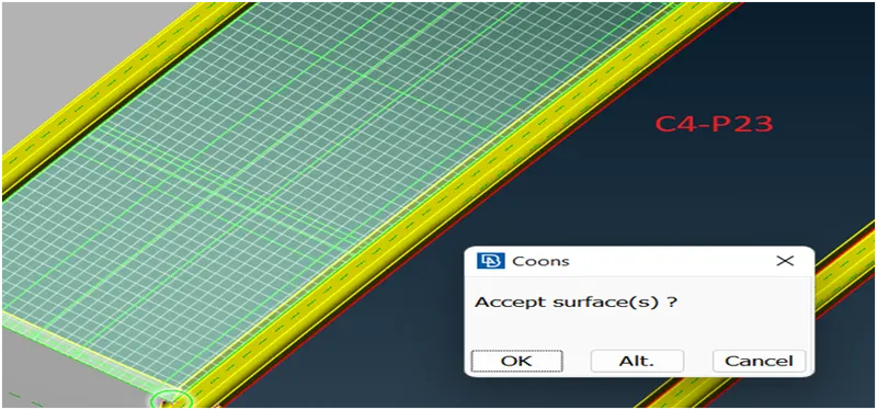
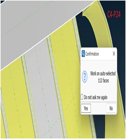
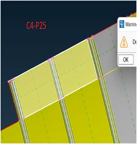
Create the surfaces between the adjacent red cons of the grill for making it one volume (C4-P23). Using Plane Cut (single) option the upper unnecessary parts of the grill are deleted (C4-P24), (C4-P25).
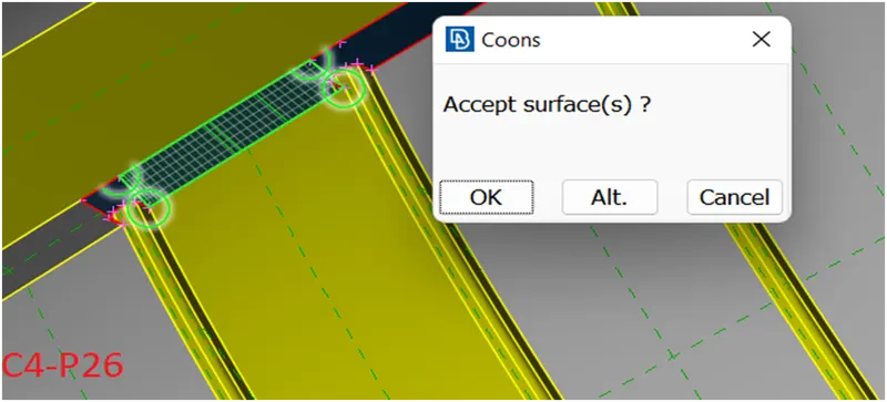
Insert hot points on the single con of top face to make surfaces joining single cons of previously cut grills portion (C4-P26).
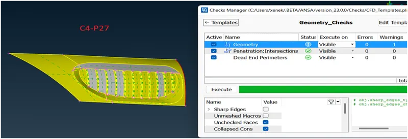
A due care has to be taken while re-constructing the missing faces as balance has to be made between minimum alteration of geometry and at the same time avoiding extremely small faces. The final geometry of grill 3 after clean-up alongwith check is as shown in C4-P27. Again the single cons are due to half part missing and should not worry us.
Logo:
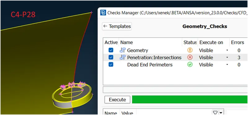
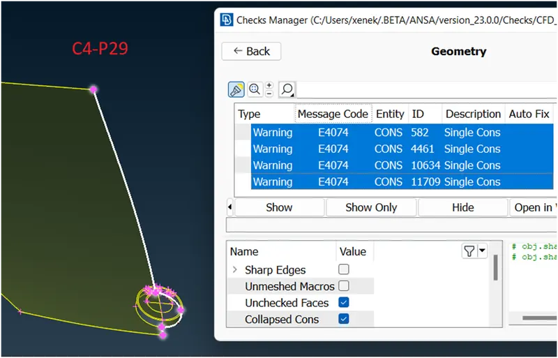
There are some errors visible in logo. On isolating the logo, it will look like as shown in C4-P28. The logo is acting like a separate volume that has to be merged with main body. The final geometry after rectification of errors is shown in C4-P29.
Main Body/windows/mirror:
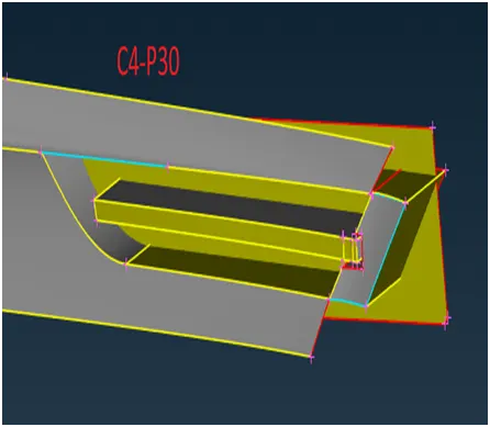
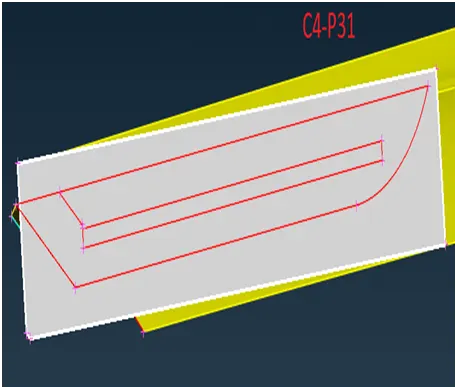
The unnecessary and overlapping parts from the car body are deleted using universal delete option. A special case of interest that looks a bit complicated is deemed to be discussed here in a bit detail. The part has been isolated and looks like as shown in pic C4-P30. Delete the rectangular face from inside (C4-P31).
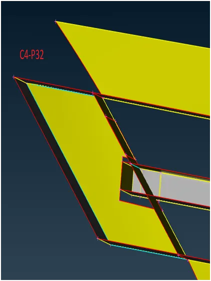
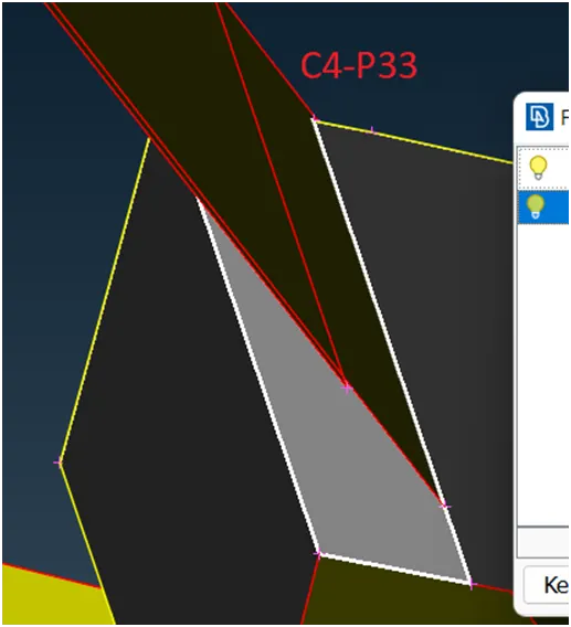
Using Faces > Extend option stretch the bottom inclined face to intersect the top inclined face (C4- P32). Using CUT option, make a cut from hot point of triple con to the red con and delete the unnecessary face (C4-P33).
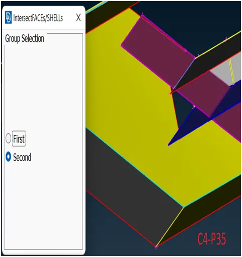
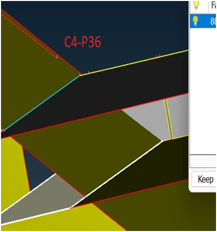
Delete the upper inclined face also (C4-P35). Intersect between the faces as shown in C4-P35. Then make a cut to delete the extra faces (C4-P36).
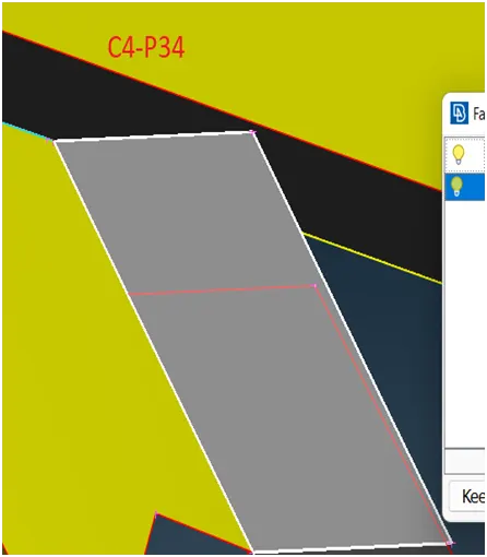
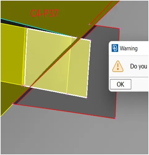
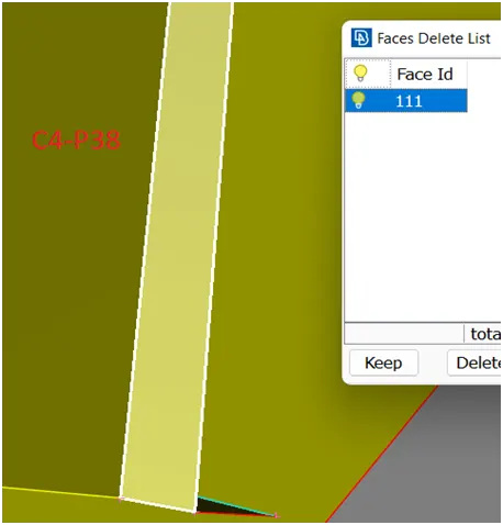
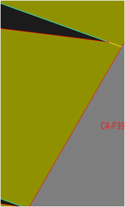
For deleting the upper and lower unwanted faces of the inclined faces, few steps have to be followed . From the front side the two small faces have to be deleted (C4-P37). The small edged face and the adjacent bigger face also will be deleted (C4-P38). Delete the unnecessary hot points on the single con to make a straight edge. Create a Cut as shown in C4-P39.
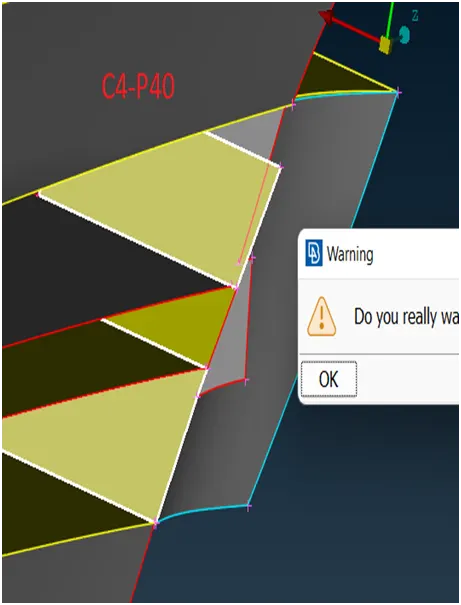
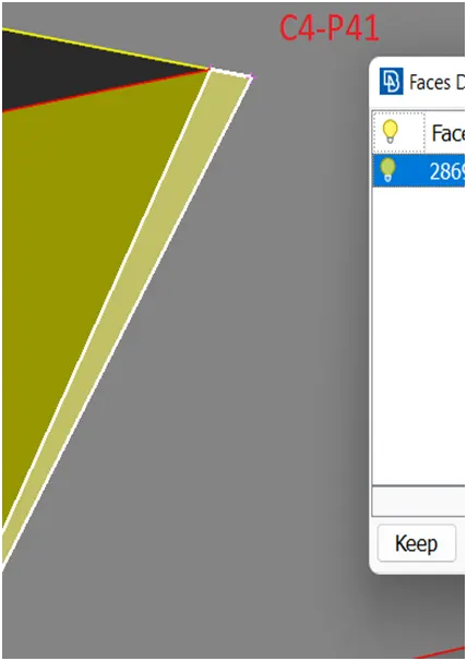
Now the two parts of the extended plane can be deleted (C4-P40). In order to create a face to close the front part, cut has to be made and delete that extra face (C4-P41).
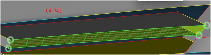
The face can be created by COONS option (C4-P42).
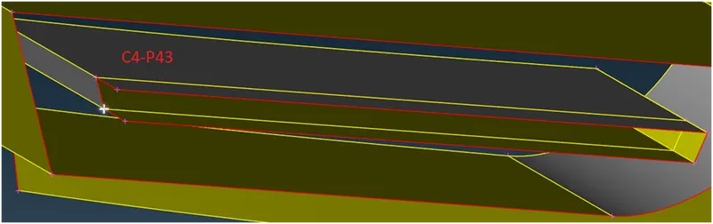
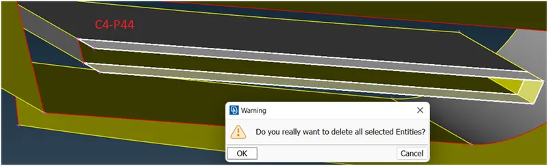
From the inside the extra faces have to be deleted. For that first use project CUT to create a cut on 90 degrees on all faces as shown in C4-P43. The faces can now be deleted as shown in C4-P44.
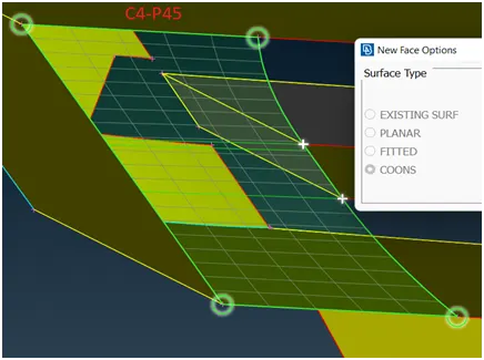
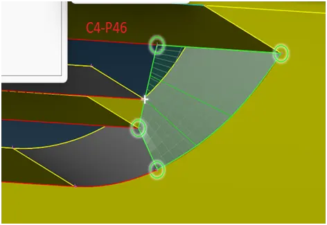
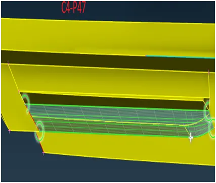
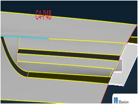
To close the single cone surfaces, faces have to be created in a very careful manner so that no major distortion in the geometry results (C4-P45), (C4-P46) and (C4-P47). From the front side remove the unnecessary small face with single Cons and a needle face highlighted by a triple con (C4-P48).
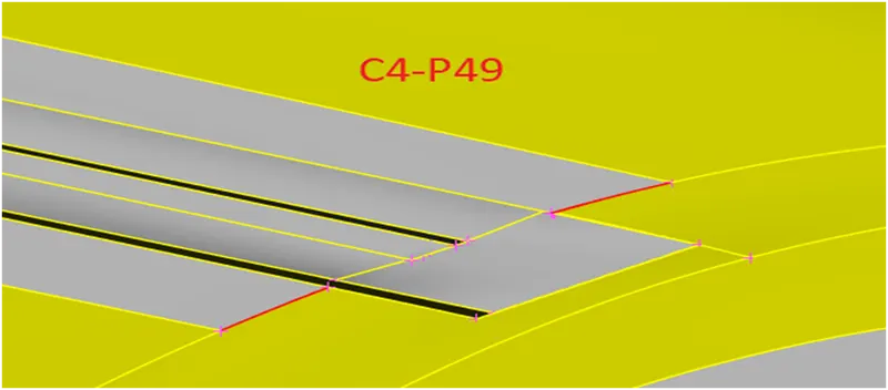
The geometry seems to be clean now. So, hit ALL and retrieve back the elements. The two red cons may appear in the neighbouring elements (C4-P49). On zooming in, a crack can be found. If constructed like this, it will result in needle shaped face and skewed elements can come later on. So, delete it and construct a bigger face.
Tyres:
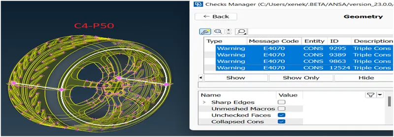
On isolating the tyres and locking them carry out a geometry check (C4-P50).
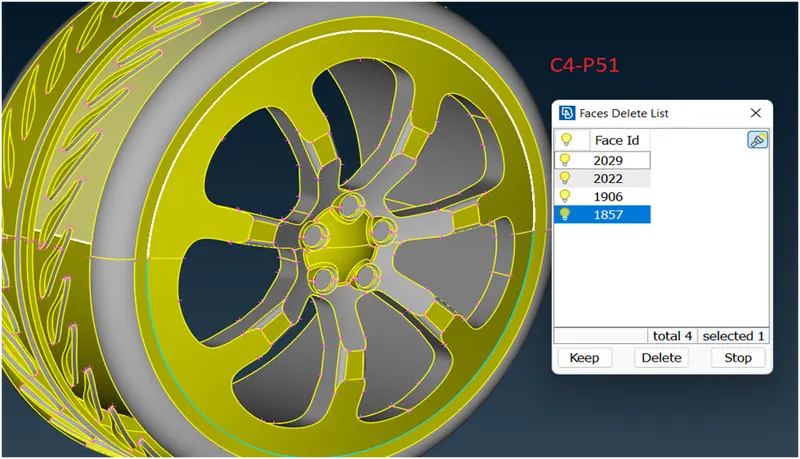
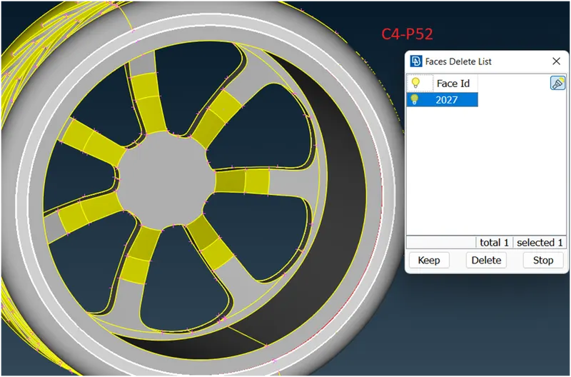
Hide the outer surface and delete the extra faces from inside and beneath (C4-P51). Delete the adjacent face to circumferential single cons from back side (C4-P52).
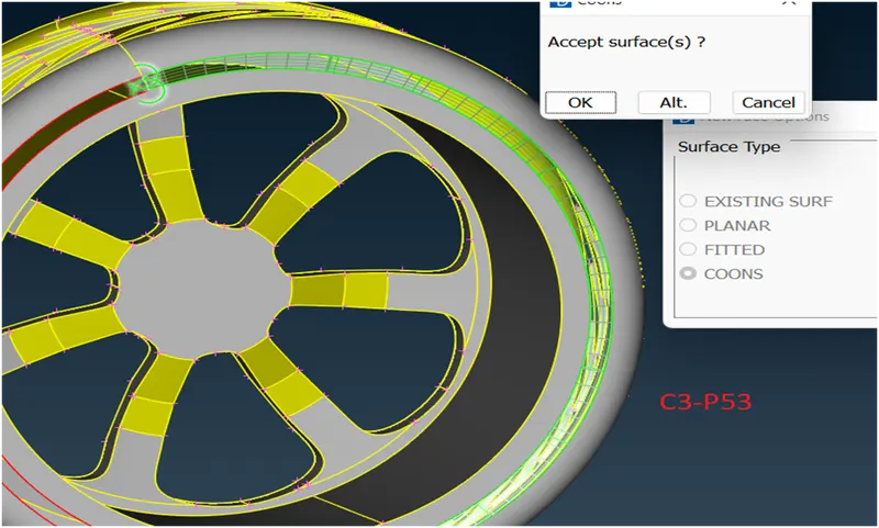
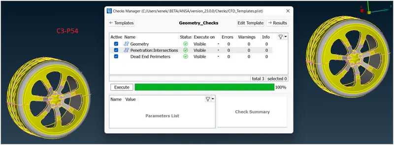
Create a new face as shown in C4-P53. Hit ALL and repeat the process for other tyres. Go for a geometry check (C4-P54). Remove Lock and hit ALL to retrieve back the elements.
Floor:
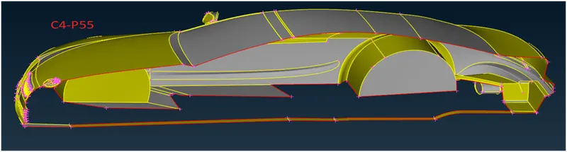
The floor should be dealt with by taking into consideration that all the unnecessary internal faces/intersection faces have to be removed and taking due care when dealing with exhaust. There are other ways to keep a guiding line. I, however, kept a small face at the centre as a guiding line and rest of the unnecessary and intersecting faces have been erased (C4-P55).
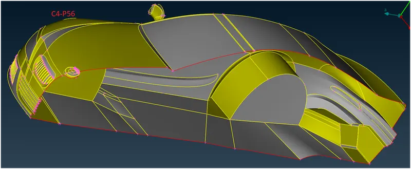
The final floor after topo clean-up is shown in pic-56. The most care has to be taken while dealing with silencer part.
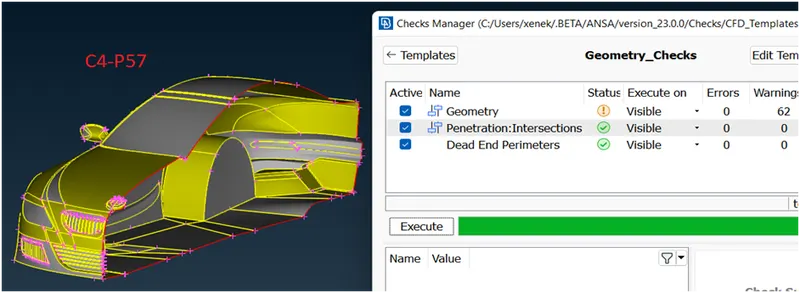
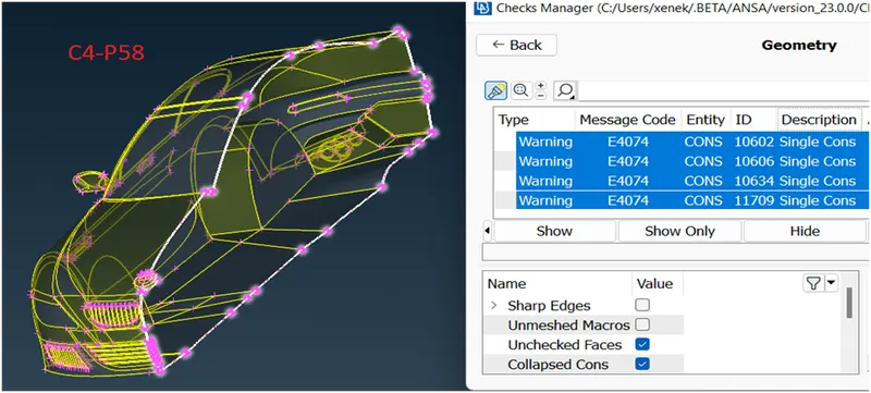
The final geometry check reveals no intersection errors and single cons are only at axis (C4-P57) and (C4-P58). One triple con in logo seems to be an unavoidable one.
Step 6: Assigning PIDs:
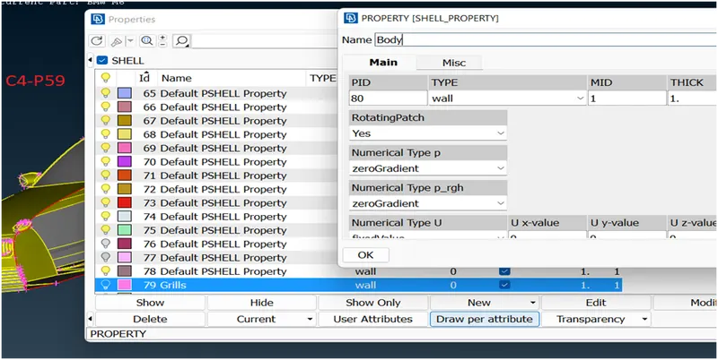
Go to the PID Manager, create new PIDs by the name of following elements (C4-P59):
Body, Lights, Grills, Rims & Tyres, Optical rear view mirror, Windows, Silencer, Logo.
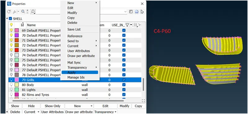
Again Open PID Manager, right click on grills, hit Apply (C4-P60) and select the grills, press the middle button of mouse. Similarly repeat the process for other PIDs also. After assigning all the PIDs click compress and delete the unnecessary default PIDS.
Step-7: Applying quality criteria
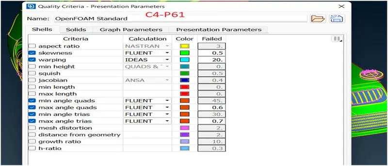
Go to the quality criteria tab from top. It will look like C4-P61.For Current case, we shall only take three quality parameters into consideration- Skewness, min. length, max. length.
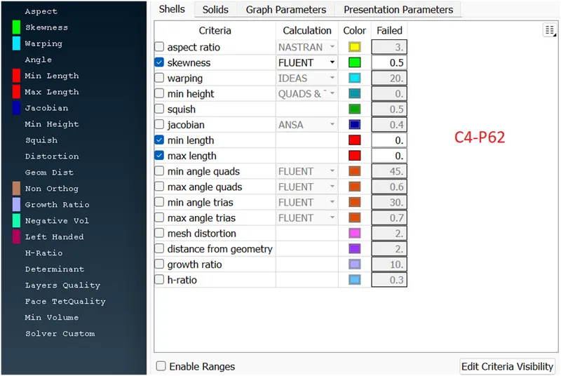
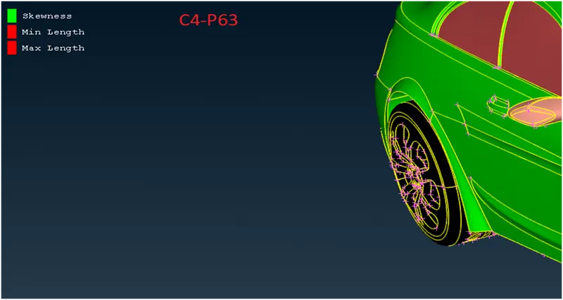
Skewness is a measure of relative deviation of the actual mesh element from the ideal element. Here it will be kept as 0.5. Click Apply at the bottom of the box. Click the hidden mode and all the quality parameters will be displayed on left side of the screen (C4-P62). As we only want the three aforementioned parameters. For that click Criteria Visibility at the bottom of the window and turn off the other parameters. Repeat same for solids also (C4-P63). The colour of the parameters can be adjusted as per our desire. For our current challenge, let`s set a minimum length of 0.1 mm and 7 mm in the quality criteria.
Step-8: Surface Meshing
Always start from meshing of those elements whose target length is the minimum. Here grills and logo have a target length of 1mm which is the minimum. So isolate these elements and proceed with surface meshing.
Go to Mesh > Auto CFD > Perimeters, min. 0.8 mm and max. 1.2 mm > Macros > CFD visible.
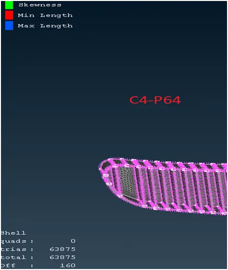
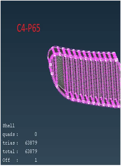
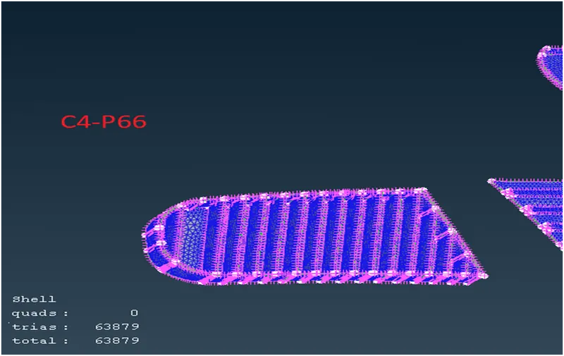
The mesh is generated with 168 Off elements (C4-P64). So, let`s try to improve the mesh. On improving the Off elements only 1 off element remains (C4-P65). This skewed mesh element will be improved by moving grid option. Freeze the meshed elements (C4-P66).
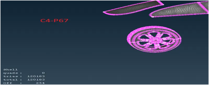
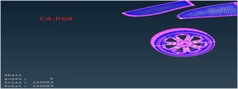
Now, repeat the same process for Rims & Tyres, rear view mirror and windows whose target length is 2mm. Here we will choose a maximum of 2.2 mm and minimum of 1.8 mm target lengths. The meshing is done with 254 off elements (C4-P67). On improving , the Off elements are repaired (C4-P68). Freeze the geometry.
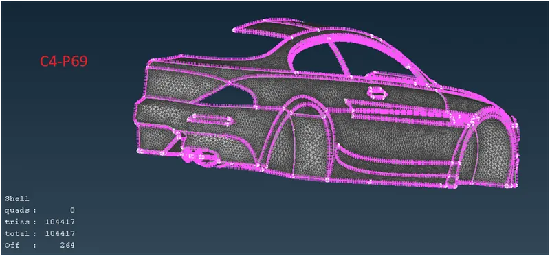
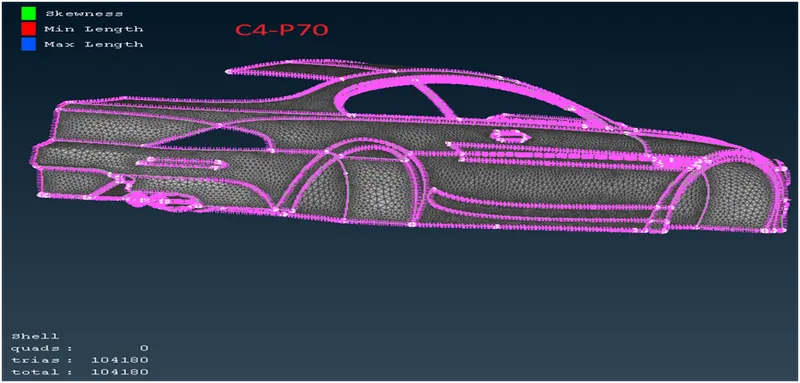
Repeat the process with body and silencer. Use max. of 3.2 mm and min of 2.5 mm. The mesh is generated with 264 off elements (C4-P69). On improving the elements are rectified (C4-P70). Freeze the geometry.
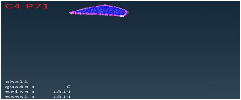
Repeat the process for Lights with a max. length of 4.2 mm and 3.8 as minimum length. The perimeter has already been frozen. So select Macros only. There is no off element (C4-P71). Freeze this also.
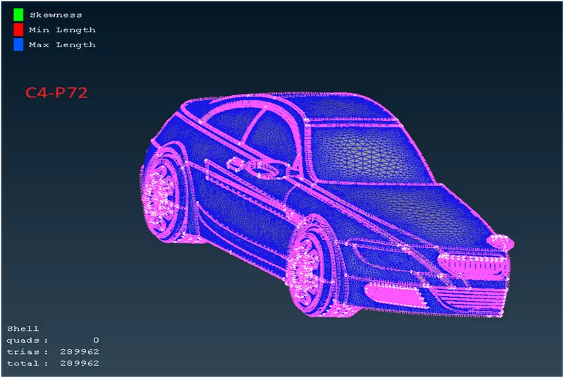
From the PID manager, switch on each meshed component that have been frozen (C4-P72). There is no off element.
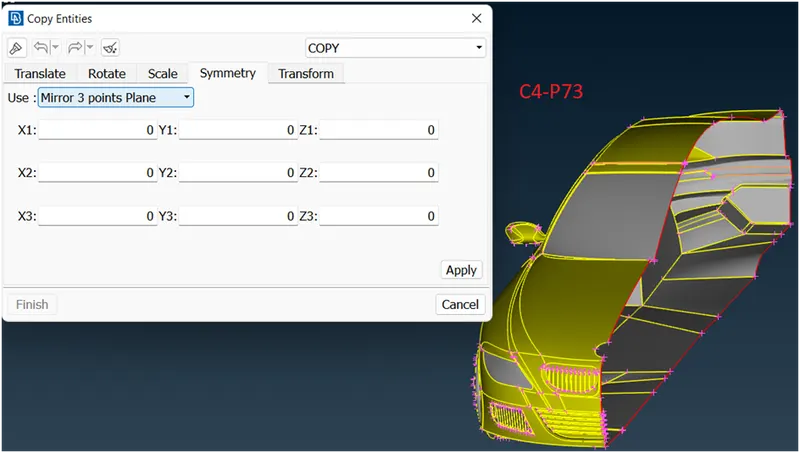
Unfreeze the model and mirror it to fetch the second half and complete the model, except logo. For that use Transform option from top and select 3 point plane (C4-P73). Hit a topo afterwards.
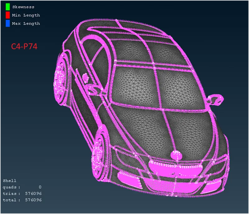
The final surface meshed model is as shown in C4-P74. If any off elements come, either remesh them or improve whatever is feasible.
Step-9: Creation of a wind tunnel
The standard dimensions that have been set for the current model as per previous available literature are: 3x up from the top most point of car, 4x forward from the front most point, 6x backward from the back most point of car, x each from both sides and any appropriate distance downwards from tyres so that there is no intersection. This implies the front face and back face should be at a length of 10x apart and the side faces 2x + width of car distance apart.
X is the length of the BMW model from front to back.
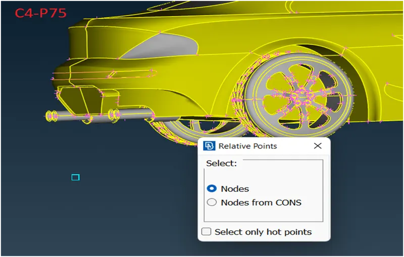
Let`s try to measure the distances as accurately as possible. To do it, let`s create perpendicular points towards the floor at a distance of 200 mm relative to two extreme car points (C4-P75).
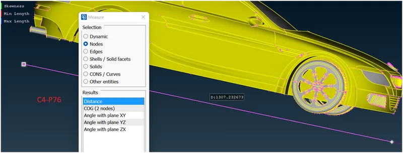
The length of car comes out to be 1307 mm. so our X is 1307 mm. (C4-P76)
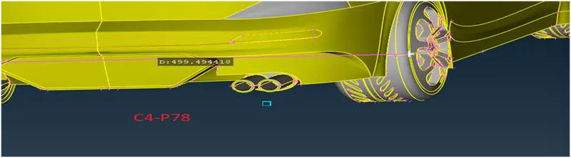
Create a point at the centre of this curve as the new reference point. Now for creating front face of the wind tunnel, a point at a distance of 4 x 1307 + 653.5 = 5881.5 mm relative to central point is to be created. Similarly for the back face of the wind tunnel, a point at a distance of 6 X 1307 + 653.5 = 8495.5 mm relative to central point needs to be created. For constructing the side faces, the separate points can be created in a similar manner i.e 1307 + half the width of car. The total width of the car is measuring 450 mm (C4-P78).
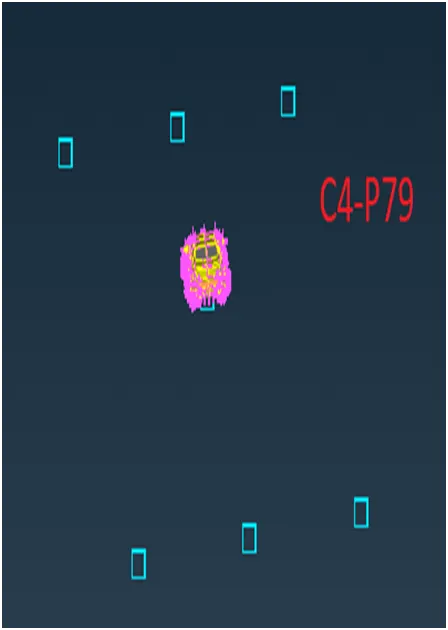
So, the points shall be created at a distance of 1307 + 250 mm = 1557 mm relative to all the 2 points on either sides (C4-P79).
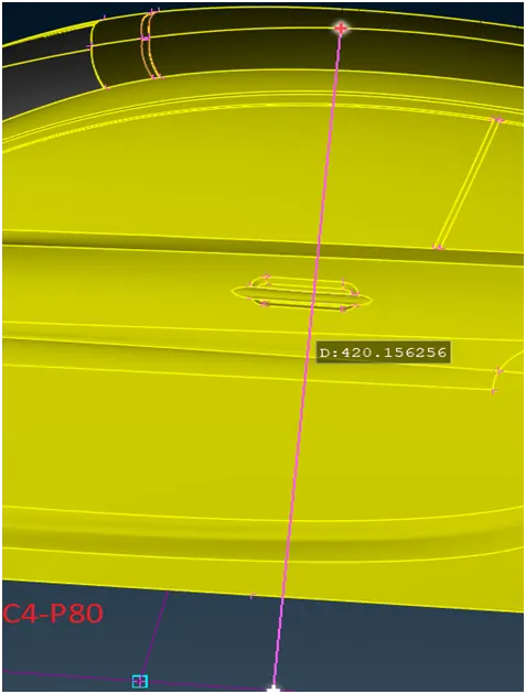
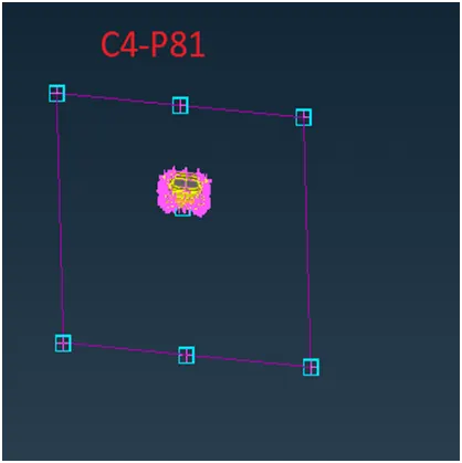
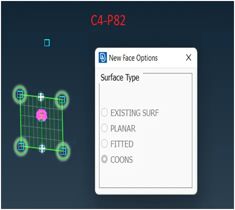
For constructing a top face, first measure the distance from the bottom to be plane to topmost point of the car. After making necessary curves for accurate measurement of the distance, it comes out to be 420 mm (C4-P80). The top face of the wind tunnel has to be 3 X 1307 = 3921 mm from the car roof and 3921 + 420 = 4341 mm from the bottom face. Create a top reference point relative to bottom central point for creating the top face of the wind tunnel. Delete unnecessary hot points and curves. For creating the bottom face, use Curves > Create > Line option to join all the 6 points on the bottom side of the car (C4-P81). Use Faces> New > Coons to create a bottom face of the wind tunnel (C4-P82).
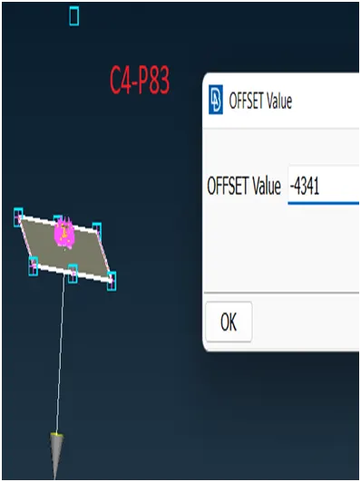
Using Offset option to create a similar face on top at a distance of 4341 mm (C4-P83). Assign a separate PID. Now create the four sides of the wind tunnel using Faces > New > Coons and assign a common PID (C4-P84).
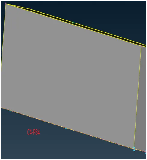
Delete the unnecessary points and curves.
Step-10: Surface meshing of wind tunnel
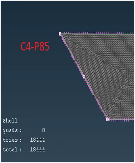
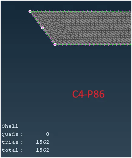
Hide the other PIDS. Target mesh length of bottom face = 50 mm (Max. 75 mm and min 5 mm). Target mesh length of Top face = 250 mm ( Max. 260 mm and min. 240 mm). The four side faces will have a growing mesh and shall be once the meshing of top and bottom faces will be done.
Meshed view of bottom face ( C4-P85) and that of top (C4-P86).
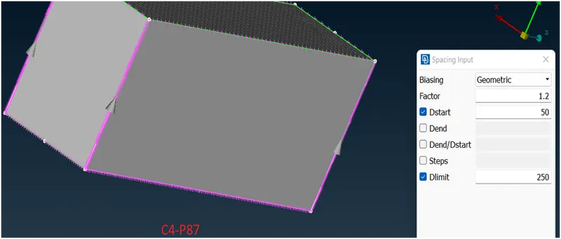
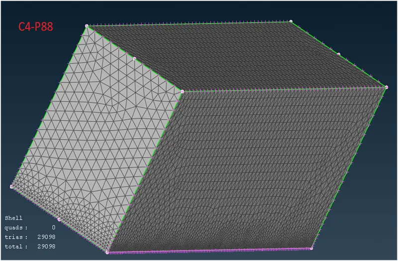
For growing the mesh on four sides, use perimeter > spacing > manual and select edges one by one where the mesh will grow towards (C4-P87). The values should be that of bottom and top faces. Upon CFD visible, growing mesh is generated (C4-P88).
Step-11 : Volumetric Meshing
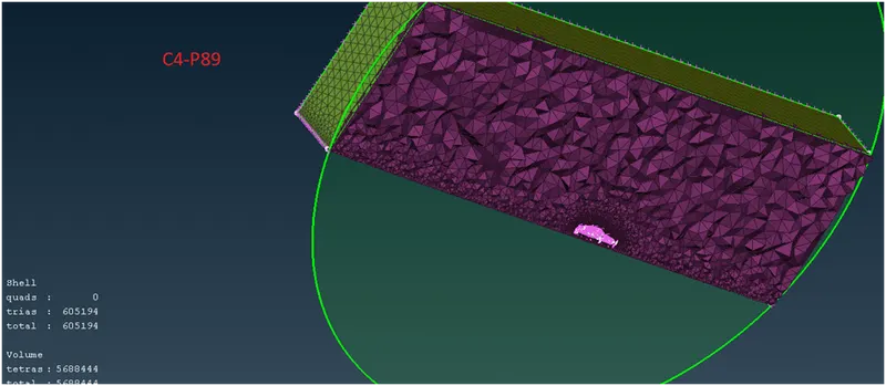
On going for volumetric meshing of inside space between model and wind tunnel, the cross sectional view is given as C4-P89 and the link for the model is : https://drive.google.com/file/d/1tN_SOWQ-DAxO8aFYiB7vzhzrV8O1BQXS/view?usp=share_link
Learning Outcomes:
- Various techniques of topo clean-up
- New tools like Faces > Extend, Offset etc.
- Quality criteria basics
- A realistic idea of the size of the volumetric mesh etc.
Additional self-created tasks:
Do the surface meshing of the wind tunnel with lesser target lengths and proceed ahead with volumetric meshing also. The target length for the bottom face of the wind tunnel has been chosen as 20 mm( 25 max and 5 min). For the top surface, the target length has been chosen as 70 mm ( 80 as max and 60 as min). On completion of surface meshing, the number of elements in the wind tunnel walls came as 250054 in comparison to earlier 29098. The volumetric meshing has also been accomplished with 8819547 tetra elements in comparison to 5688444 tetra elements. The link of the volumetric meshed space is given below for reference:
https://drive.google.com/file/d/1yHvP_E8TePnAACIxG4uuZQwXw7LhsLXD/view?usp=share_link
....................The End.........................