Week 2 Challenge : Surface meshing on a Pressure valve
Introduction:
CFD, the acronym for Computational Fluid Dynamics is the analysis of the systems involving fluid flow, heat transfer, and associated phenomena such as chemical reactions by means of computer-based simulations. The technique is very powerful and spans a wide range of industrial and non-industrial application areas.
Week-2 Challenge
Aim/Objective:
- Task 1: Geometrical errors Check-Up.
- Task-2:Topology Clean-up
- Task-3: Surface Meshing using 3 different target lengths -5mm, 3mm, and 1mm with Tria element. Submit screenshots of all the three cases
- Task-4: Volumetric meshing of the model at last with 1mm target model. Submit the model along with screenshots.
Procedure: Open ANSA>CFD with performance mode 3. Open the file from the desired location
for completing the week 2 challenge.
Task-1:
- After opening the file, It will look as below (C2-P1).
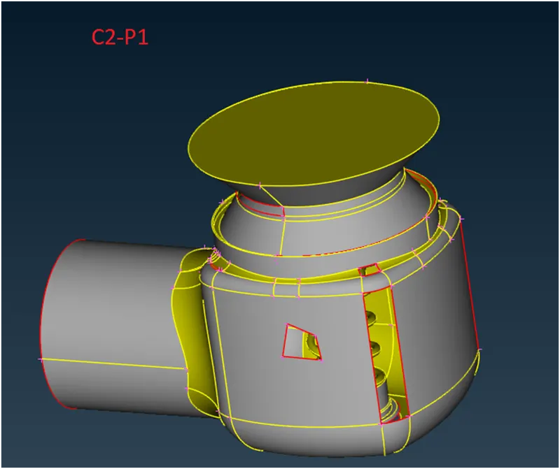
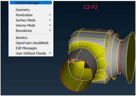
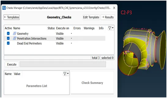
2. Carry out a geometrical check-up. For that, we have to go to the checks manager (C2-P2). A window shall appear (C2- P3). A group of checks will appear viz. Geometric, intersection etc. in turn have subgroups and can be selected from the corresponding boxes.
3. Upon clicking the EXECUTE and keeping the status visible from the box, a list of errors and warnings will appear. If clicked on the error in the list, the same gets highlighted in the geometry. (C2-P4)
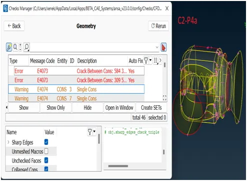
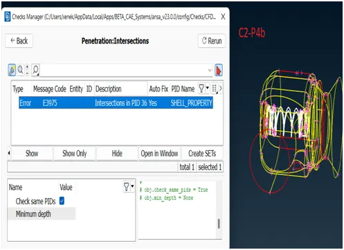
Take-Away/Conclusion: By doing a geometrical check-up, the deficiencies in the model with respect to geometry are highlighted. The important errors in the current model are Cracks/missing surfaces, Single cones, and intersecting faces.
Task-2:
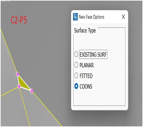
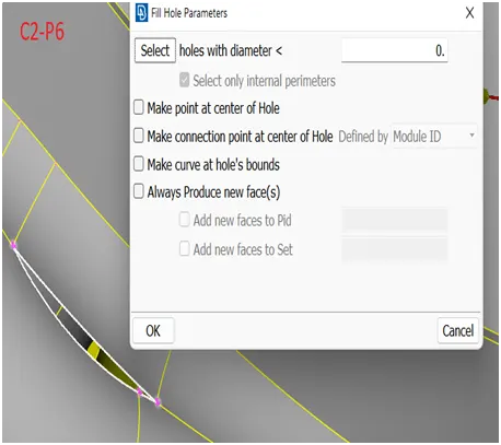
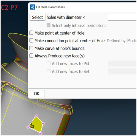
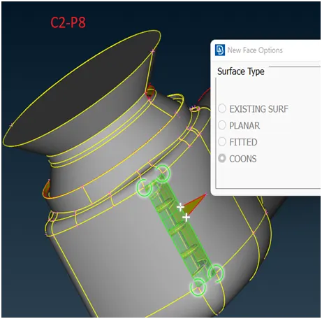
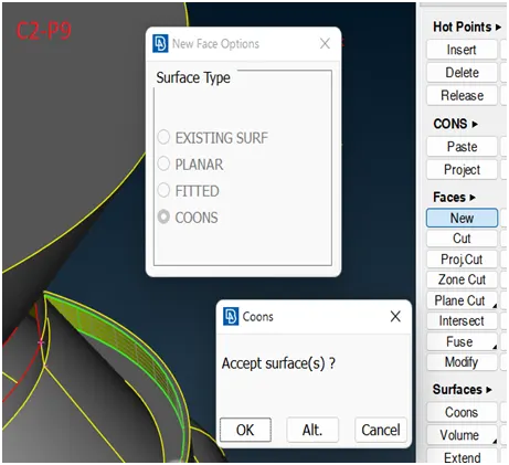
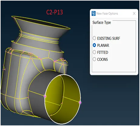
- The missing surfaces/ holes shall be treated first. There are a number of tools for doing that like FILL HOLE, NEW (PLANAR, EXISTING SURFACE, COONS, FITTED). It depends on what suits best for the situation. The ones that seemed to give the best results were selected as depicted in the following screenshots.
2. Topo Cleanup of intersecting surfaces is the next step. To make it easier, PIDs have to be assigned to few components in the model at hand. The same shall be explained below:
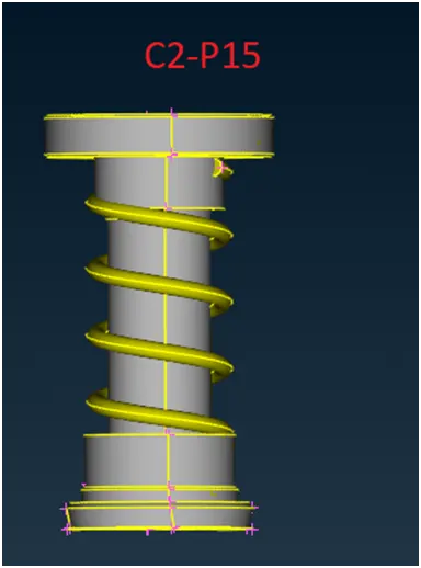
- Using NOT>ENT, hide the outer surfaces and keep only spring & Column (C2-P15). Lock the geometry.
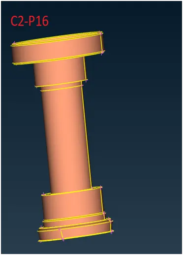
- By Using NOT>PIDR option, isolate the column to assign the PID (C2-P16). Click on SET PID > macros/shells and highlight the column. A window will appear (C2-P17).
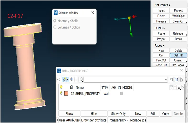
After assigning the name COLUMN under new option, double left-click on the column PID to make it active.
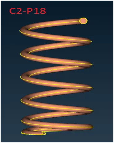
- After that we have to isolate the SPRING to assign a PID. For that use ALL option first to make it visible again. Then with the NOT>PID, it will get isolated (C2-P18). Then repeat the process again as was done for assigning PID to column.
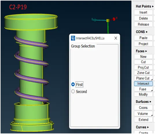
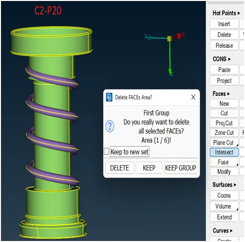
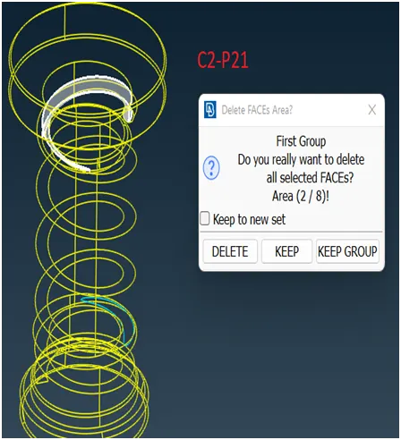
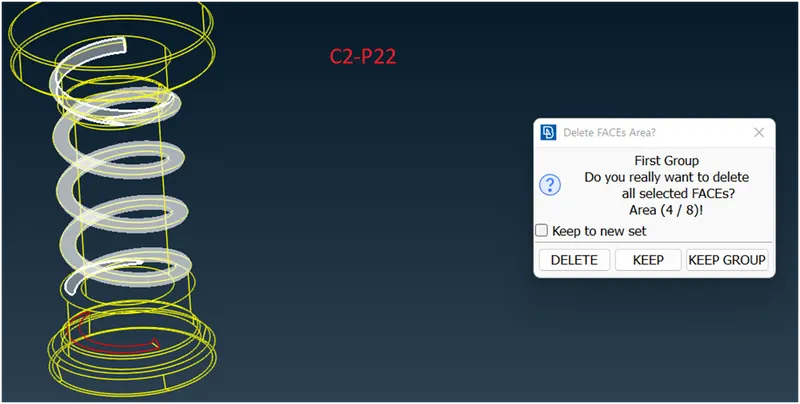
- Now, We can start treating the intersection error using intersect option from the FACES. On clicking the INTERSECT option, a window appears asking for group selection appears (C2-P19). After selecting the two surfaces, it will ask which face to delete or keep? (C2-P20) (C2-P21) (C2-P22).
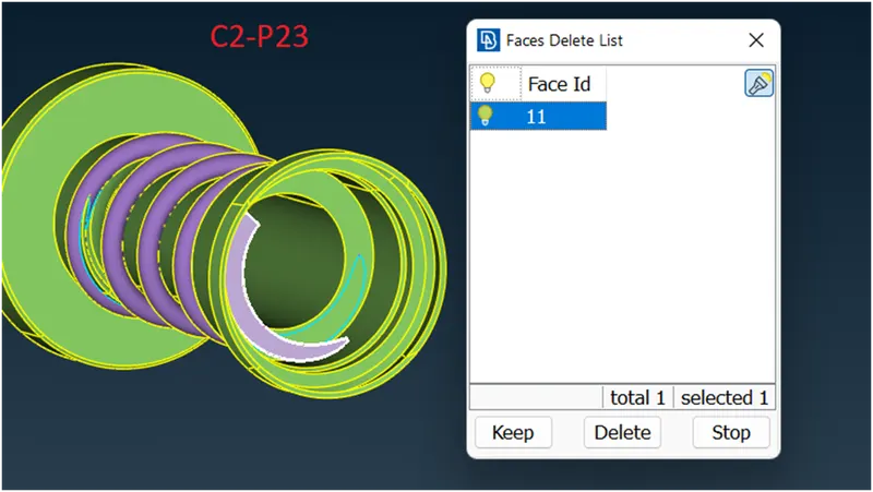
- View the geometry from various angles to see if any unwanted/unchecked faces are there and eliminate them using DELETE option (C2-P23).
- Unlock the geometry to get all the neighboring elements back to visibility mode.
- Go for the geometry check-up again. Here it looks Ok apart from some triple cons that seem to be unavoidable.
Take Away/Conclusion:
During these operations, it is evident that there are various ways to execute a task. However, having knowledge of various tools can make our task much easier.
Task-3:
Surface meshing using target lengths of 5mm, 3 mm, and 1mm.
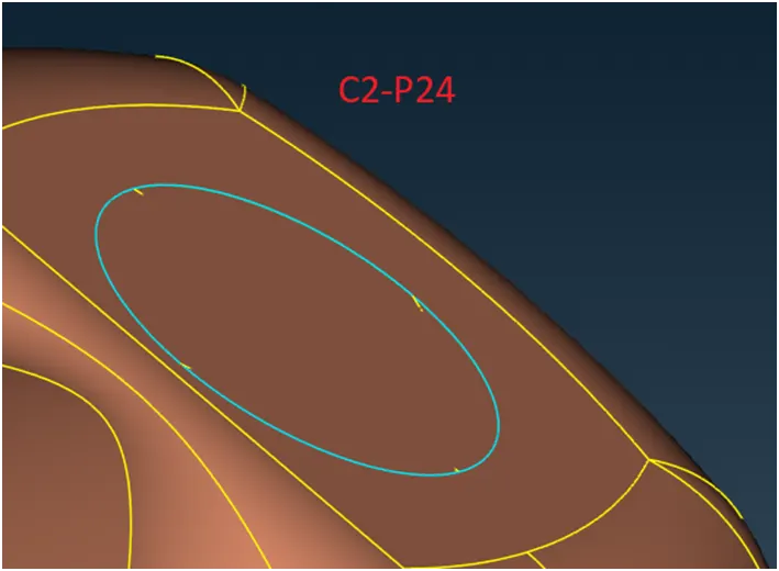
- Before starting the meshing, we need to close the model (although not required for the surface meshing). It is a pre-requisite for Volumetric meshing in ANSA. For that simply create a surface at the bottom using any of the options available (C2-P24).
- Using CFD auto from Spacing > Perimeter > Mesh, a window will appear asking for minimum and maximum target length.
Case1:
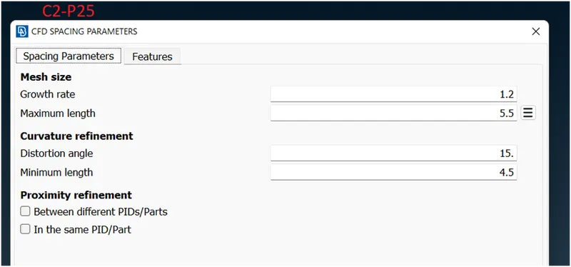
- In first case for 5 mm target length, let`s use 4.5 mm and 5.5 mm as the minimum and maximum target lengths (C2-P25).
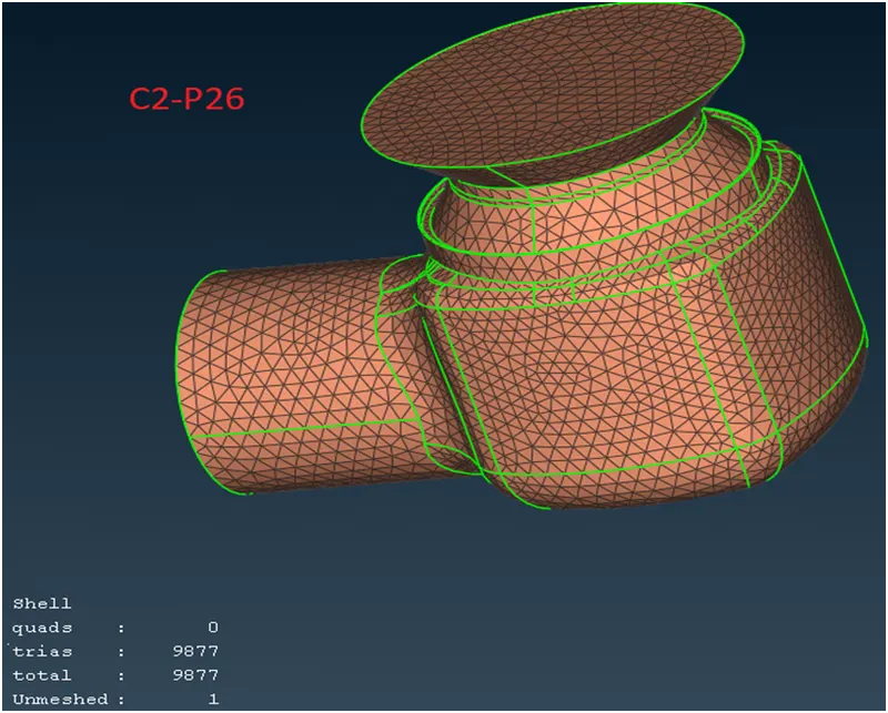
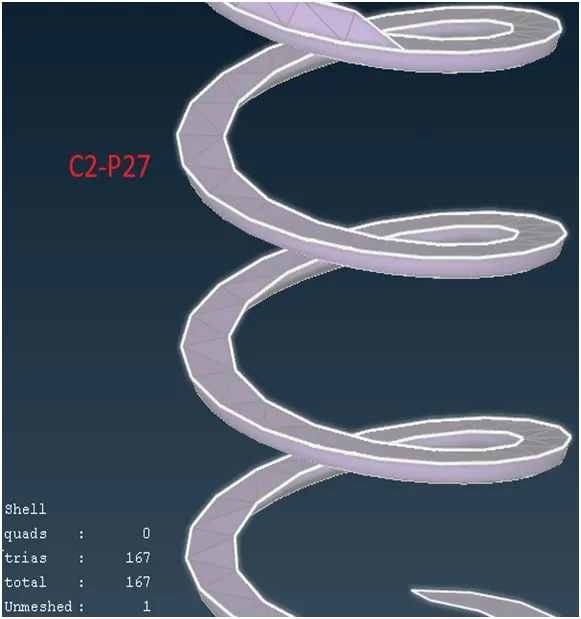
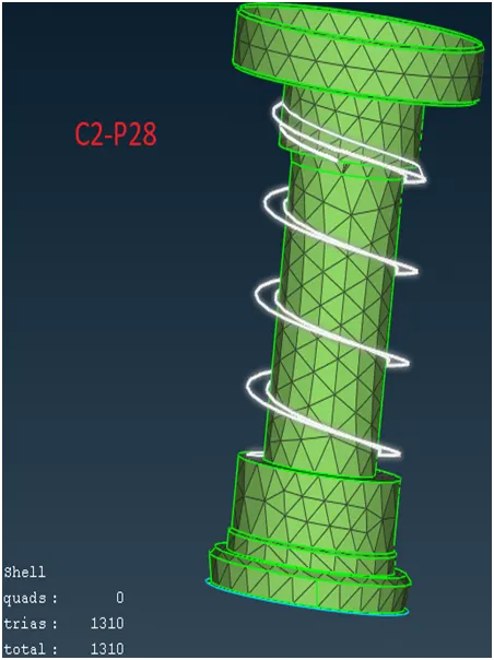
Upon meshing with CFD > Visible, the mesh is generated (C2-P26) (C2-P27) (C2-P28).
Case 2:
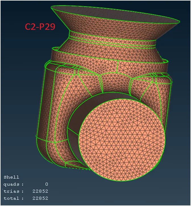
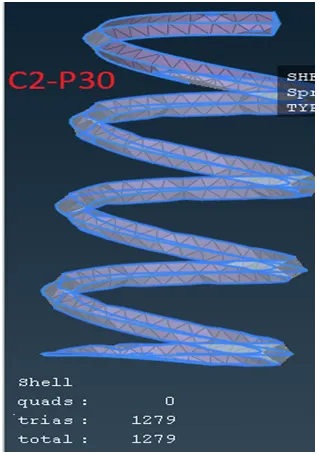
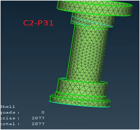
Repeat the same process as in case 1 with a target length of 3mm. For that let`s select 2.5 mm and 3.5 mm as the minimum and maximum target lengths respectively. The mesh shall be generated in the same manner as is depicted below (C2-P29) (C2-P30) (C2-P31)
Case 3:
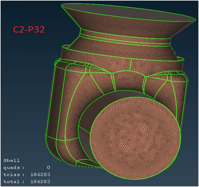
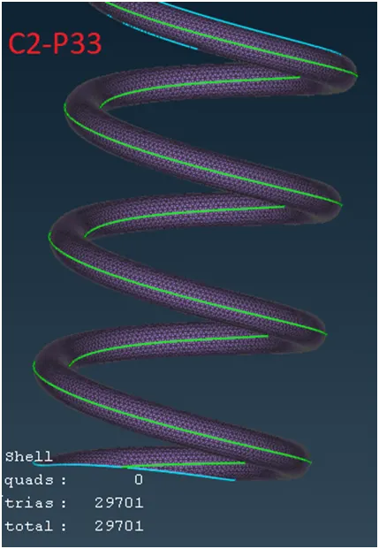
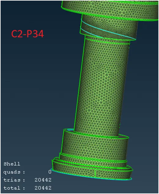
Repeat same process as in case 1 with a target length of 1 mm. For that let`s select 0.5 mm and 1.2 mm as the minimum and maximum target lengths respectively. The mesh shall be generated in the same manner as is depicted below (C2-P32) (C2-P33) (C2-P34).
Task-4:
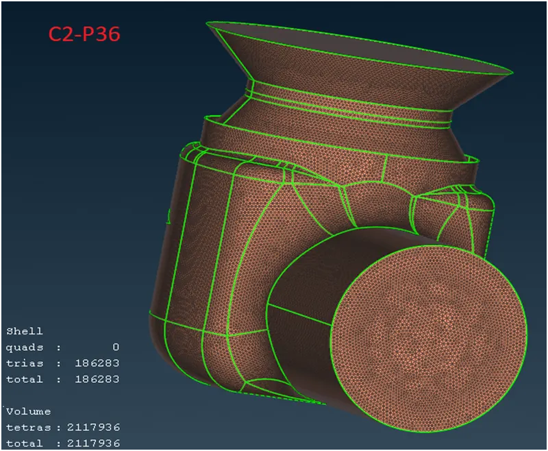
Volumetric meshing using 1mm target length i.e the mode available after case 3 above.
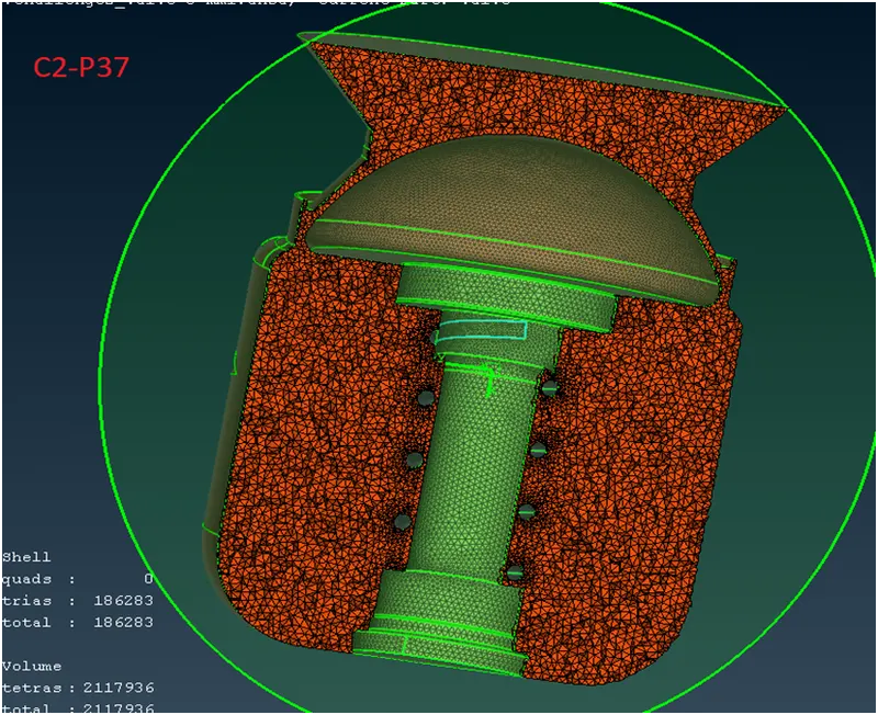
- Go in Volume mesh > define press Ok. A window showing 3 volumes. The desired one to be kept , rest 2 to be deleted as our main aim is to mesh through the inner space of the valve. So, spring and column can be left as it is (C2-P35).
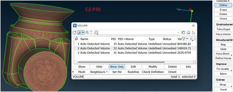
- For the desired one, click on undefined > edit > Tetra Rapid. Then again, click on Tetra Rapid > mesh. The volumetric mesh will be generated (C2-36) (C2-P37).
Take-Away/Conclusion:
During the course of the above task, it has been understood that surface meshing is a prerequisite for volumetric mesh. In addition, the target length is one of the key factors in capturing the geometry. Externally, the geometry might look to be meshed quite well by the selected target length; however, the model needs to be considered in its entirety.
The size of the model is too large to upload. As such a link is shared below to download it.
https://drive.google.com/file/d/1d6IqMBqjLr5eGD-DdmLTB4WOSHprDnz0/view?usp=share_link
……………………………………….The End................................................................