Week 3 Challenge : CFD meshing on Turbocharger
Introduction:
CFD, the acronym for Computational Fluid Dynamics is the analysis of the systems involving fluid flow, heat transfer and associated phenomena such as chemical reactions by means of computer- based simulations. The technique is very powerful and spans a wide range of industrial and non-industrial application areas.
Week-3 Challenge
Given: A generic model of a turbocharger.
Aim/Objective:
- Check for geometrical errors to make appropriate volumes.
- Create and assign PIDs
- Perform Surface mesh with the given target lengths as per the following PIDs:
- Blade stage-1………… 1mm
- Blade stage-2…………. 1mm
- Impeller…………………. 2mm
- Shaft……………………… 1mm
- Turbine casing………… 5mm
- Compressor casing….. 5mm
- Inlet casing cover…….. 5mm
- Volumetric meshing of the model at last. Submit the model along with screenshots.
Solution:
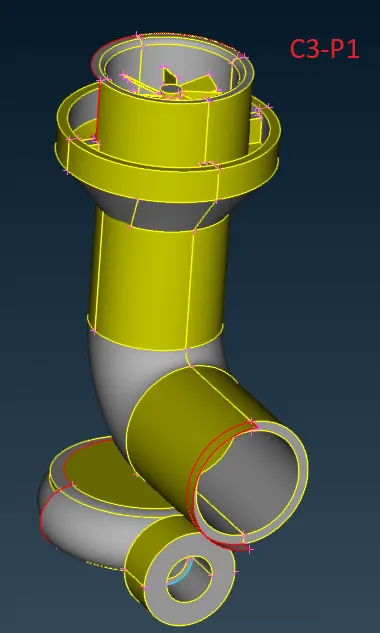
After opening the given model in the ANSA, it looks like shown in C3-P1.
Preliminary Observations/discrepancies and their rectification:
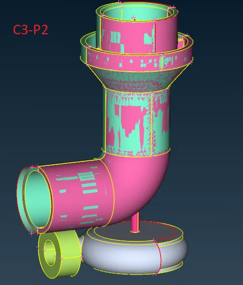
Upon Checking the model in PID mode, glitches can be seen (C3-P2), suggesting overlapping of faces.
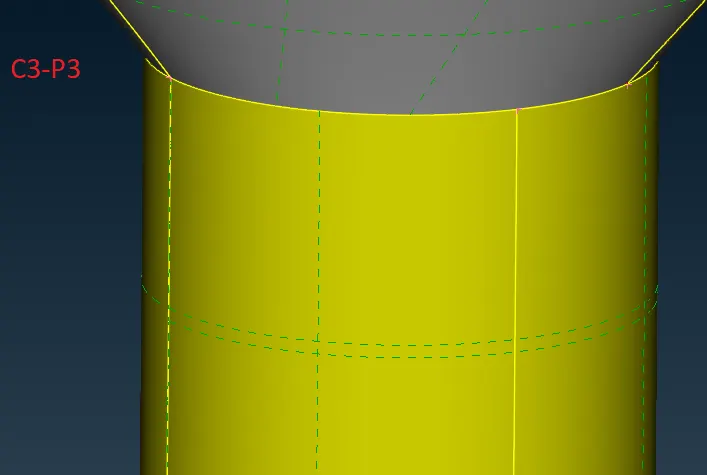
Even in the ENT mode, multiple cross-hatches can be seen on a given face suggesting that overlapping of faces is there (C3-P3).
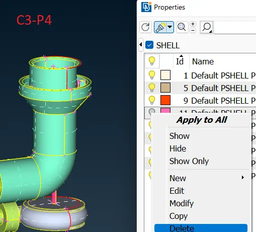
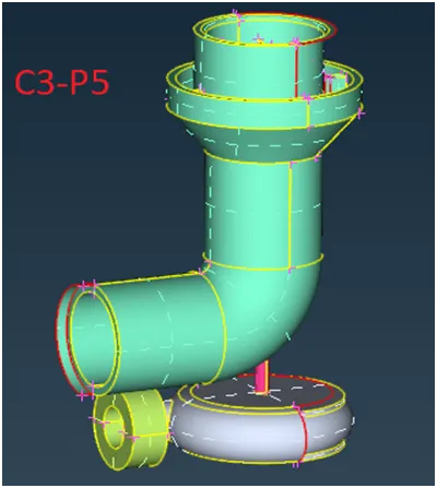
The overlapped surface that is quite conspicuous is deleted first. For that, go to PID, select the pink PID, and delete (C3-P4). After that, the model will look like (C3-P5).
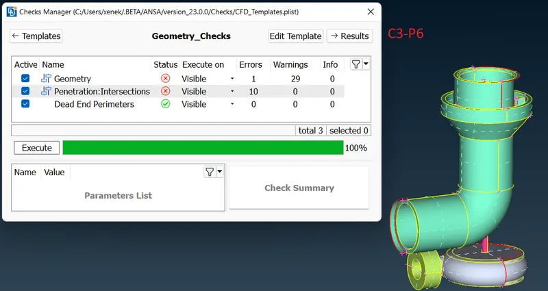
Go for a geometry check to see the list of errors (C3-P6).
Let`s clear the errors one by one starting from the geometrical first using different tools.
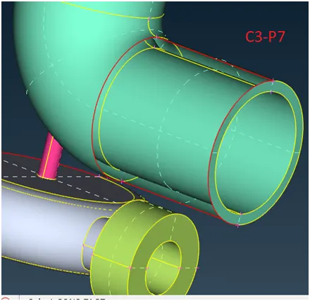
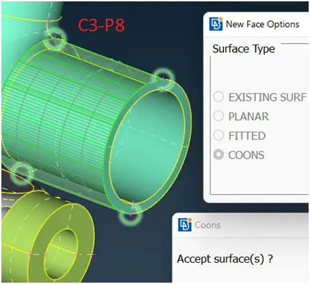
Use Delete from faces option to eliminate a surface (C3-P7). Then create a new face by coons (C3-P8).
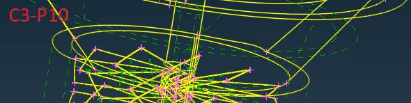
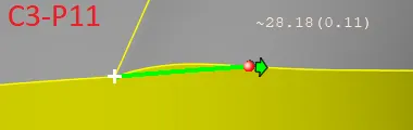
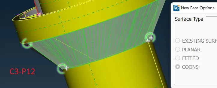
In the picture C3-P9, it is clear that few surfaces are intersecting resulting in single cons. Using Intersect option, it can be checked as in C3-P10. All the single cons are gone. Using the CUT option first, the unwanted parts in the geometry can be isolated/smoothened (C3-P11). Then using Delete and Coons option, a new, smooth, and properly matched face can be carved out (C3-P12).
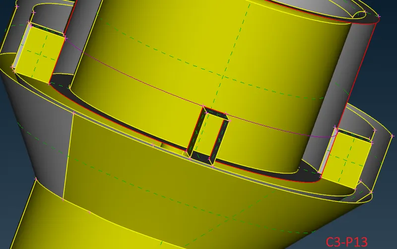
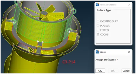
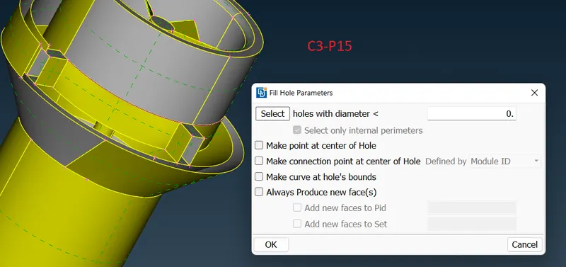
Hide the neighboring elements in the vicinity of single cons with NOT ENT and then using transform option, create 2 new curves (C3-P13).Using Coons option , a new surface can be created (C3-P14). For the bottom surface , FILL HOLE option has been used (C3-P15). Don`t forget to delete the curves that were created earlier with transform option.
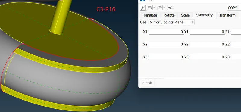
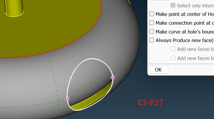
Use Mirror transform option to create the missing half of turbine crossing (C3-P16). The replicated part has a hole that can be filled with FILL HOLE option (C3-P17).
Upon inspecting the single cons in the compressor and turbine casing are no more to be found and so shall focus on intersection errors that are revealed in geometry check.
Using NOT PID, hide the compressor casing so that we can focus on compressor blades and shaft. Lock the geometry and hit a topo (C3-P18).
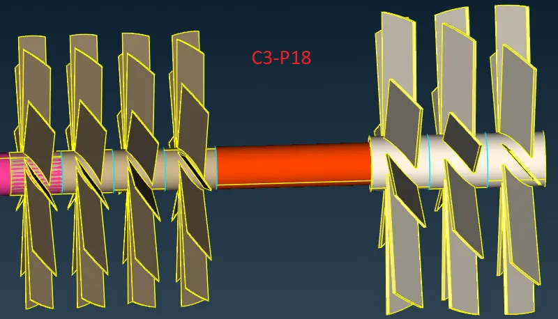
The evolution of triple cons implicate the presence more than two surfaces. Let`s remove the overlapping faces one by one by isolating the stage 1 blades.
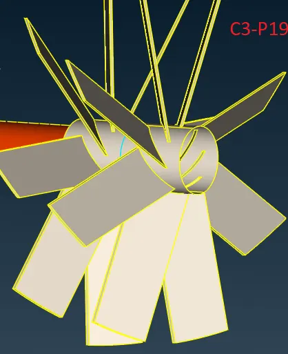
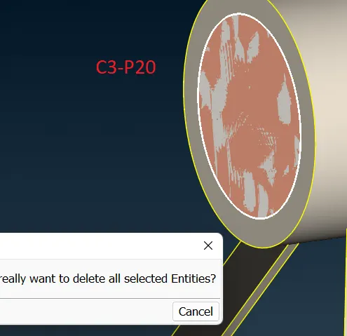
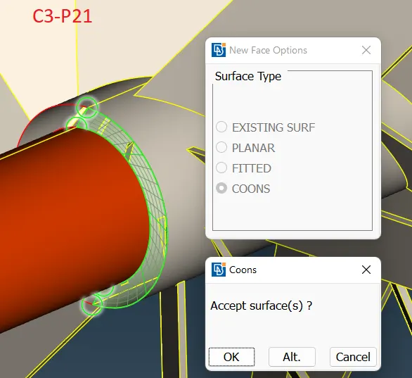
Create a surface between shaft and blade hub to evade the single cons by COONS option (C3-P21).
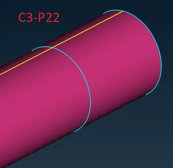
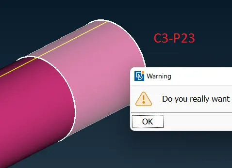
Repeat the process for other blades in the second stage also. The glitched faces on the blade hub shaft can be removed by deleting the part of shaft overlapping with hub of blades. For that use COONS > Project and then delete (C3-P22) (C3-P23).
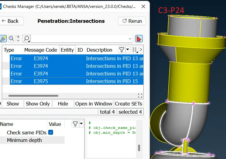
Go for a geometry check and look for intersection errors (C3-P24).
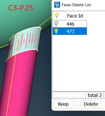
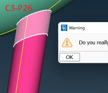
On isolating the shaft that is within casing of compressor where the intersection error was highlighting, we can see a glitched surface that shall be deleted (C3-P25). Then the single cons that are getting reflected is basically due to shaft intersecting with the inner and outer surfaces of the casing. To eliminate this error, we have to delete the part of shaft within the casing. Same can be done by projecting cons on the faces and then deleting it (C3-P26).
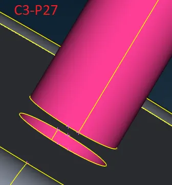
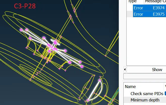
Similar operation has to be done for the part of shaft in turbine casing (C3-P27). The remaining two intersection errors can be seen in turbine section of the model (C3-P28).
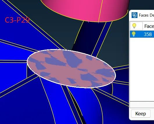
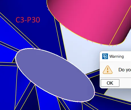
On isolating the neighbouring surfaces, the glitches can be visible in turbine rotor which has to be deleted (C3-P29).The triple cons appearing on the face indicate an extra face present. To delete it, first project cons on the entire circumference and then delete (C3-P30). Hit a topo at last to match the surfaces and eliminate single cons on the circumference of the rotor hub.
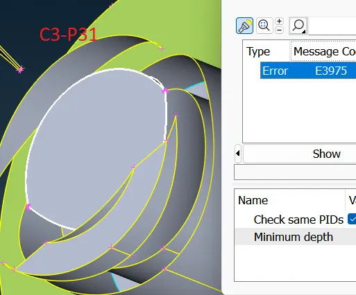
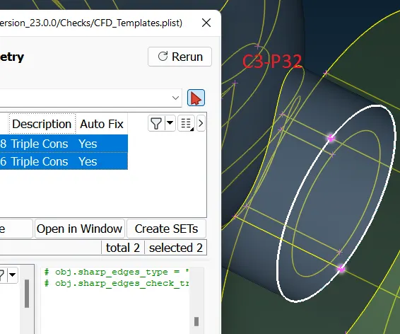
Again go for a geometry check to locate the remaining intersection errors. As is clear from the location of the error, the surface is irrelevant and can be deleted (C3-P31). Final geometry check reveals 2 triple cons as warnings but these being unavoidable cannot be eliminated(C3-P32).
Assigning PIDs:
Divide the model in 7 components and assign a PID for each with the names as described in the challenge. Open PID from top, a window with already existing PIDs is displayed. Start with the Compressor casing. Once it is ensured that all the desired faces are in PID, assign a desired name (C3-P33).
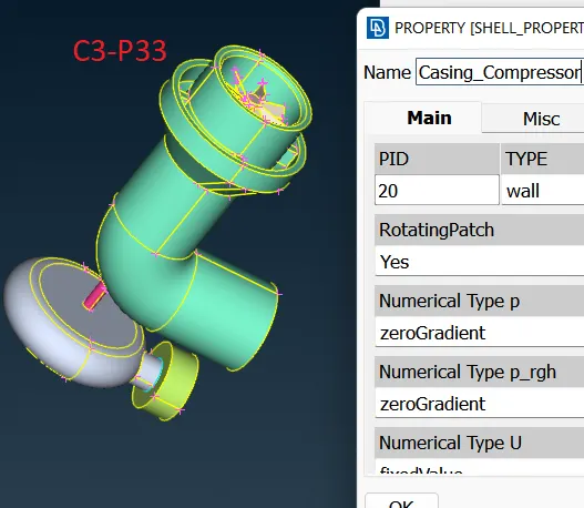
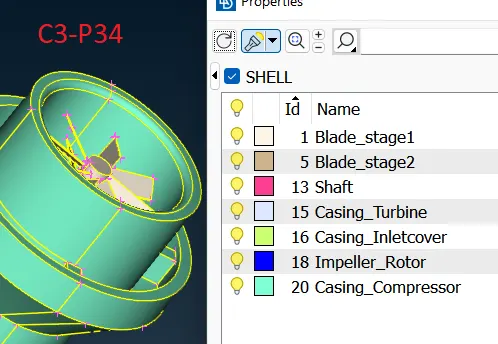
In this case, the PID that have been assigned are: 1. Casing_Compressor, 2. Casing_Turbine, 3. Casing_Inlet cover, 4. Blade Stage 1, 5. Blade stage2, 6. Impeller_rotor, 7. Shaft. The shaft may have by default two PIDs assigned but the same can be clubbed together in a single PID SHAFT. The remaining unnecessary PIDs can be deleted by COMPRESS option at the top (C3-P34).
Closing the model before Meshing:
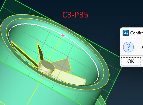
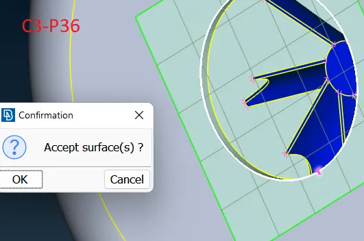
The final step before Volumetric Meshing is to close the model. All Inlets and outlets need to be closed. So. Using PLANAR or COONS or other relevant options, it can be achieved (C3-P35) (C3-P36).
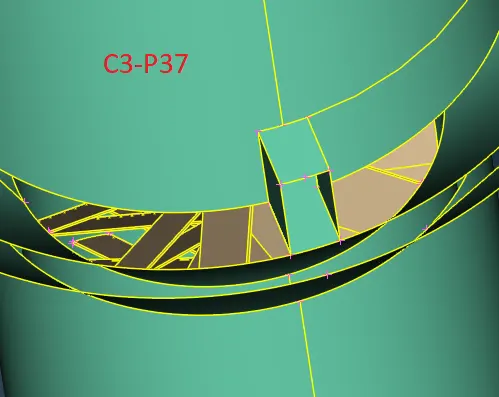
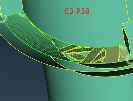
Upon careful observation, the model can be seen to have an opening on the entire circumference in 4 parts (C3-P37). Use COONS option to fill these openings (C3-P38).
Surface Meshing:
The components with similar target lengths shall be meshed together.
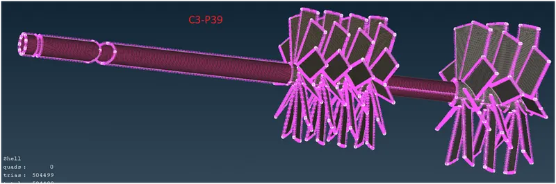
Blade Stage1, Blade stage 2 and shaft ……1mm
Go to Classic Mesh > Perimeter > Auto CFD > Perimeter and Macros;
Maximum….. 1.2 mm, Minimum…..0.8 mm
CFD visible (C3-P39).
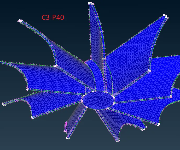
Freeze the meshed elements with FREEZE option in Macros. Repeat the process for Impeller ( Target length 2mm). Select a maximum length of 2.2 mm and minimum of 1.8 mm. CFD visible (C3-P40). Freeze this also.
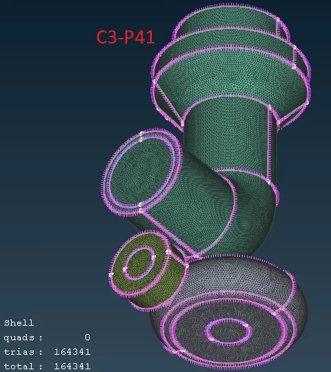
Similarly repeat the operation for other remaining elements for which target length is 5mm.
Let`s select Maximum of 5.2 mm and minimum of 4.8 mm. CFD visible and freeze (C3-P41).
Volumetric Meshing:
Get all the PIDs together as a complete model and UNFREEZE it from Macros option. This is necessary to perform further operations on the model. Go to V.Mesh > Define > Ok. A window will pop up (C3-P42).
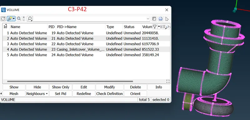
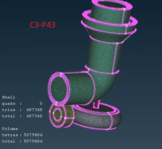
Delete the external volumes carefully and keep the internal ones from the window. Double click the undefined type and select TETRA CFD and mesh each volume from the table. The final Volumetric meshed model is as shown (C3-P43) for which target length is 5mm. Select Maximum as 5.2 mm and minimum of 4.8mm.
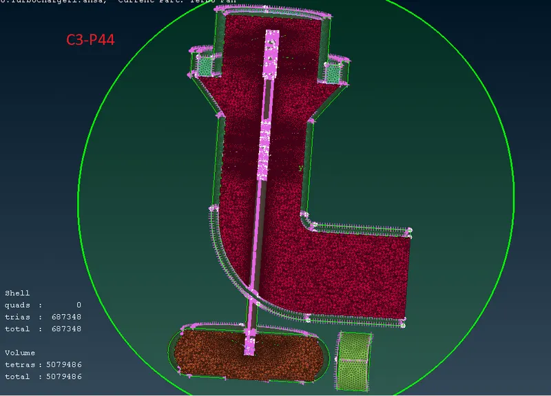
The cut section view of the model is shown in figure (C3-P44).
Conclusion:
The volumetric meshing is only possible when there are no intersection errors and the model is closed. The take –away from this challenge is that individual meshing of the components can be achieved as per the requirements of the geometry.
The link for the final meshed model is given below:
https://drive.google.com/file/d/1uOyS2OfiuJXqfm-KRZ36OA1FD30I72R3/view?usp=share_link
............................................................The End.........................................................................