Week 4 Challenge : CFD Meshing for BMW car
AIM :
To check and solve all geometrical errors for the given BMW car model and generate meshing for the same.
OBJECTIVES :
- Check and solve all geometrical errors on half portion of the car and simplify the components down to single volumes.
- Assign appropriate PID’s to the individual components of the car.
- Perform meshing with the given target length and element quality criteria. Target lengths for the different parts of a model are as follows.
- Body - 3 mm
- Lights - 4 mm
- Grills - 1 mm
- Rims and Tyres - 2 mm
- Optical Rear-view mirror - 2 mm
- Window - 2 mm
- Silencer - 3 mm
- Logo - 1 mm
- After meshing the half model, do symmetry to the other side and make sure the model clears the quality criteria (i.e., off elements should be zero).
- Build a wind tunnel volume around the car geometry and generate surface meshing for the wind tunnel surfaces. Write a detailed report for the same.
PROCEDURE :
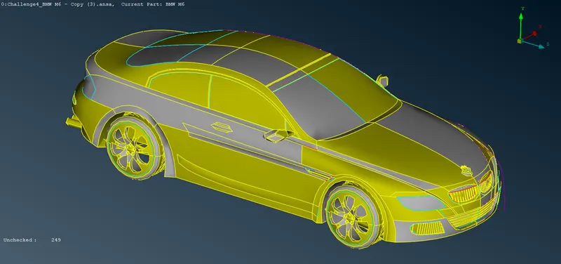
The first and foremost step in the process is importing the BMW car geometry into ANSA. The imported geometry is as shown.
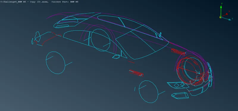
By turning on the wireframe mode, we can observe that there are various errors and overlapping surfaces in the entire geometry.
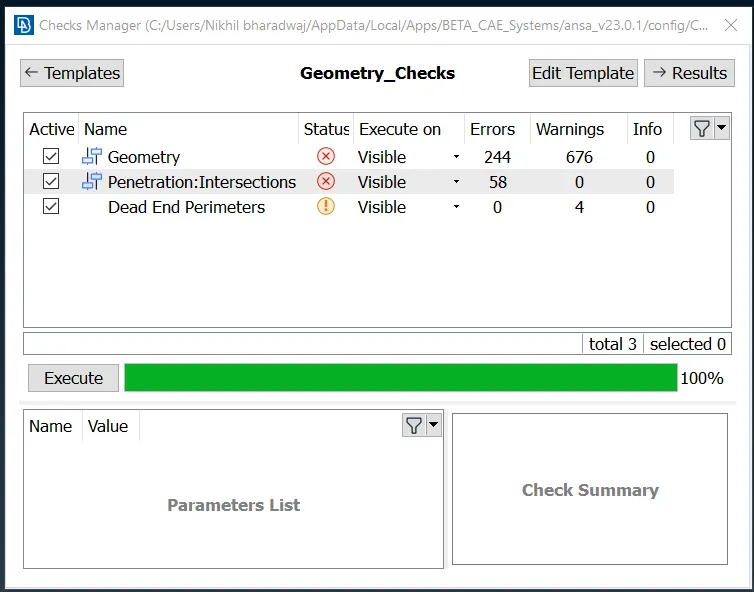
In order to identify these errors, we first run a geometry check. The various errors and warnings are identified as shown.
Also, if we zoom in on the geometry, we can observe that the entire geometry is pretty distorted. In order to solve this, we need to increase the resolution of the geometry. Further, to solve the various errors in the geometry, we need to perform topo cleanup for the same.
TOPO CLEANUP :
In order to resolve the errors in the geometry, we need to perform topo cleanup. First, we refine the resolution of the geometry so as to capture the components in much more detail. We do this by reducing the perimeter and macros length for the whole geometry.
Before :
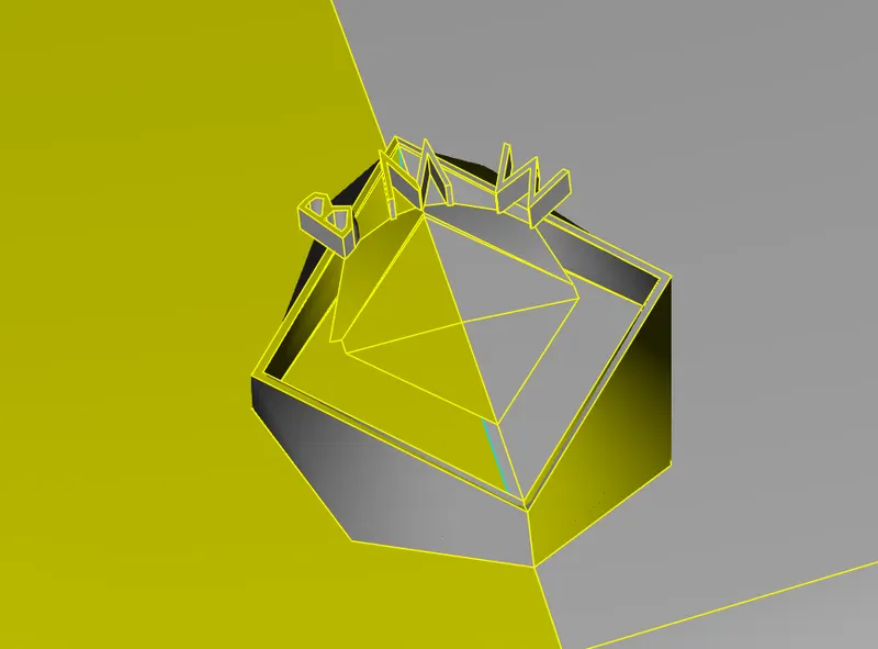
After :
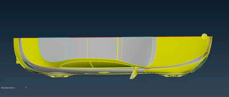
The geometry of the car is axi – symmetric in nature (except the logo). Thereby, instead of resolving all the errors across the entire geometry, we cut the geometry in half (preferably the side with less errors is retained), solve the errors on that side of the geometry and then we mirror it.
The cut – section of the geometry is as shown.
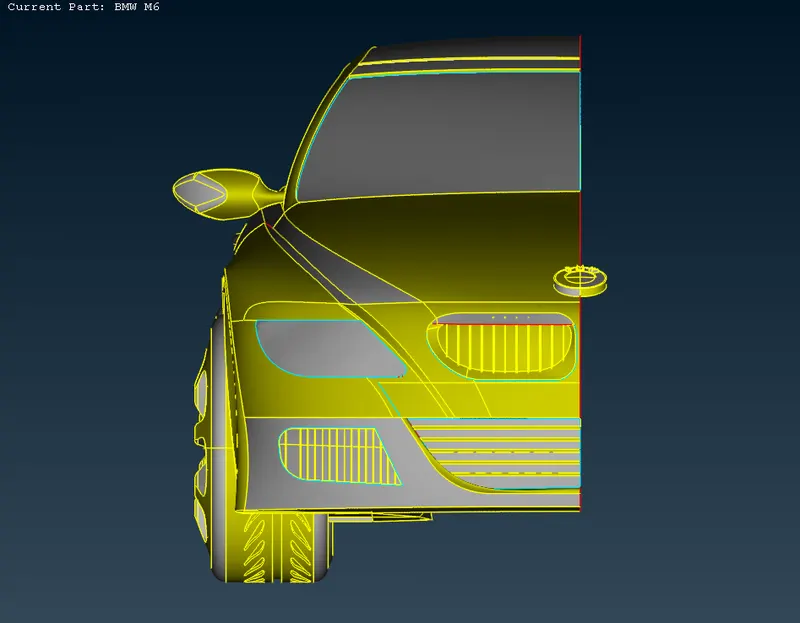
For this cut – section geometry, the various errors are as shown. We then solve this individually, part by part as follows.
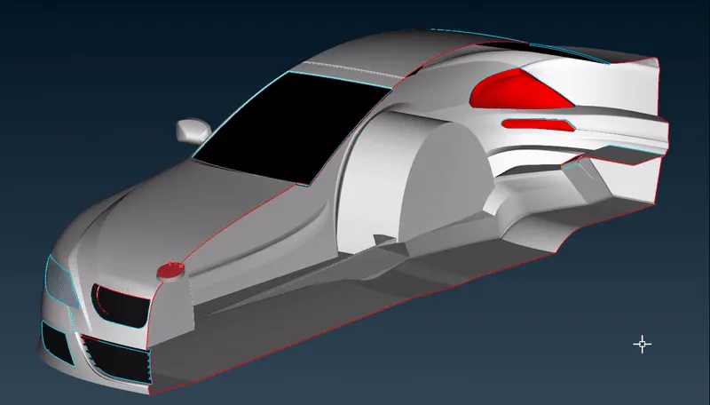
1. GRILLS
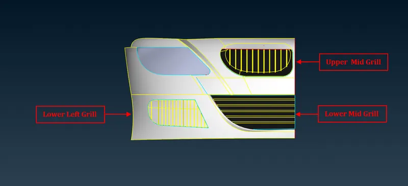
We are first going to solve the various errors in the grills of the car. We name these 3 grills as lower - mid grill, lower left grill and upper mid grill with reference to their locations and we solve them individually.
a.) Lower Mid Grill
From the below video we can observe that there are various overlapped surfaces and uneven connections in the geometry. The main objective here is to solve all these errors as well as make the entire grill as a single geometry.
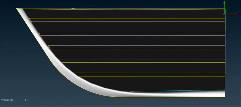
Firstly, we correct the alignment of the grills with respect to the back surface. We do this by projecting the CONS on the back surface which the grills are connected. Next, we form new surfaces with respect to the newly formed CONS as well as deleting the overlapping surfaces. Thereby, the grills are aligned to the surface as shown.
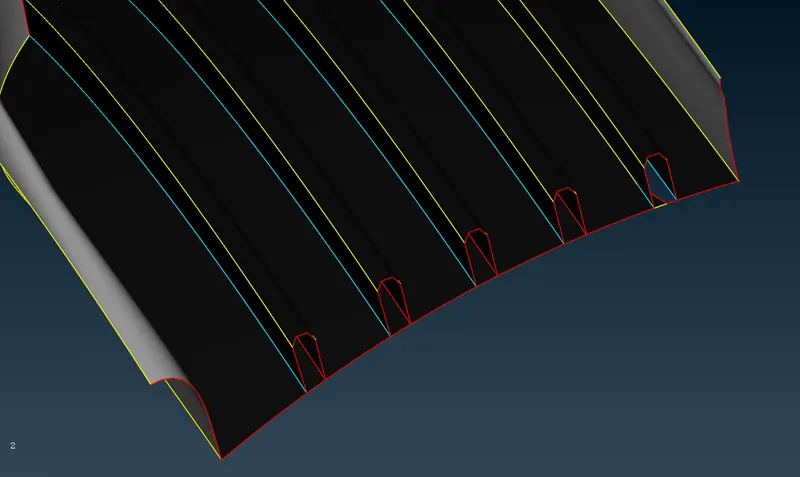
Next, we delete the extra faces on the back and side surfaces of the grill such that they are connected together as a single volume. Therefore, we obtain the final grill geometry as shown.
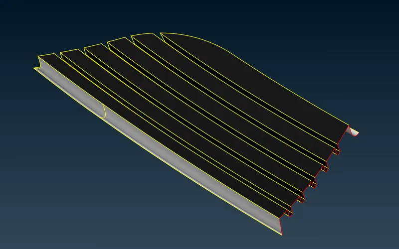
We run a local geometry check to make sure there are no errors present in the part. The single CONS on the right side of the geometry are acceptable as they are going to get connected with the mirrored part of the geometry.
b.) Lower Left Grill
By isolating the grill and observing it from different views, we can see that there are various overlapped surfaces and errors in the component, which we are going to solve one by one.
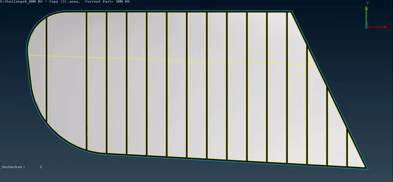
First, we delete the overlapped surfaces on the sides of the grill. The un-aligned grills at the rear end of the geometry are solved by removing a small section of the geometry at the back end and creating a new surface covering those edges and thereby, aligning them altogether.
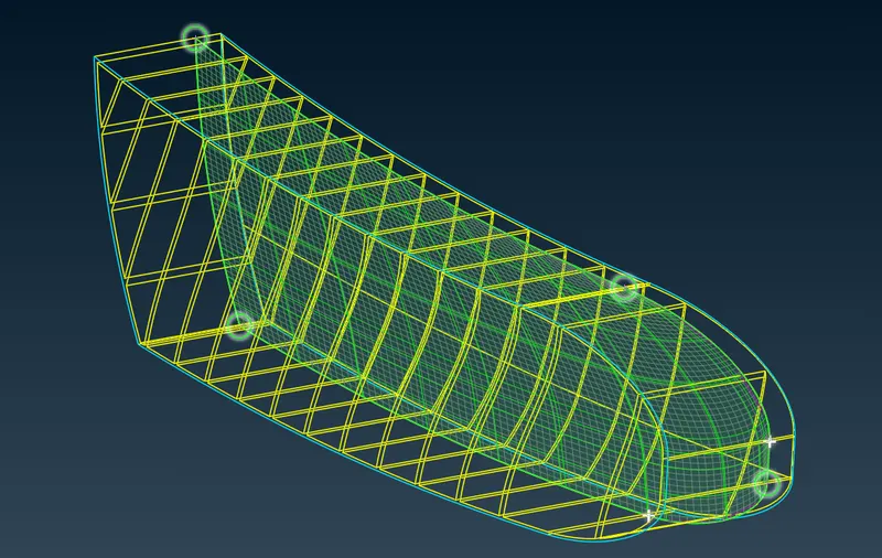
The section behind the newly formed surface is deleted and thereby, aligning the grills. Finally, we delete the intersecting surface and the extra surfaces around the grill, thereby making the geometry as a single volume and resolving all the triple CONS.
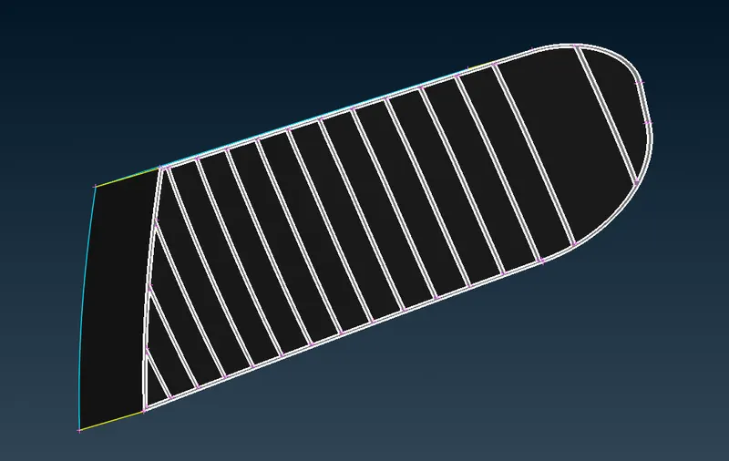
The final geometry of the grill is as shown.
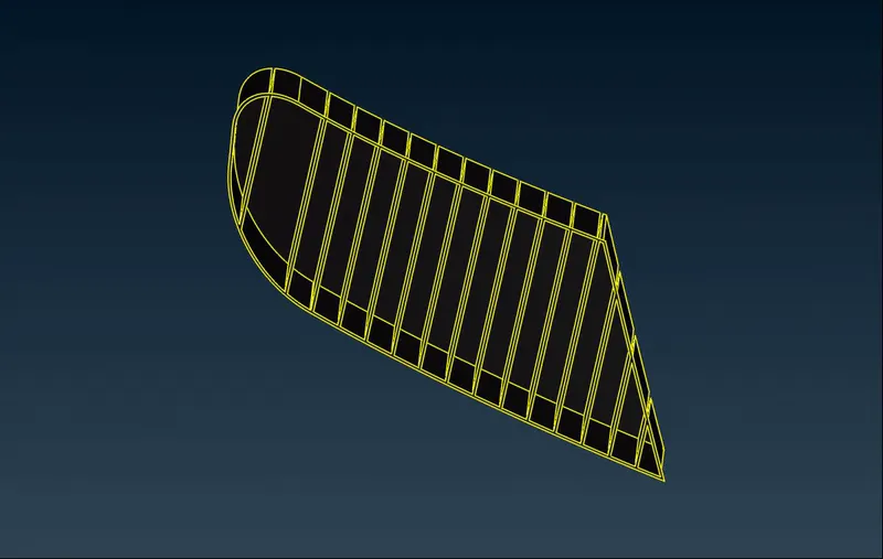
c.) Upper Mid Grill
We first isolate the grill and the surfaces connected to it, so as to visualize the errors more precisely.
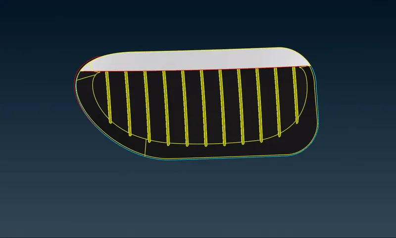
First, we delete the various extra surfaces and overlapping faces of the geometry. Further, we need to make sure that the grills are aligned altogether. In order to do so, we create small cuts along the bottom surface of the grills and we remove the extra part such that they are aligned. We repeat this for all the grills as shown.
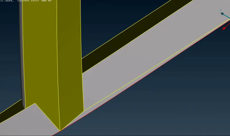
Next, we delete the back faces of the grill and create new faces in the gap inbetween the two grills, so as to make them a single volume.
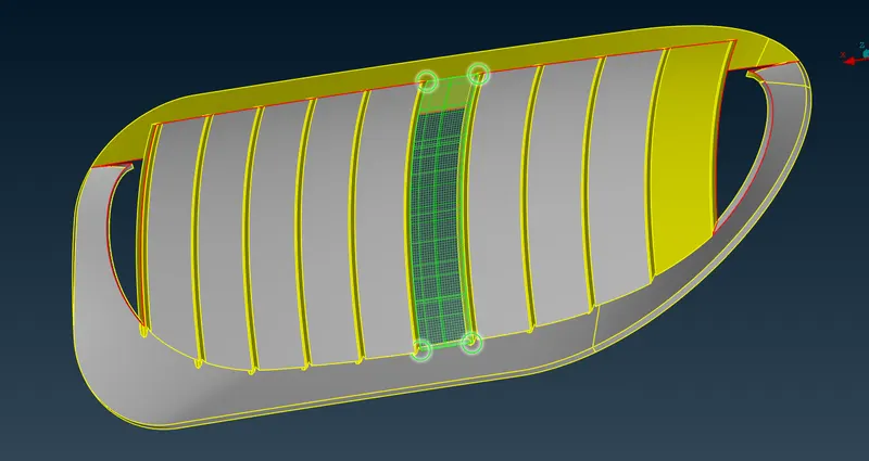
Next, we use the ‘plane cut’ option to cut the grills in alignment to the shade at the front of the geometry. This is done in order to create surfaces connecting the grills to the shade surface and thereby making it a single volume.
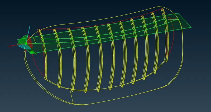
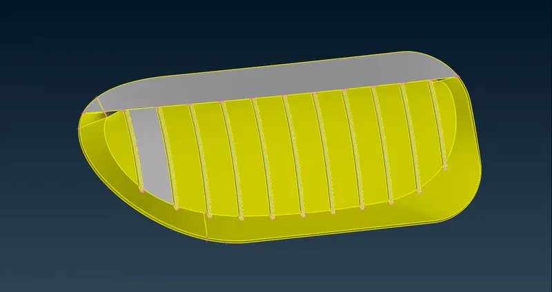
Finally, we delete the upper part of the grill and create new faces to connect all the remaining surfaces together such that we obtain our final geometry which is free of errors, as follows.
2. LOGO
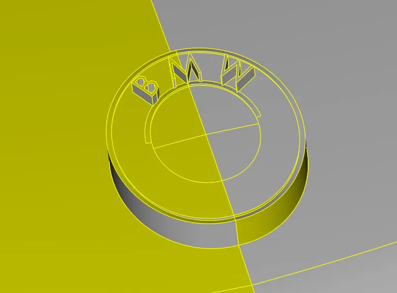
In this part, we are going clear the various errors related to the logo. We can observe that there are various overlapping surfaces.
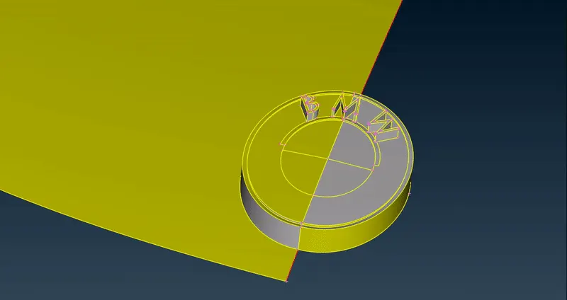
In order to solve this, we first delete the overlapping surfaces by projecting the CONS on the hood surface. Also, we delete the extra surfaces, thereby making the logo a single volume.
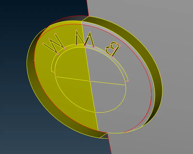
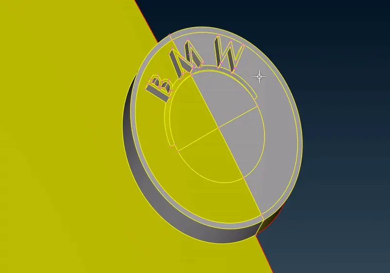
Finally, we solve the single CONS around the logo by creating new surfaces and thereby, the final geometry is obtained as follows.
3. LIGHTS
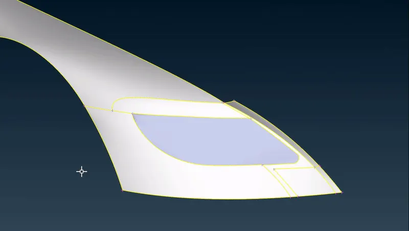
The below geometries represent the front and rear lights of the car. We can observe the various errors and overlapped surfaces, which we are going to solve one by one.
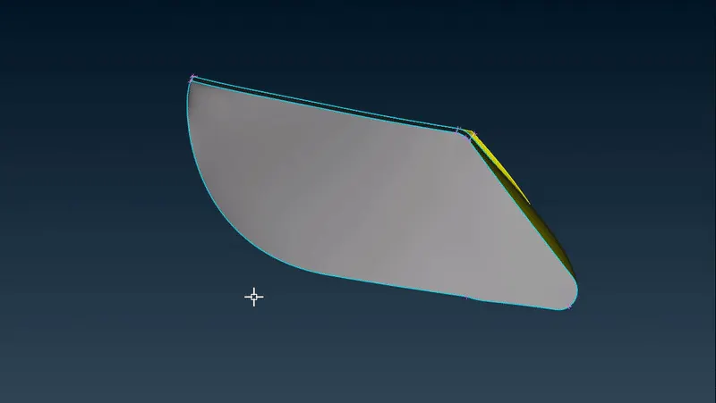
First, we are going to solve the triple CONS by deleting the overlapping surfaces as well as the additional surfaces. Thereby, the geometries are simplified as shown.
4. WINDOWS
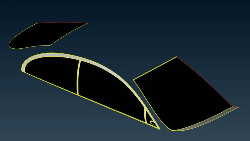
By isolating the geometry, we can observe that there are various triple CONS due to the extra edges of the geometry.
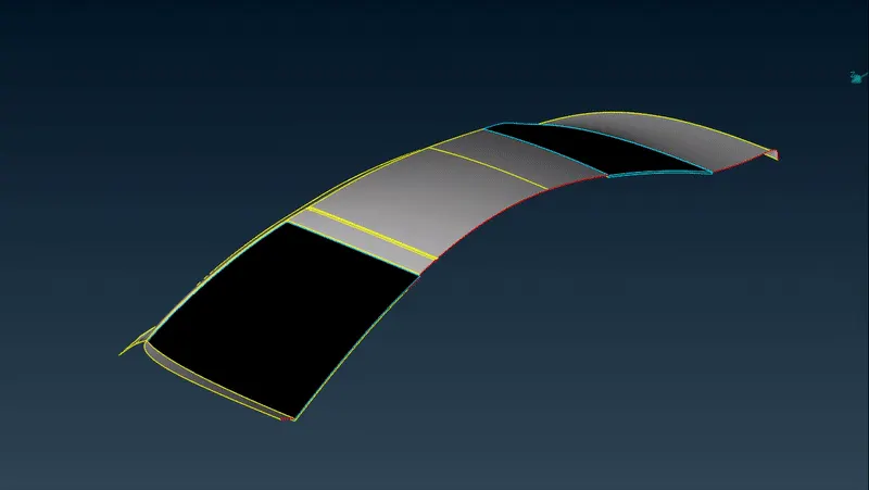
We solve these triple CONS by deleting the extra surfaces and simplifying the geometry down to single surfaces as follows.
5. OPTICAL REAR – VIEW MIRROR
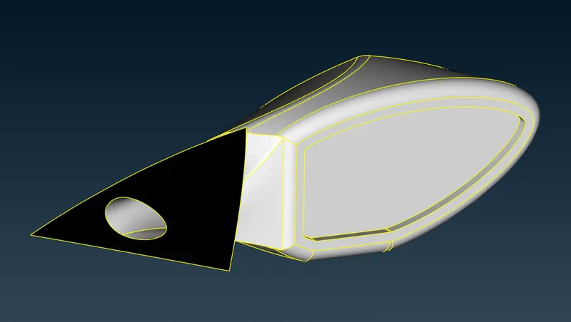
The rear-view mirror is attached to the side window and consists of triple CONS and overlapped surfaces as shown.
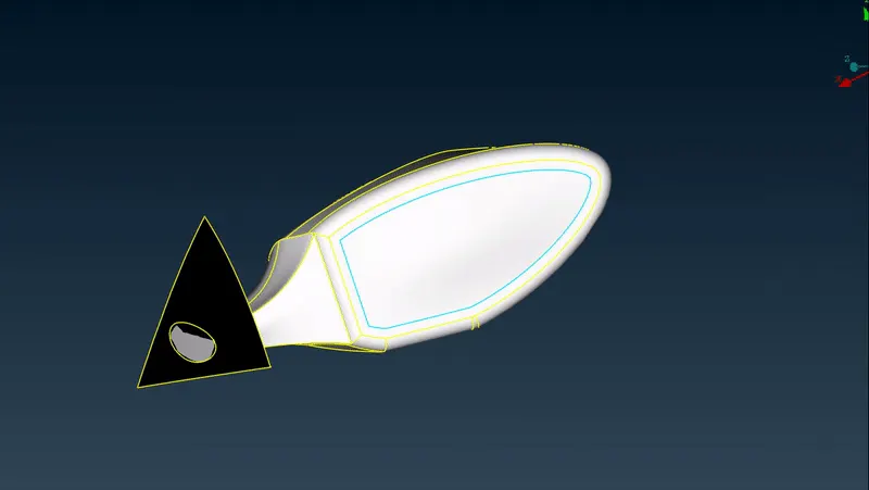
We solve the triple CONS by deleting the extra surfaces. In order to make the mirror a single volume, we remove the overlapping part from the side window. The final geometry is as shown.
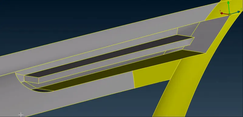
6. SIDE SKIRT
Here, we are going to perform topo cleanup on the skirt at the side of the car such that it is free of errors and is a single volume.
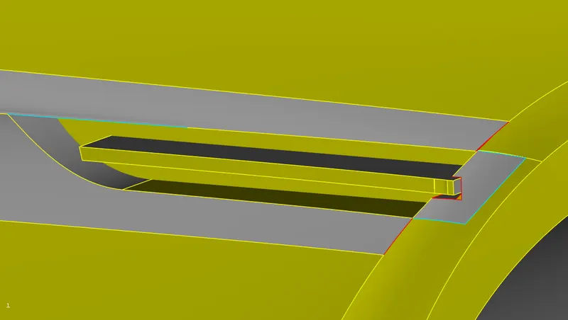
The first step is to delete the extra surfaces from the geometry. For the part of the geometry shown below, we use the ‘extend’ option to extend the bottom plane such that it intersects the geometry.
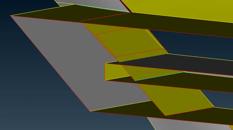
Further, we refine the geometry by cutting off the unnecessary surfaces as well as the extended surfaces. We use the ‘project cut’ option to cut off the extended surfaces and align them to each other. The final simplified geometry of the side skirt is as shown.
7. WHEELS & RIMS
This part of the geometry contains triple CONS around the surface of the rims, caused due to the overlap of surfaces. We simply resolve it by deleting those extra surfaces and forming new surfaces over the missing faces as follows.
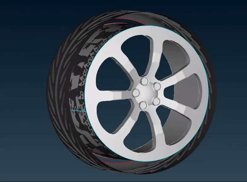
We repeat the same procedure for both the wheels.
8. CAR FLOOR
Finally, we clear out the intersecting surfaces covering the floor of the car as well as other small corrections throughout the whole geometry such as small faces and sharp edges. We use the ‘Coons2Curves’ function to create an outline for the floor before deleting it and rebuilding it again.
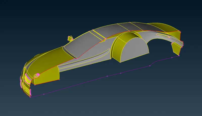
In order to solve these intersection errors, we use the ‘intersect’ option to define certain CONS on the intersecting surfaces and then we delete the unnecessary surfaces.
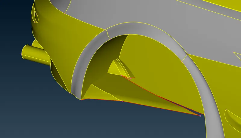
Finally, we rebuild the floor by creating new surfaces with reference to the curves and we thereby obtain the final geometry as follows.
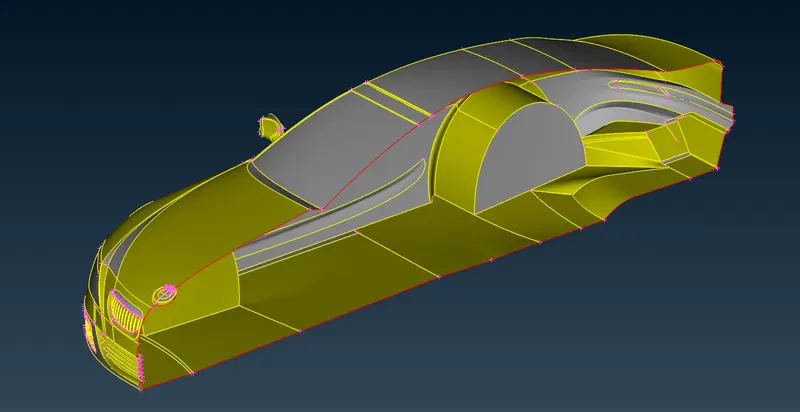
We finally run a geometry check on the entire geometry to make sure there are no errors and then we move on to naming the PID’s.
ASSIGNING PID’s :
After all the errors in the geometry have been solved, we assign PID’s to each individual component of the geometry. The assigned PID parts are as follows.
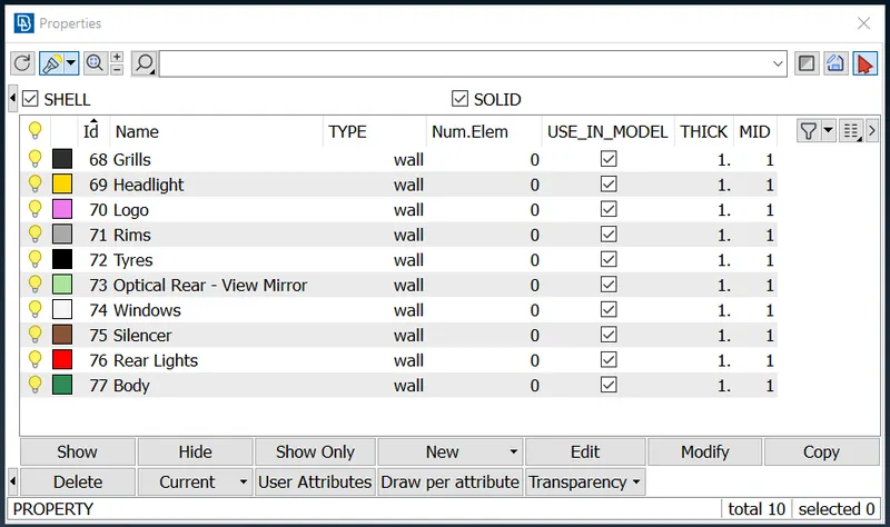
The various components of the geometry with respect to their PID’s are displayed as shown.
MESHING :
The next step in the process after assigning the PID’s is meshing the half part of the geometry. We mesh each individual component in accordance to the target lengths provided in the problem statement.
- Body - 3 mm
- Lights - 4 mm
- Grills - 1 mm
- Rims and Tyres - 2 mm
- Optical Rear-view mirror - 2 mm
- Window - 2 mm
- Silencer - 3 mm
- Logo - 1 mm
1.) Logo & Grills = 1 mm Target Length
In order to separately mesh these components, we first isolate these geometries and we provide the perimeter and macros length as 1 mm for these geometries.
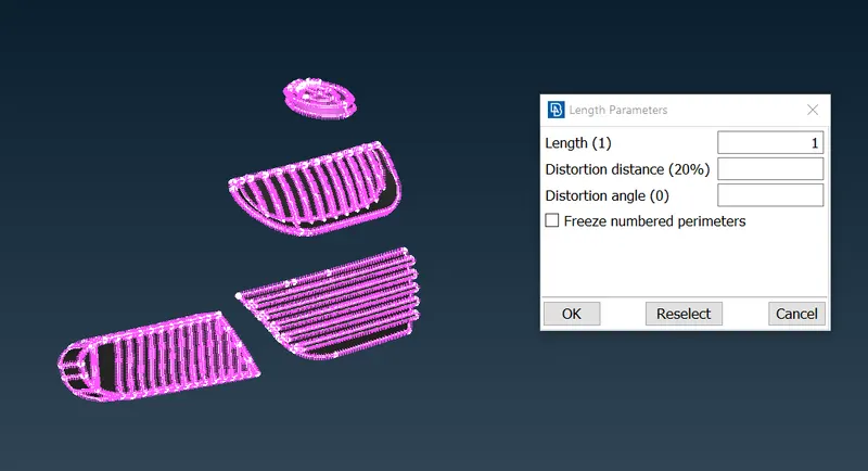
In the next step, we provide the quality criteria for meshing. We can either provide the local minimum and maximum lengths or we can provide the global lengths such that the meshing size of the entire geometry is bound within that range.
From the problem statement, we can see that the minimum target length is 1 mm and the maximum is 4 mm. In order to cover this range of element sizes, we provide the global minimum length as 0.1 mm and global maximum length as 6 mm.
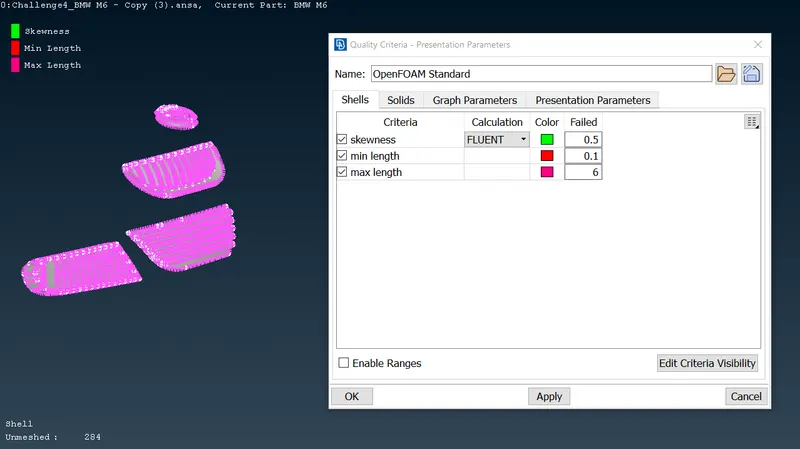
After the mesh has been generated, we obtain a total of 307 off elements in the geometry. These are the elements which do not meet the quality criteria, of which most are skewed elements.
We resolve these off elements by using the ‘improve’ function so as to reconstruct and reshape the mesh elements such that there are no more off elements.
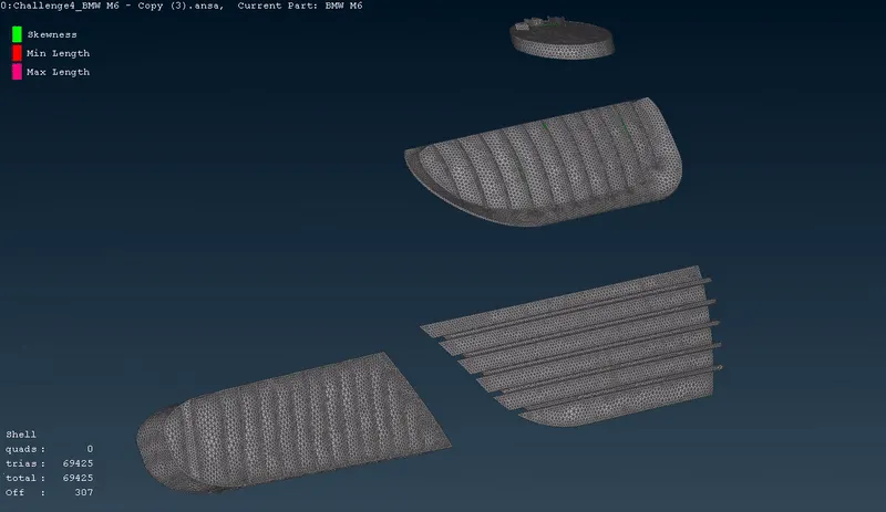
The final meshed geometry is as shown and does not contain any off elements.
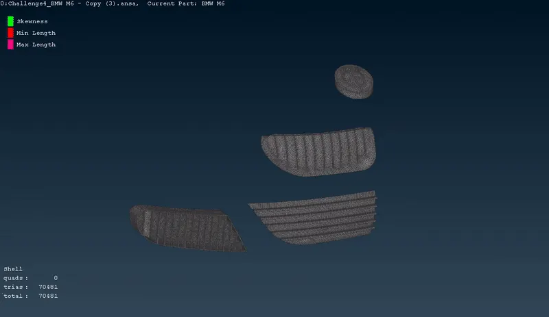
2.) Windows, Optical Rear – View Mirror, Rims & Tyres = 2 mm
Firstly, we isolate the geometries to which we are going to generate meshing of the same target length and then we provide the perimeter and macros length as 2 mm.
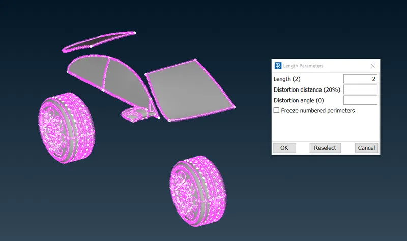
With reference to the global quality criteria provided for the minimum and maximum lengths, we generate CFD meshing for these geometries as shown.
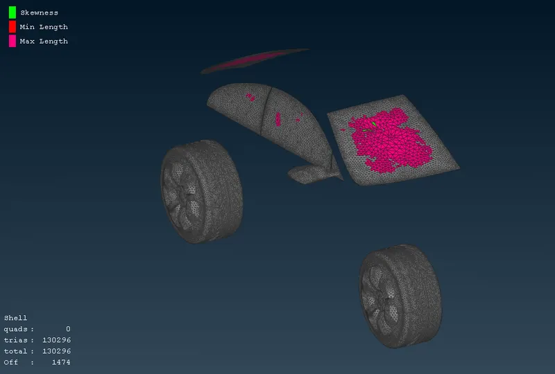
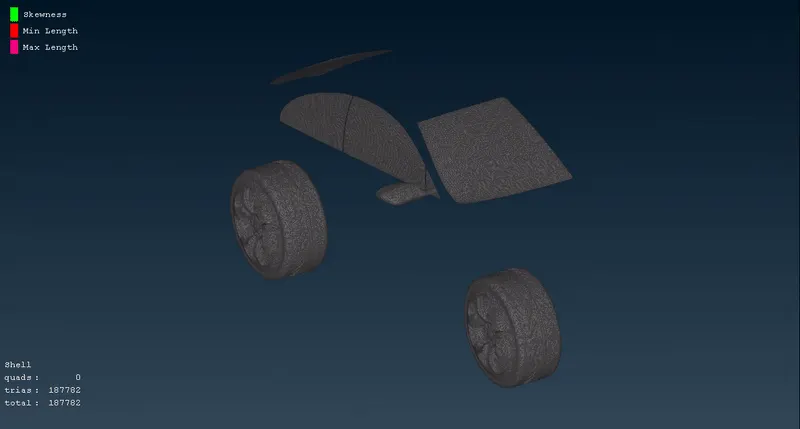
In order to solve these off elements, we use the reconstruct and reshape functions and thereby getting rid of the off elements errors and obtaining our final mesh as follows.
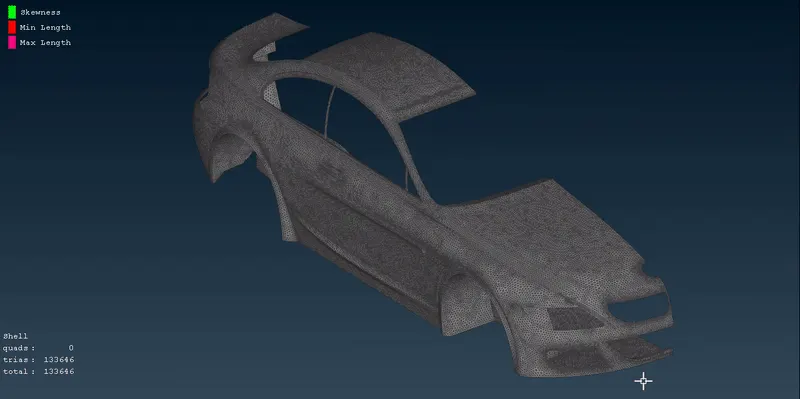
3.) Body & Silencer = 3 mm
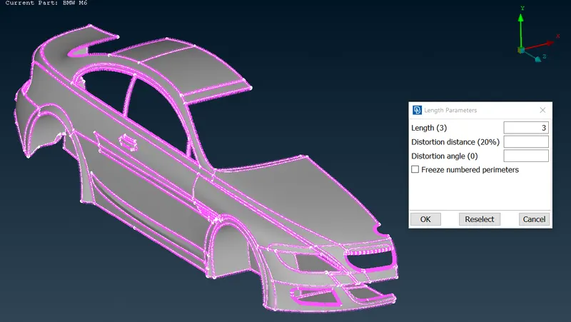
By isolating these parts, we provide the perimeters and macros lengths as 3 mm for the geometries.
We generate CFD meshing for these geometries.
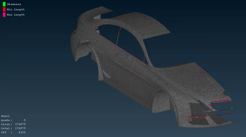
The off elements are solved by reconstructing and reshaping the elements and our final meshed geometry is as shown below.
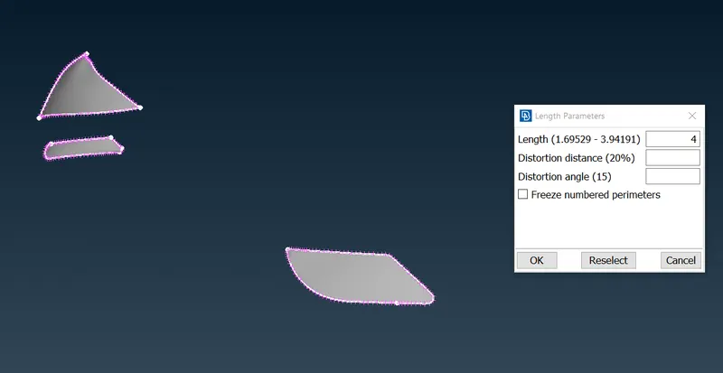
4.) Lights = 4 mm
Firstly, we isolate the headlight and rear light geometries and we provide the macros length as 4 mm.
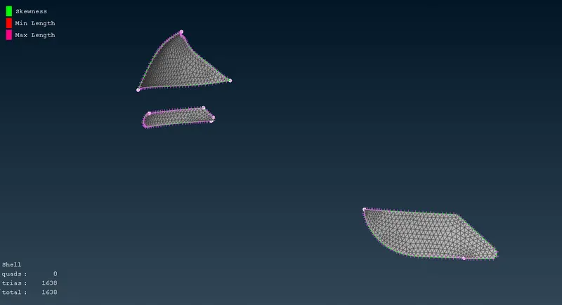
Finally, we generate CFD meshing for these surfaces as shown. No off elements are generated for these surfaces.
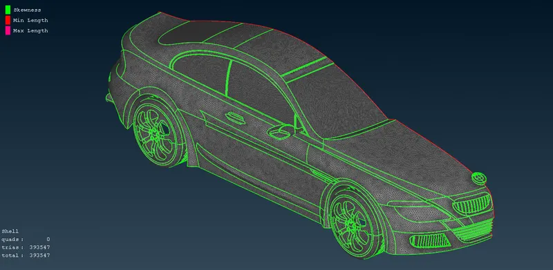
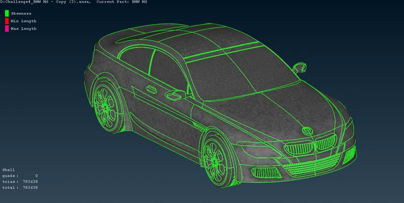
Thereby, the entire car geometry is meshed in accordance to their respective target lengths. We can observe that there are no off elements in the geometry and thereby, we can move further.
MIRRORING :
After obtaining the mesh for the half part of the geometry and clearing all the off elements as well, we then move on to mirroring that part of the geometry so as to obtain the entire geometry.
As the logo is not symmetric, we mirror all the other surfaces except the logo by using the ‘transform – copy’ option. We use the ‘symmetry 3 points plane’ option to select three random hot - points along the cut section of the geometry. The final mirrored geometry is obtained as follows.
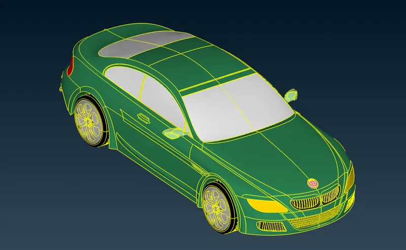
Along with the geometry, the meshing is mirrored as well.
WIND TUNNEL CREATION :
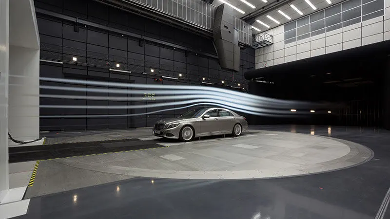
Wind tunnel tests help us better understand the nature of flow of air over and around a vehicle or object, as well as the effects it causes on that object, especially aerodynamic forces. The characteristics of the flow around the object can also be visualized using a number of techniques — smoke injection and oil flow on the test article to name a few — meant to “make the invisible air visible”. Also, the aerodynamic forces acting on the object, such as drag and lift, can be measured by accurate load measuring devices.
After the entire geometry has been meshed, mirrored and the off elements brought down to zero, we then move further to create a wind tunnel geometry around the car. We create a domain around the car with reference to the following dimensions.
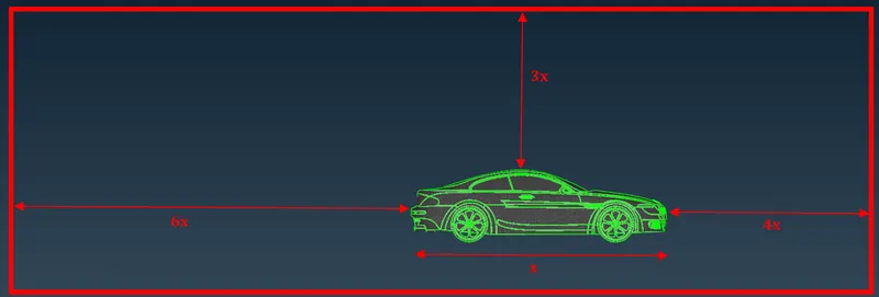
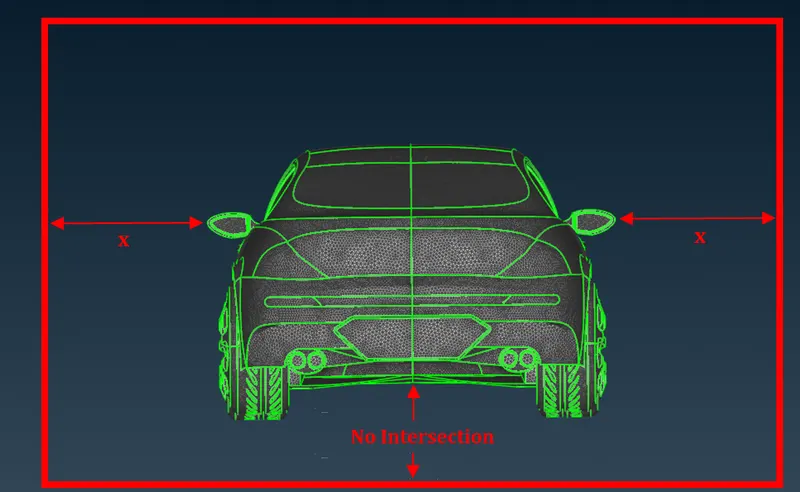
With reference to these dimensions, we first create the bottom surface of the wind tunnel by creating nodes at their respective distances as shown above. We first project a point 200 mm below the mid - point of the car and then we create the corner nodes with this node as the reference point.
Here, x is the total length of the car and is approximately equal to 1300 mm.
x = 1300 mm
The nodes created for the creation of the bottom face are as follows.
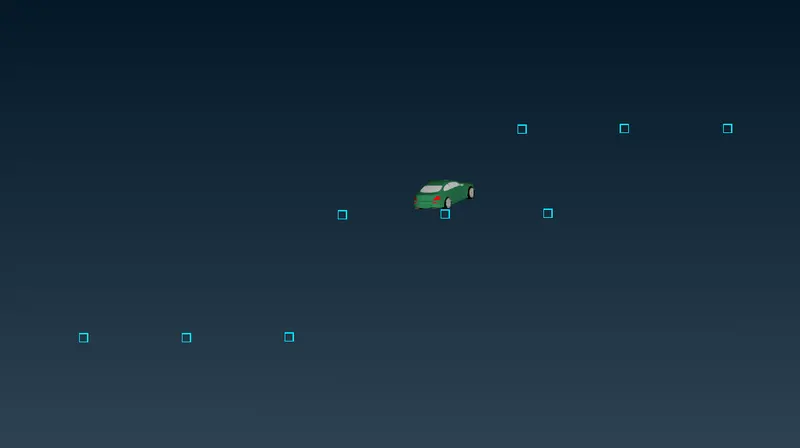
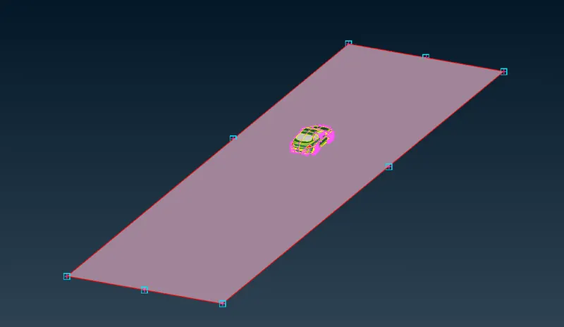
Now, we use the create new curves connecting the nodes and we thereby create the bottom face and assign the respective PID to it.
Now, with reference to our bottom face, we project the nodes so as to create our top surface as well.
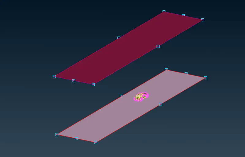
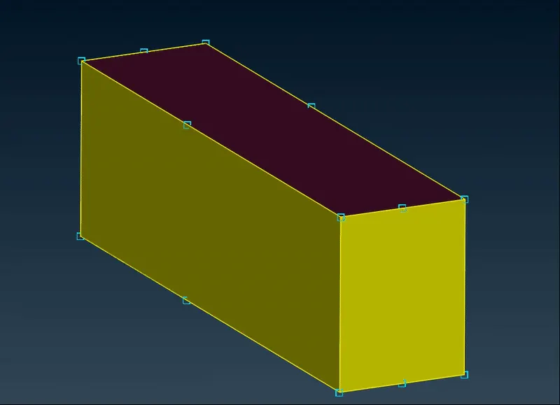
We create new side faces so as to enclose our car geometry inside it and thereby obtaining our wind tunnel geometry.
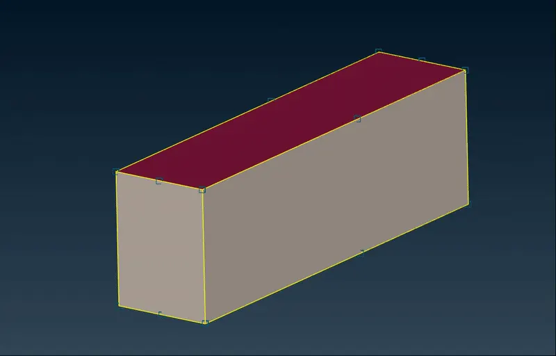
WIND TUNNEL MESHING :
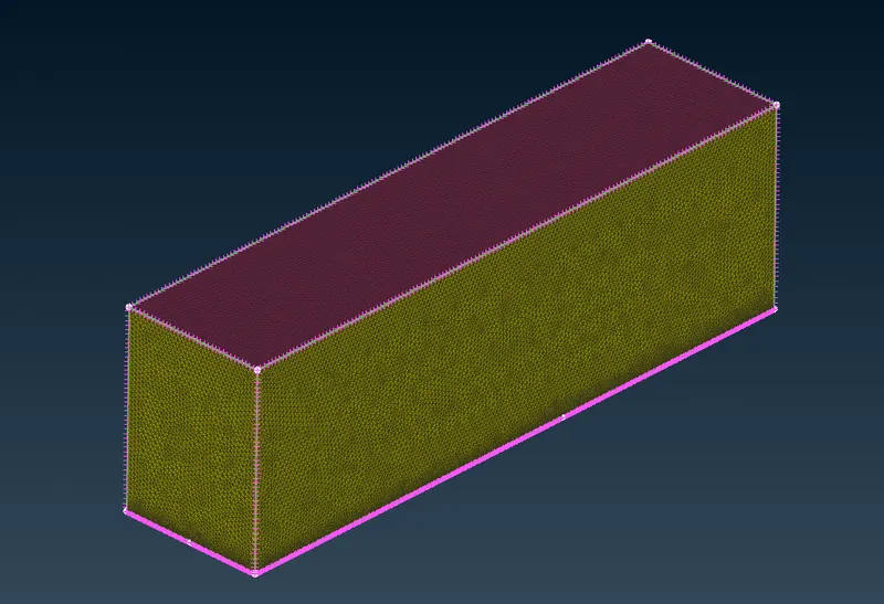
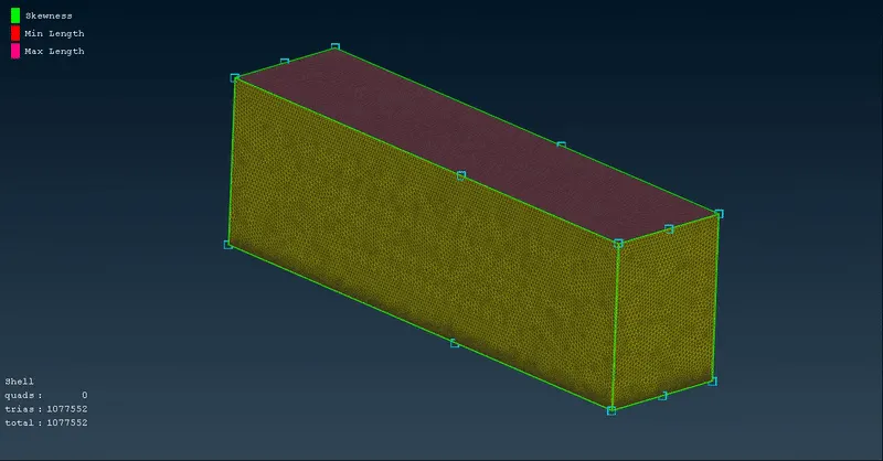
Finally, we are going to generate meshing for all the faces of the wind tunnel geometry. First, we are going to generate tria meshing of element size 20 mm for the bottom face.
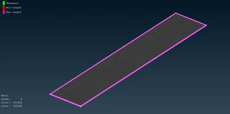
Similarly, for the top face, we generate meshing of an element size of 100 mm.
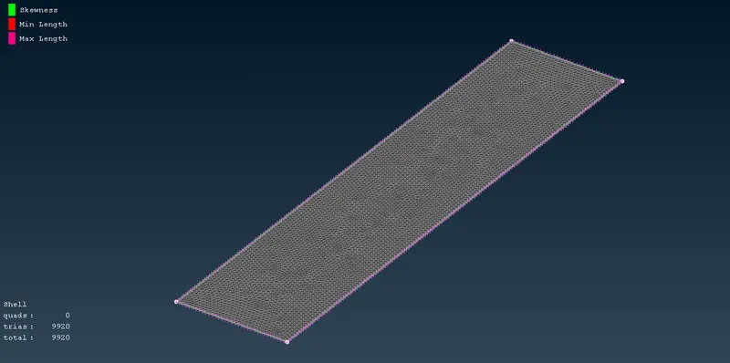
For the side faces, we generate a growing mesh, growing upward from the bottom face up to the top face. The element size starts from 20 mm and grows to a size of 100 mm as it moves upward.
We generate the growing mesh by using the manual spacing option, with the start point being 20 mm and end point being 100 mm.
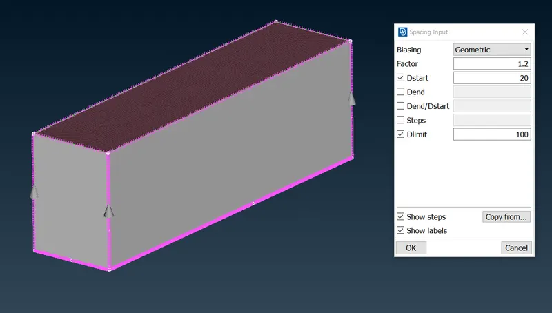
Thereby, the final wind tunnel geometry is obtained as follows.
`360^o` View of Final Geometry :
- Meshed View
- Geometrical View
Final Geometry File : https://drive.google.com/file/d/1vhOs8zwEberwhmksdmKRh0PiDfjP866y/view?usp=share_link
CONCLUSIONS :
The topology clean-up has been successfully carried out on the BMW car geometry and all the geometrical errors have been successfully solved. Surface meshing of various target lengths has been generated for the different components of the car. It can also be observed that there are no off elements, thereby clearing the quality criteria.
Finally, a wind tunnel geometry has been created around the car and surface meshing has been generated for the same as well.