Week 4 Challenge : CFD Meshing for BMW car
Aim:-Aim of this project CFD Meshing of given BMW car model in ANSA.
Objective:-
1) Mesh diffrent parts of car model with different target length
- Grils and logo parts have target length 1mm.
- Rims, tyres, rear view mirror, and window parts have target length 2mm.
- Silencer and body have target length 3mm
- And lights target length is 4 mm
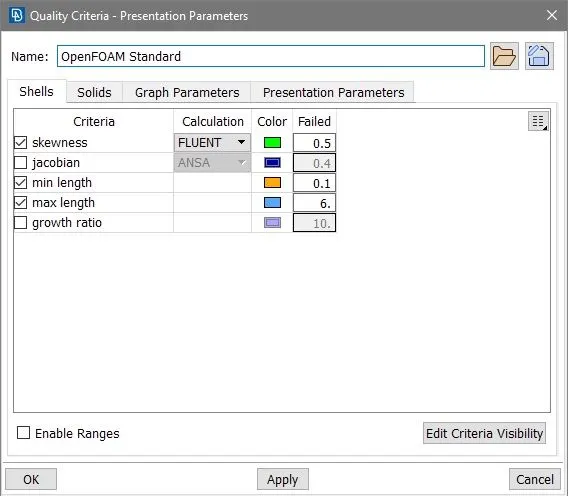
2) Quality checks of meshing with 2D Trias element having skewness 0.5, minimum and maximum length 0.1 and 6 mm respectivly. Modifying mesh such that there is no off element remain in all gometry.
3) Creating wind tunnnel such a way it's volume meshing with tetra element may takes upto 2 days of time.
Procedure:-
1) Geometry clean up
First import model and you can se some features in model are not much accurate because of resolution, then go to Tool's>Setting>Resulution/Tolerance/Units>Perimeter length and set length to 1.
Now here aim of meshing is to perform wind tunnel analysis, therefore only external surface or volume are needed so we have to remove internal parts and thickness in our model. Now here we also consider that our geometry is axis symmetry so we delete all R.H.S surfaces and work on remaining L.H.S. surfaces. Note that only logo is not axis symmetry so we can delete logo half part, keep ful part of logo.
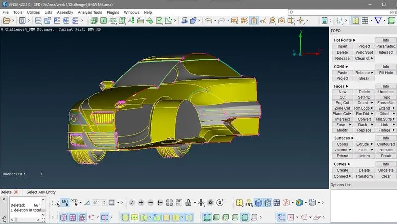
Here in above image you can see single and triple conns in gometry. Now clear this gometry one by one.
I) Grill :- Now isolate this grils part as shown in below image, here you see there are some single and triple cons are there. This ois is because of we delete R.H.S. part of gril and there is thickness of each grils.
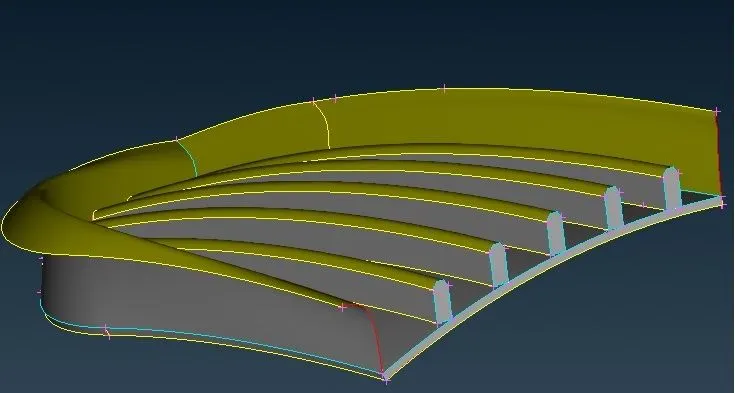
At the end grils should look like the below image
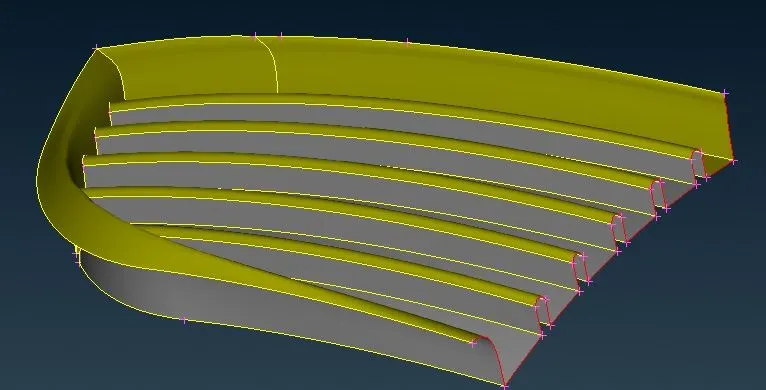
First remove the thickness by deleting each unnecessary faces then you can se triple cons are gone and only double cons are there and you can see two red cons at this moment is ignore it because at the end i mirrior my geometry.
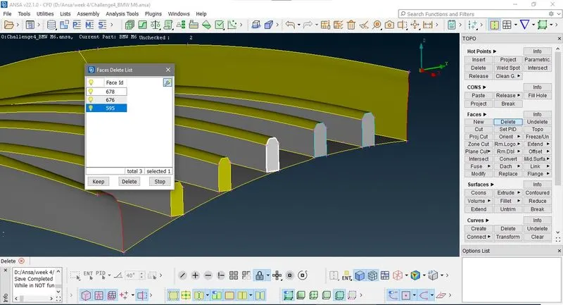
In above image you can see as all tripe cons gone but still grills are making saperate volume because grils are not aline to the cones, so we have to delete inside faces to make a single voume. for this go to TOPO > CONS > Project select bottom double cons of each grill and press mouse scrole button and select the face as shown in below image.
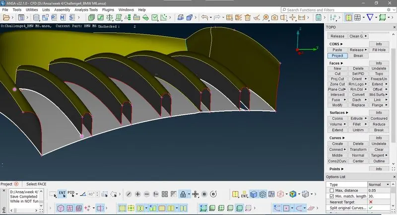
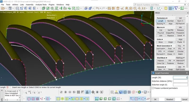
Now these project cons are not smooth curves because of bed redulution, for these smooth curve we have to go classical mesh > perimeter >length select perimeter then select curves and give length to 1 mm.
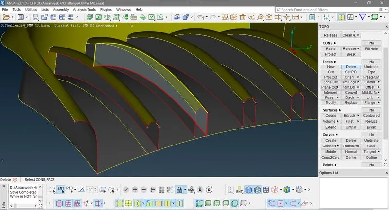
Now come back here side face in not proper mating so delete it carefully dont delete other faces.
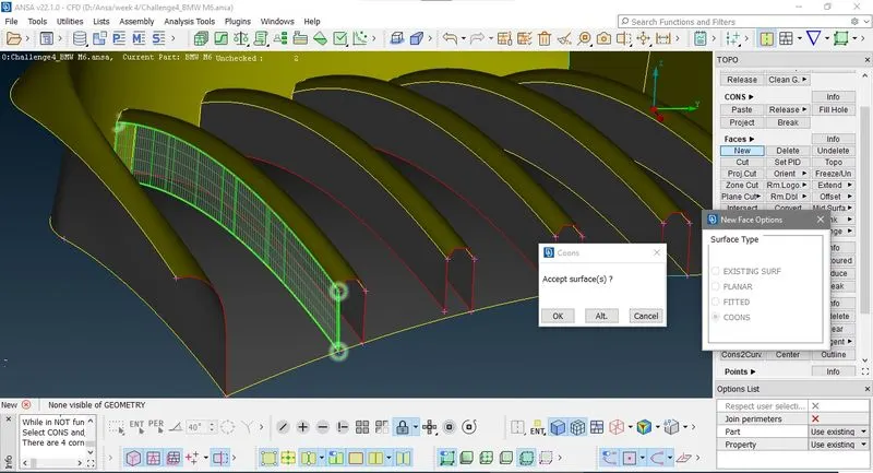
Now use coons option to recreate it. so go to TOPO>Faces>New>Coons
Now come to back side you see grill face is intersecting to outer face to make a volume you have to delete it but if you try to delete it can't delete sepratly it take entire face. so we have to isolate only this area of this face. so we go to TOPO>CONS>Project select boundary of grils and project it on surface. now you can delete this face.
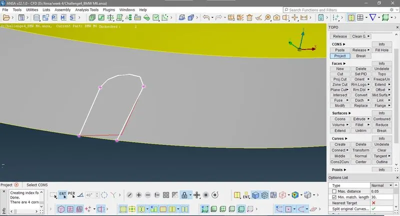
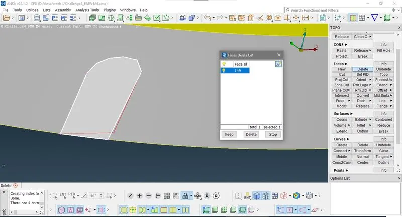
Repete this process for other the grills. At last gril you see there is small face is there use project cons for isolating it and then delete it.
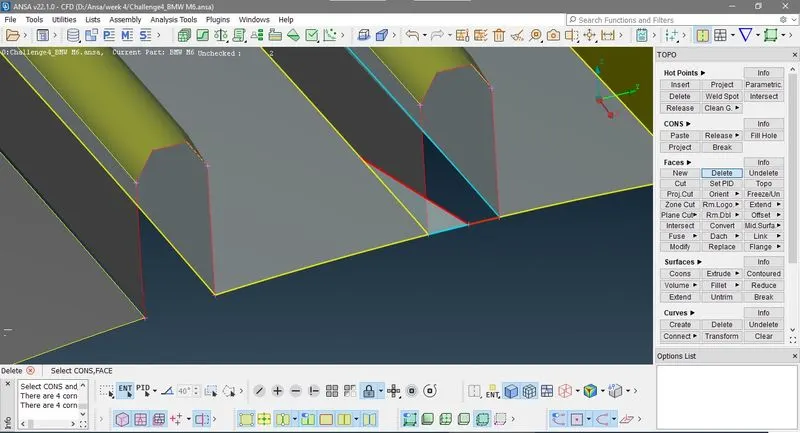
and delete all the unnecessary hot points and face then finaly you get.
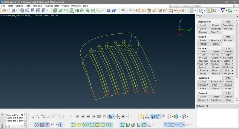
Now here you observe in wireframe mode there is a triple cons is there. This is because of an intenal face of body so hide outer face and delete the unwanted face.
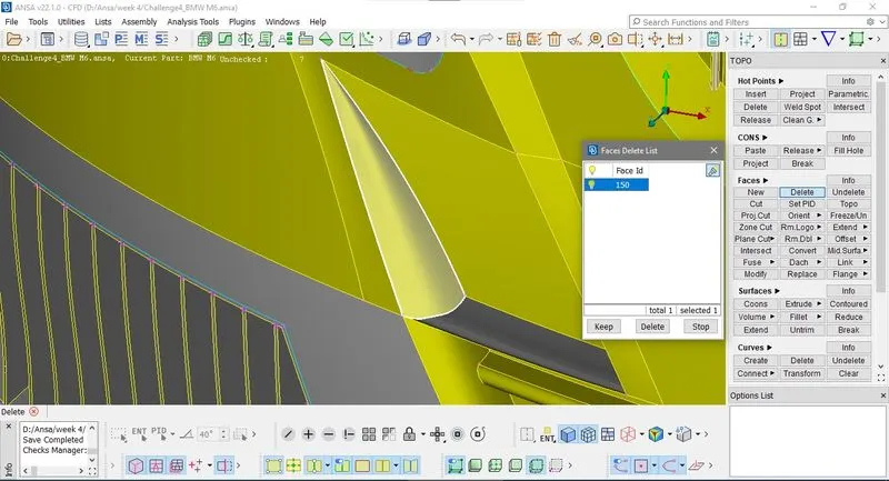
Now come to next grills, in below image you can easily observe last face of grils is not a single face and when you try to make volume there are small-small faces are there which may cause skewness in meshing.
First i create hot points by using parameter then, i use project cut to creating double cons and separating grils parts.
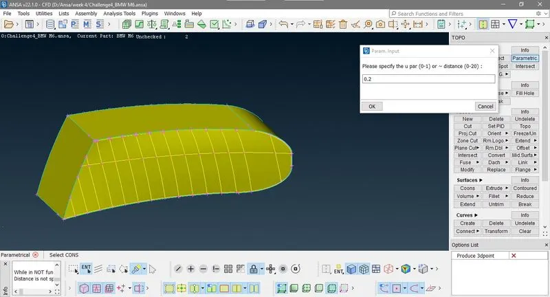
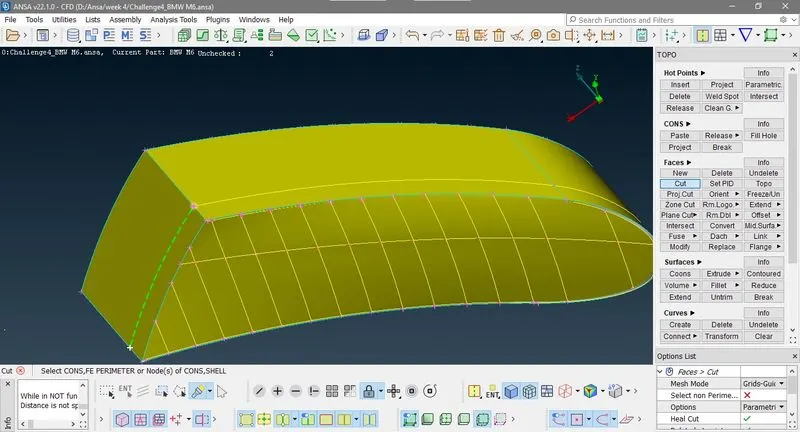
Now first create a new face by coons option, then go to TOPO>Faces>intersection first select the new created face and then select complete grill.
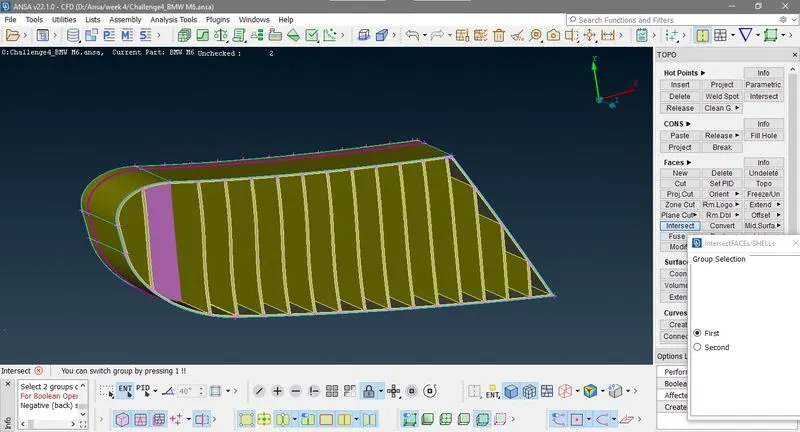
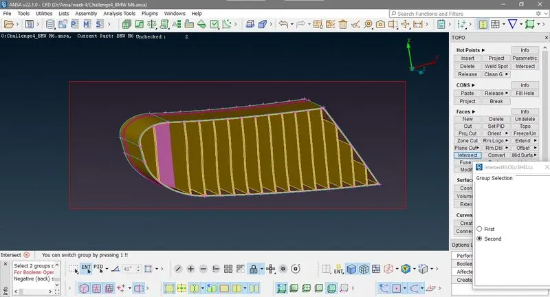
Then keep those features is require and delete unnesccery features.
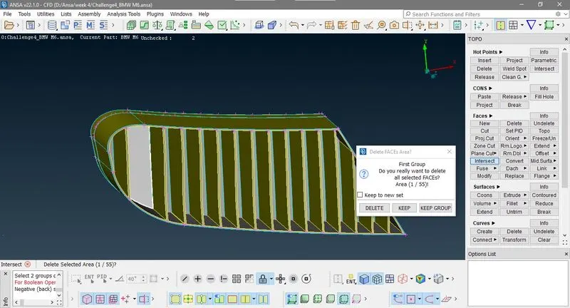
Now come to nlast grill part , in below image you can see unnecessary faces delete those.
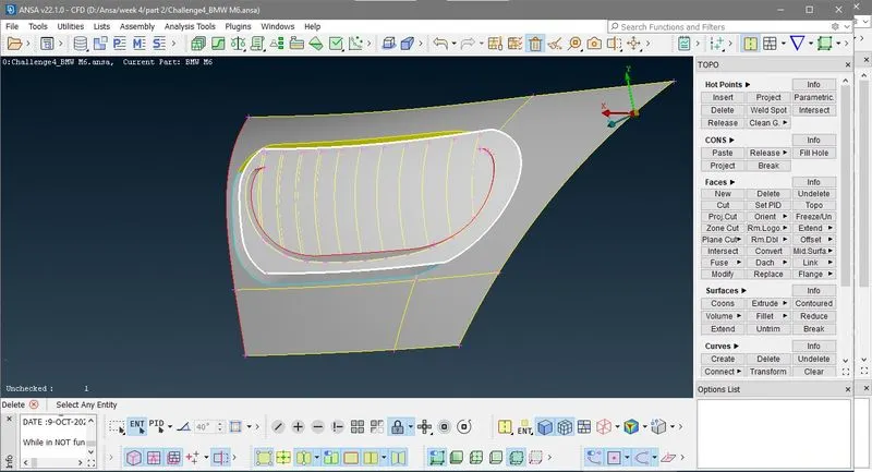
Now turn to inside you can observe grils are not aline use cut option in TOPO>FACES> cuts to isoates unnecessary face area then delete it.
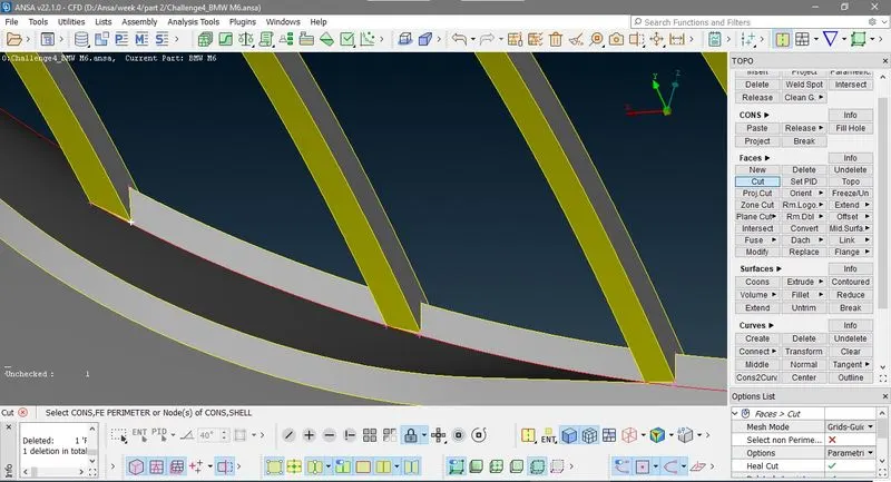
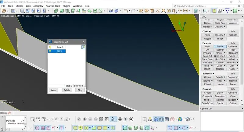
Now in below image there is red con on face so here you can't perforame cut option so first hit the top (i.e. Topological optimizer) here to convert red cons to double cons.
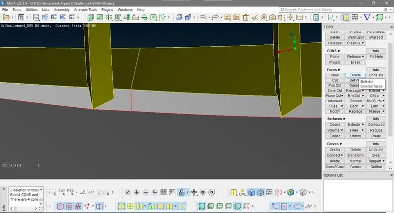
Now here in below image you can see grills end not at same palne of mating front face, so we goto to Plane cut option here go to TOPO>Faces>Planecut
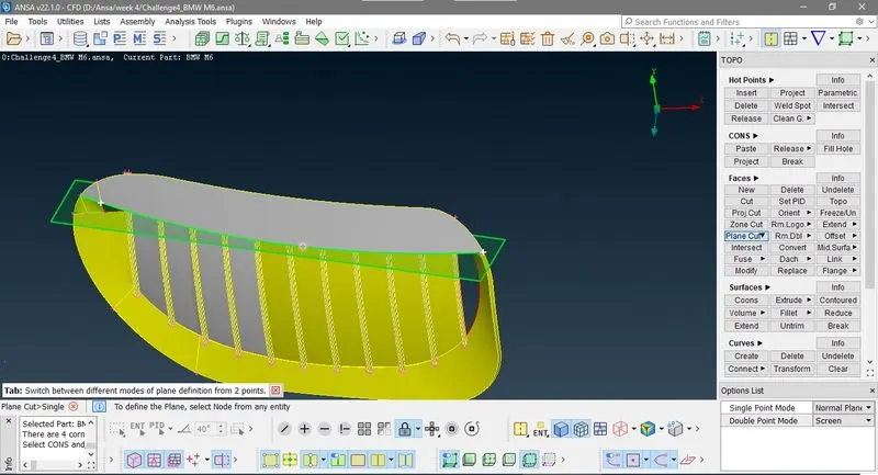
Here Ansa create and temporary plane pasing through 3 points.then delete cut parts.
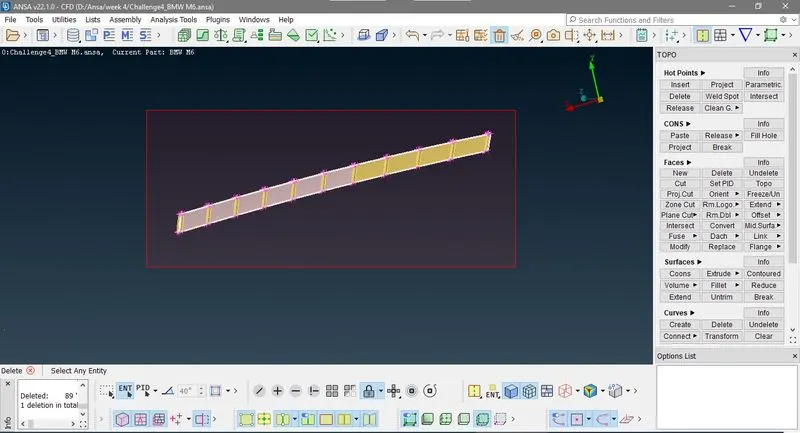
at thr end my gril looks like this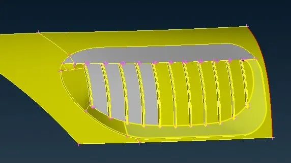
II) Logo :- Now hide all and isolate only logo part, if you see below image logo creates intenal volume so we have to cleanup logo in such a way it make a singel volume to car inside volume.
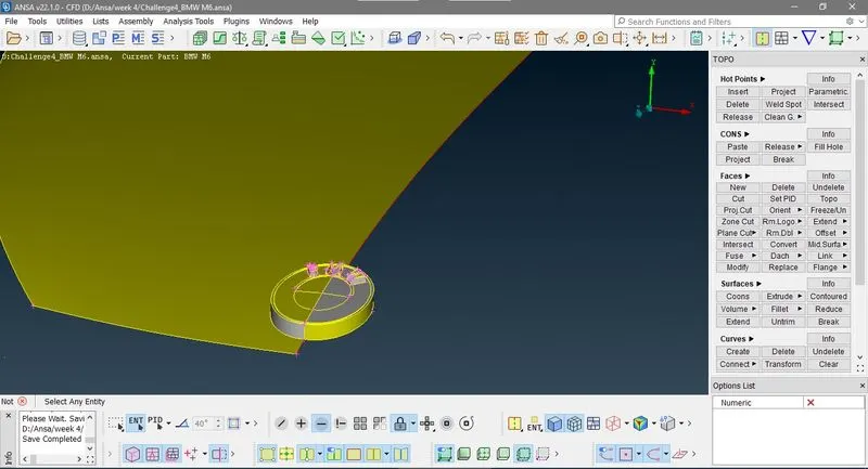
use cons project
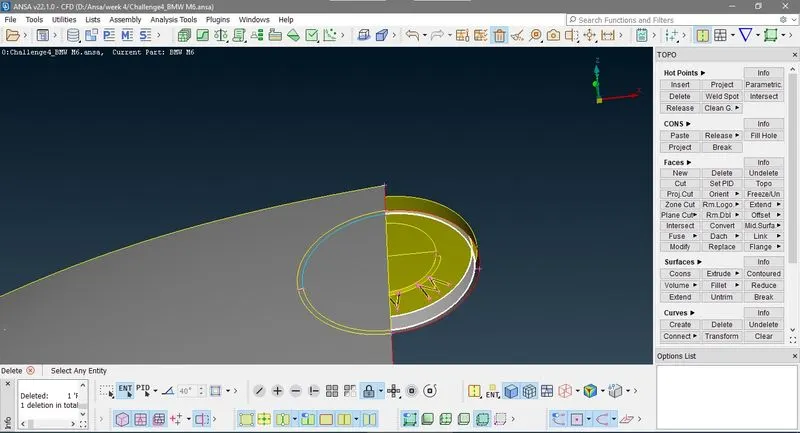
Deleting small face because these small face cause skewness in meshing.
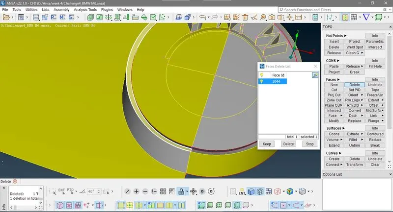
now in logo M top is producing sharp edges so delete it then crate a new face with planer option
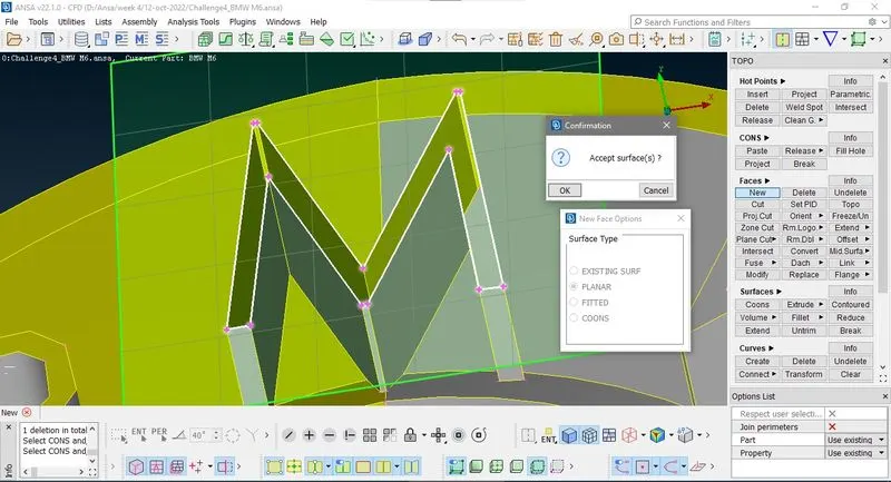
III) Head light :- Delete all the internal feature of front an rear head lights so triple cones are eleminating from the gerometry. Here in below image you can se triple cons in head light so first hide face and delete internal features.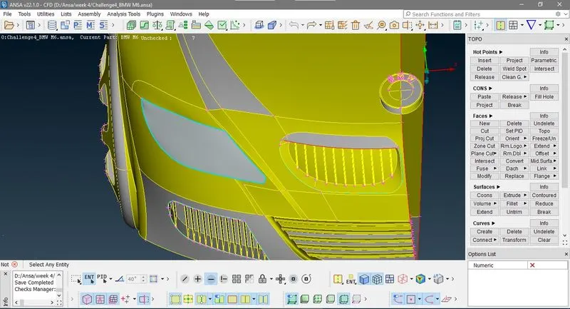
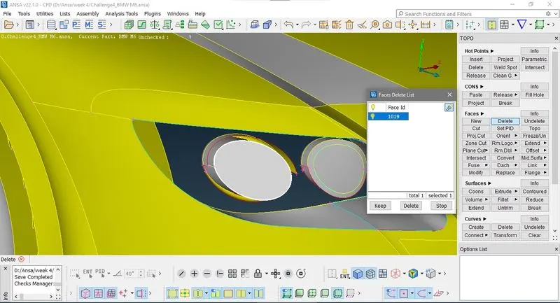
Now after deleting all internal feature you can see red cons as shown in below image delete this face and creates new by cons option
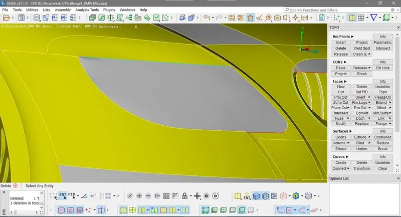
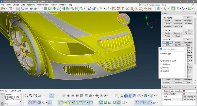
IV) Window glass :- Now we don't need the thickness in window so clear it by deleting the unnecessary faces.
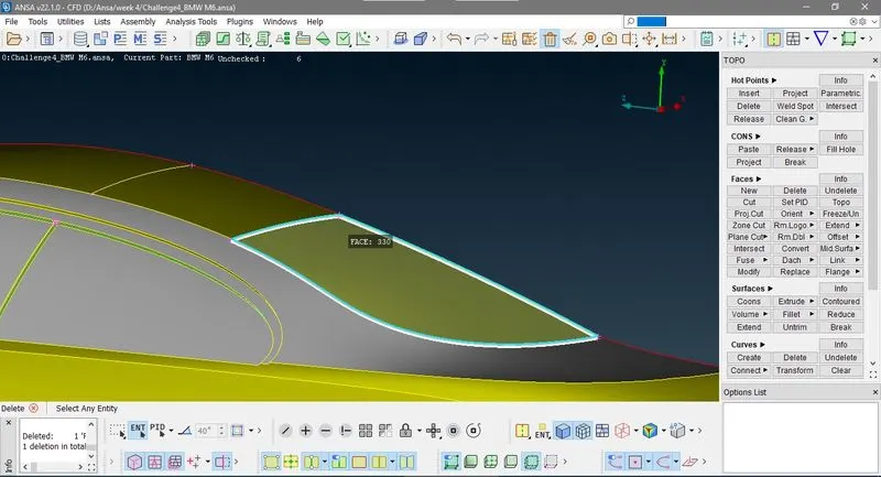
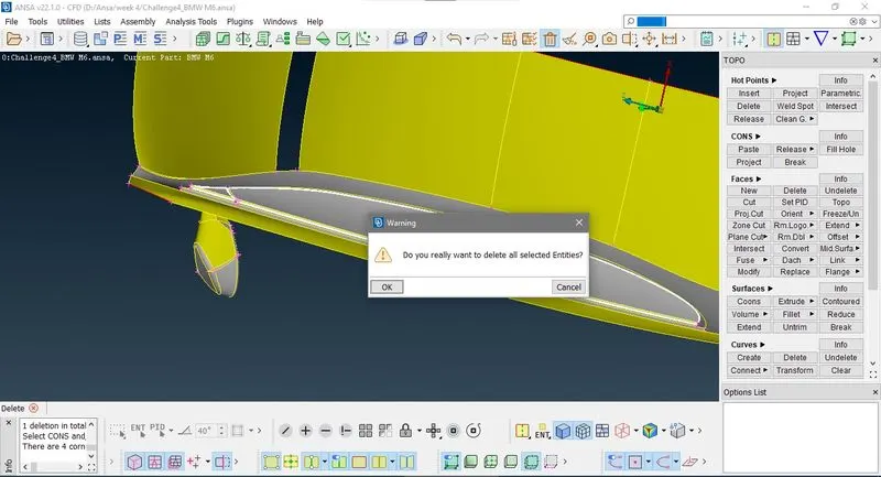
Note:- In the above image i lose the desire face while deleting so can get it back by undelete option. After it we have red cons so you have to hit Topo to resolve it.
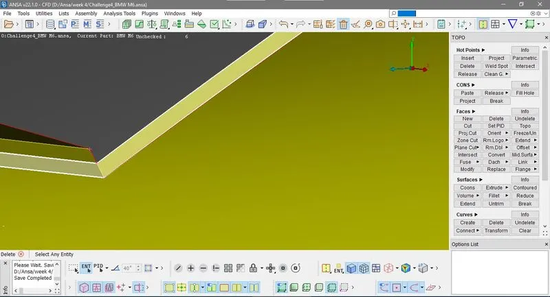
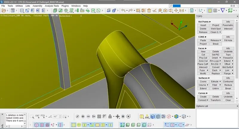
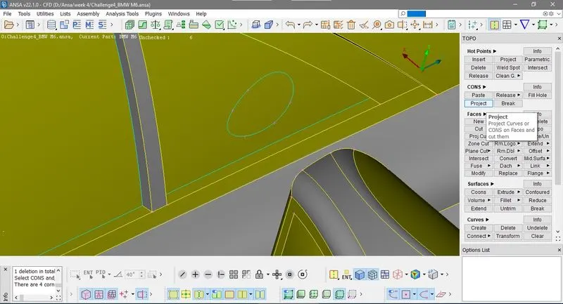
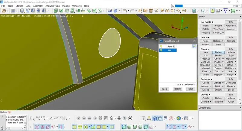
V) Rear viw mirror :- Now mirror part is not connect with car volume so we have to make cut on glass face by project cons option
TOPO > CONS> project select cons and select glass face then delete isolated face.
VI) Body :- Now go to Check manager > Geometry check > Execute
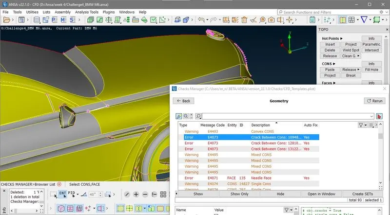
Crack betwwen cons error is because when you make a face with only few cons then some cones are not mating to the face the are not change fron single con to double con those cone called crack cons. for resolvinh it go to TOPO>CONES>PASTE first click on red con then press mouse scrole button then againg select that con. then your error esolved.
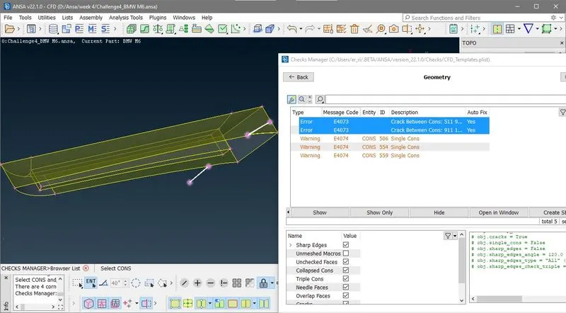
If you go to check intersection and penitration error you will find error in body flooring
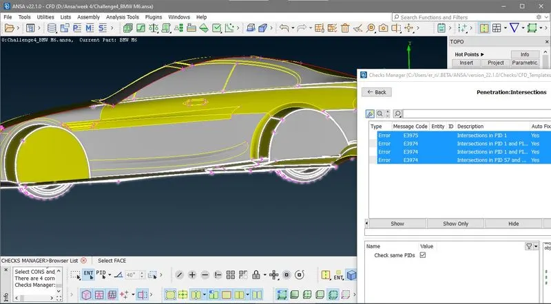
For resolving intersection error on flooring you have to delete unnecesary face on floor but if you delete those face you cant get those back at end because there no cons at free end of face. so we go to TOPO>Cons2Curv> and then select free end cons of face as shoen in image below
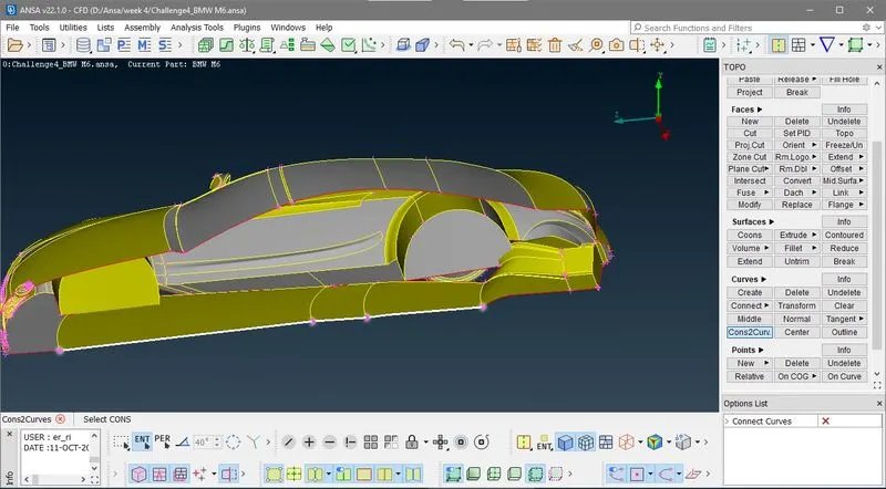
Then delet faces and creates new face acording to you requriment.
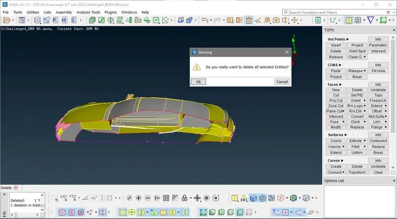
and also solve those intersection error with tyre and rims
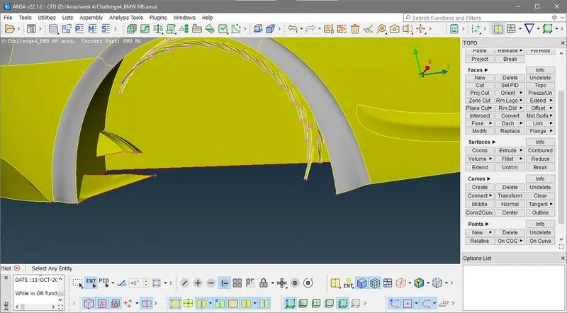
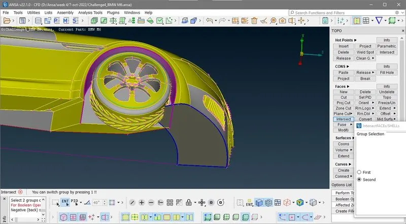
here in above image use intersection onption to seperate those intersecting face of floor to body then you get triple cone at intersection point so then isolate complet unnecesary face by using cut option.and then delete it.
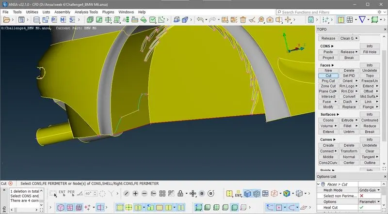
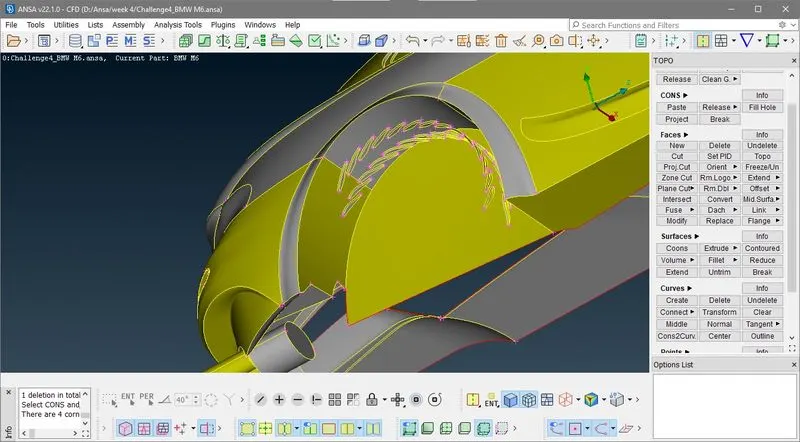
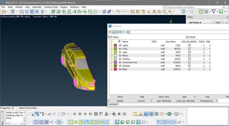
2) Assigning PID's
Befor meshing we have to create and assine PID'S.
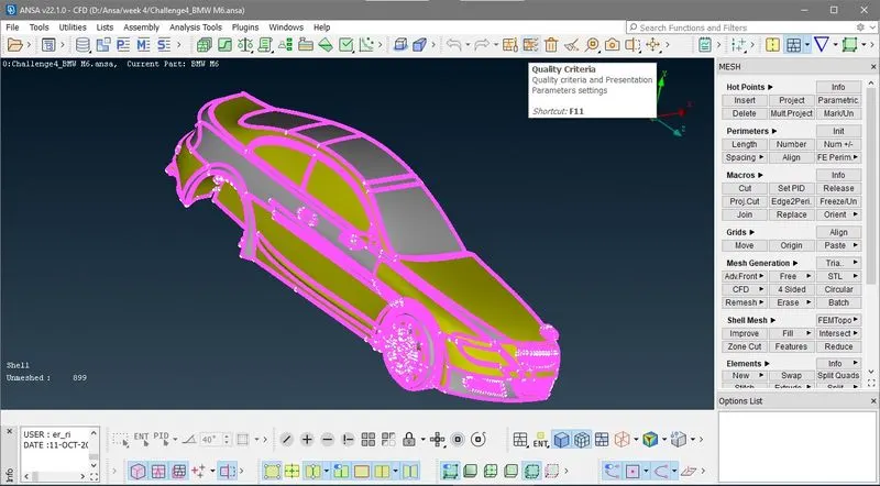
3) Unhide qulity check criteria
4) 2D Surface meshing
Now come to PID selection mode isolate grills and logo PID'S ang go to meshing slect CFD Mesh, Tri element and give minmum and maximum target length 0.5 and 2 respectvly.
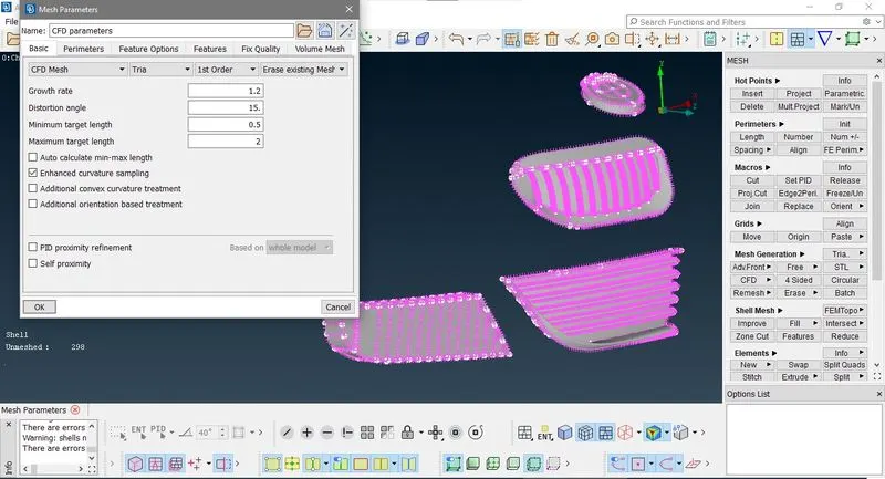
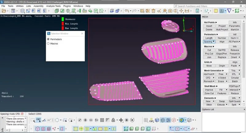
Now got to Mesh>Spacing>Perimeter Select perimeter and box select the visible geometry as shown in image
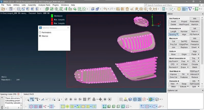
then select macro and again select gemometry.
Now go to Mesh>Mesh Generation >CFD>Visible
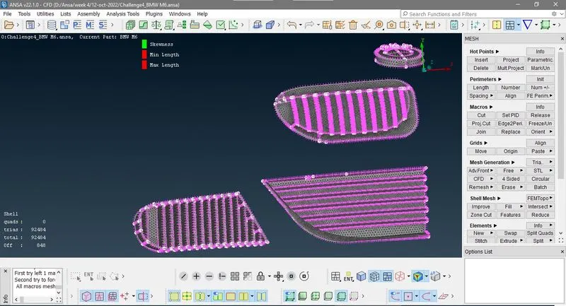
You can see in above image tri elements are 92494 and off element are 849 ,Now right click this click improve in drop down list then select Reconstruct click next 3 times
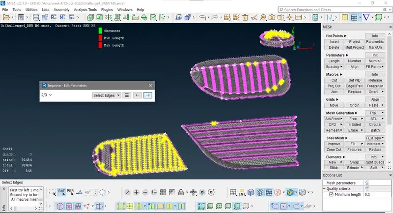
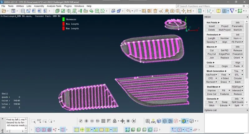
Now you can see number of tria element increas to 94046 and off element ony 2 Now rigth clik again and click show
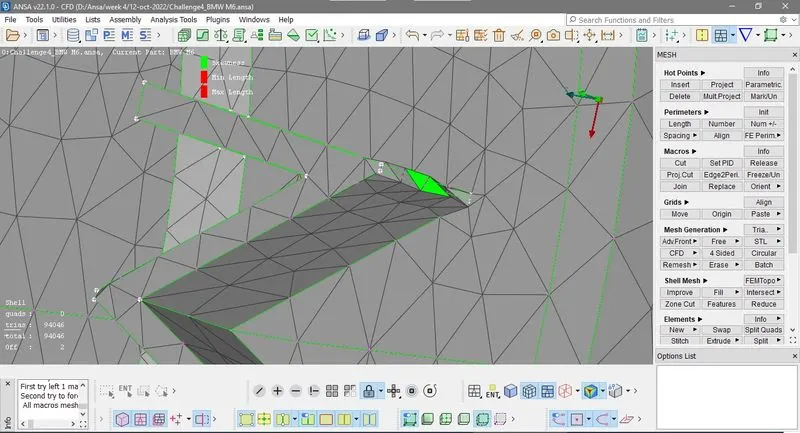
Now you can see on above image off element are at sharp edge of "M" in logo , now you understand why we try to remove sharp edges in geometry. here at this point we solve it manualy so go to Mesh> Grids> Move
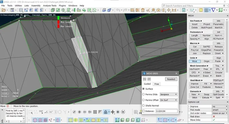
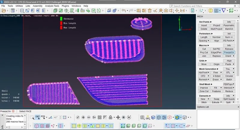
Now there is no off element in this mesh geometry. Before going to meshing of next PID'S first we frozen those perimeter which are alos present in another PID at boundaries.
Now meshing for those PID taget length 2mm hide all PIDS only Rims and tyres ,mirror and window PID is shown
then meshing with minmum and maximum target length 1 and 3 respectvely.
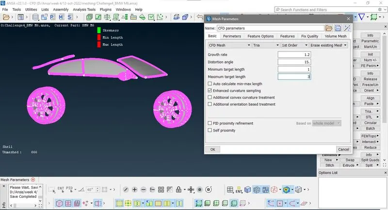
Now go to Mesh>Spacing>Auto > perimeter Select perimeter and box select the visible geometry as shown in image
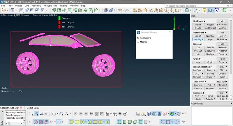
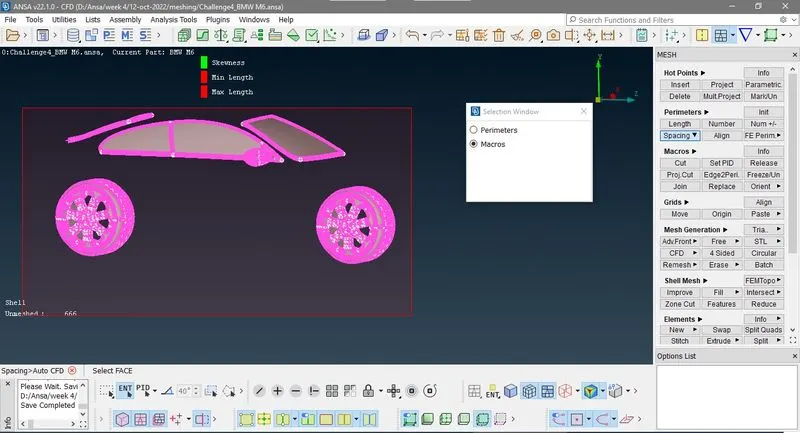
Now go to Mesh>Mesh Generation >CFD>Visible

You can see in above image tri elements are 199234 and off element are 203 ,Now right click this click improve in drop down list then select Reconstruct click next 3 times
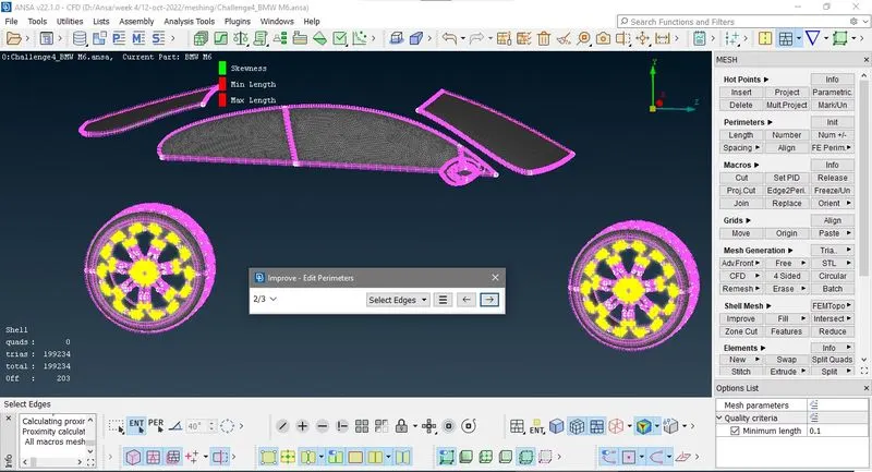
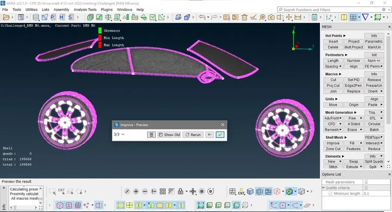
Now there is no off element in this mesh geometry. Before going to meshing of next PID'S first we frozen those perimeter which are alos present in another PID at boundaries.
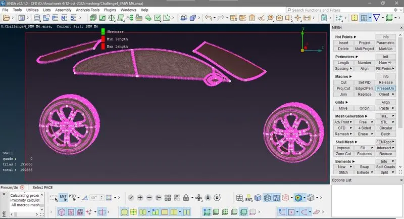
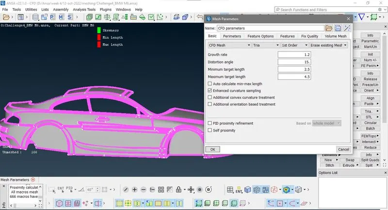
Now again come to PID selection mode isolate body and silencer PID'S ang go to meshing slect CFD Mesh, Tri element and give minmum and maximum target length 2.5 and 4.5 respectvly.
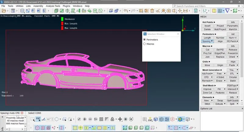
Now again go to Mesh>Spacing>Auto > perimeter Select perimeter and box select the visible geometry as shown in image
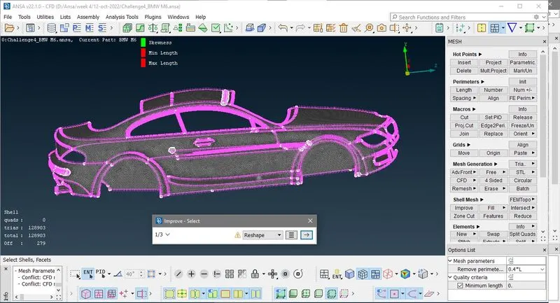
You can see in above image tri elements are 128903 and off element are 279 ,Now right click this click improve in drop down list then select Reconstruct click next 3 times
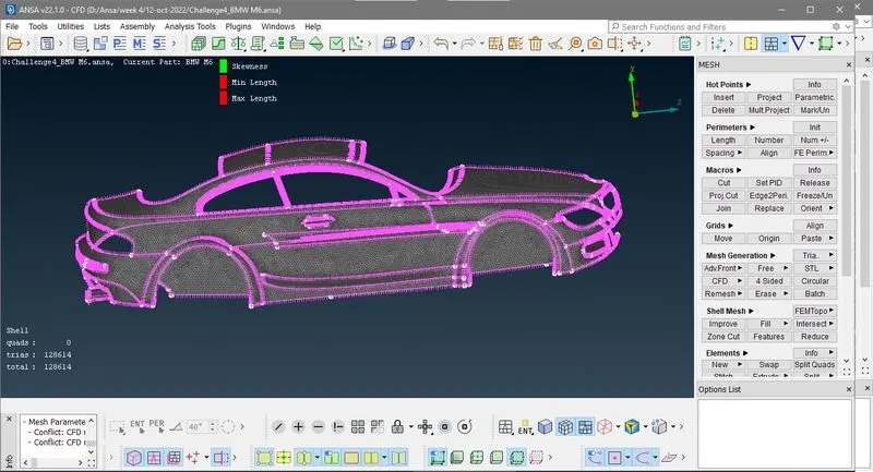
then mesh head light PID with minmum and miximum target length 3.5 to 5.5 and after mesh generating you ge 1356 tria elements. Then show all PID.'s
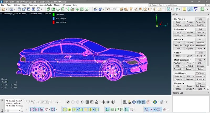
5) Creating and meshing wind tunnl
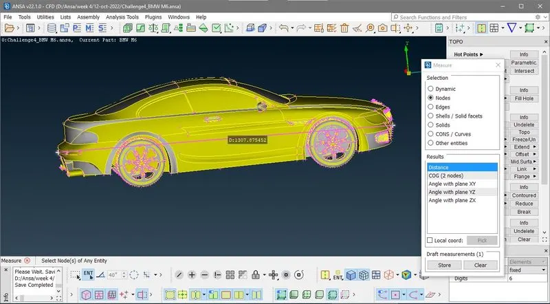
First we have to measure length of model (i.e. car), here you can see in above image it is 1307.87 , i take overall valve of length 1310 inside which my all geometry comes.
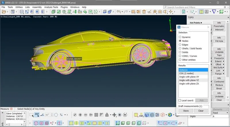
Now be measur end point to someware in mid poin
now if we see bellow image our boundar should be like this
front face is 4x time of model length
back face 6x times of model length
side wall at distance equal to model length
top face is at 3x time of model length
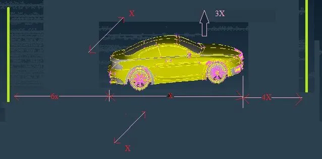
Now create a point at by useing relative first click center bottom point as shoen in image
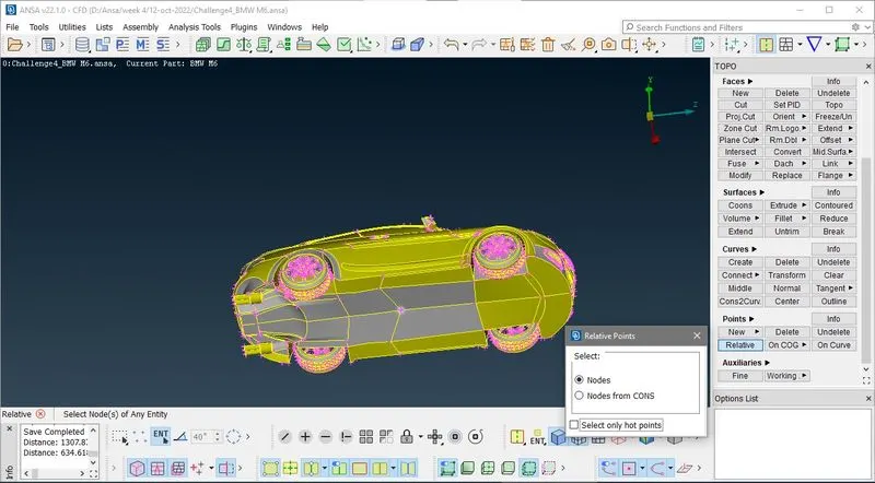
Now press mouse middle button and give dy value -500 ( because we want to make a close volume out side which no model geometry is going.
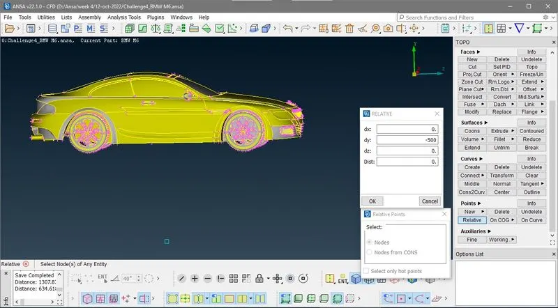
Now again make a point at distance 8510= (1310*6)+650
note take -ve value because we have to og in -ve z direction
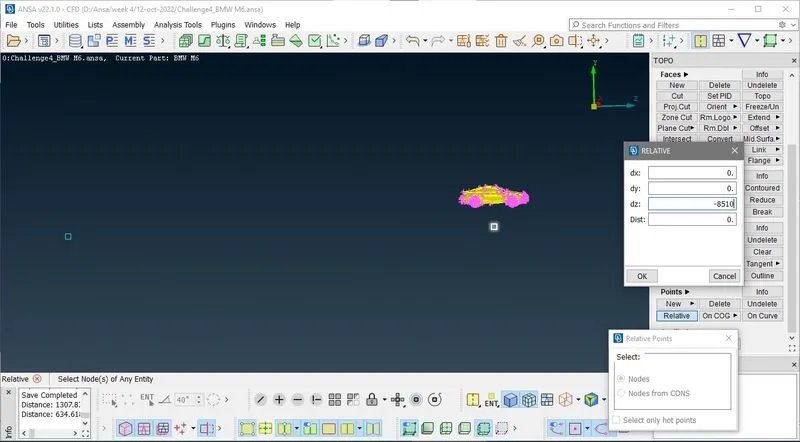
Now again make a point at distance 5900= (1310*9)+660
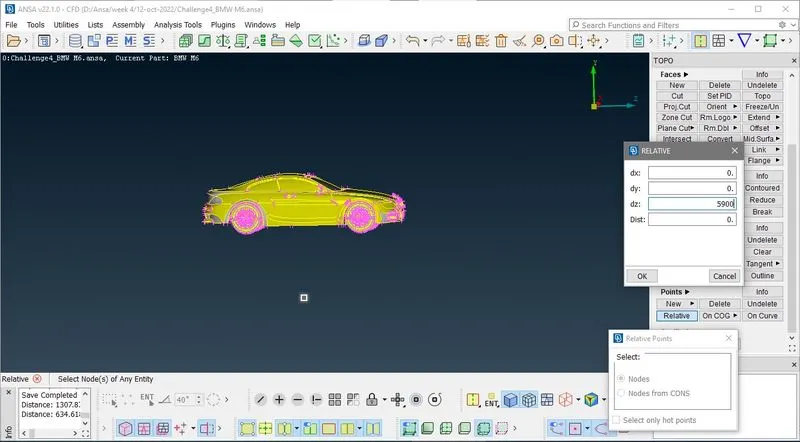
Siminlarly i make point in x direction also
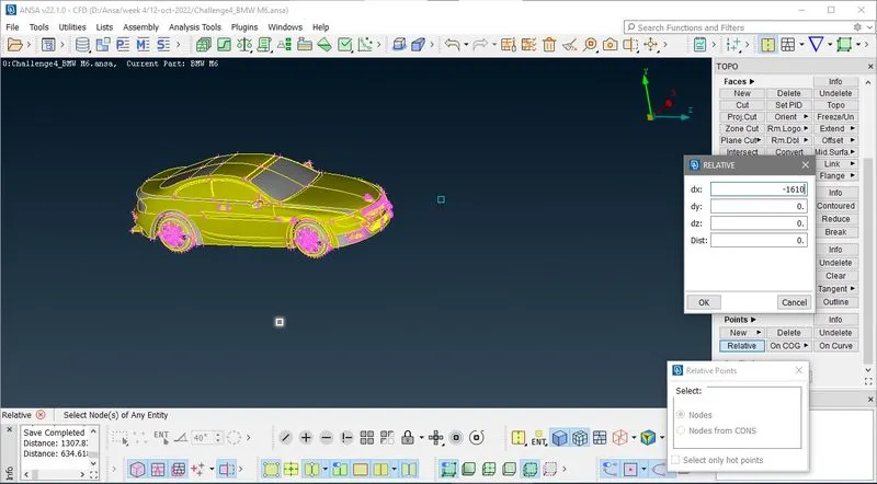
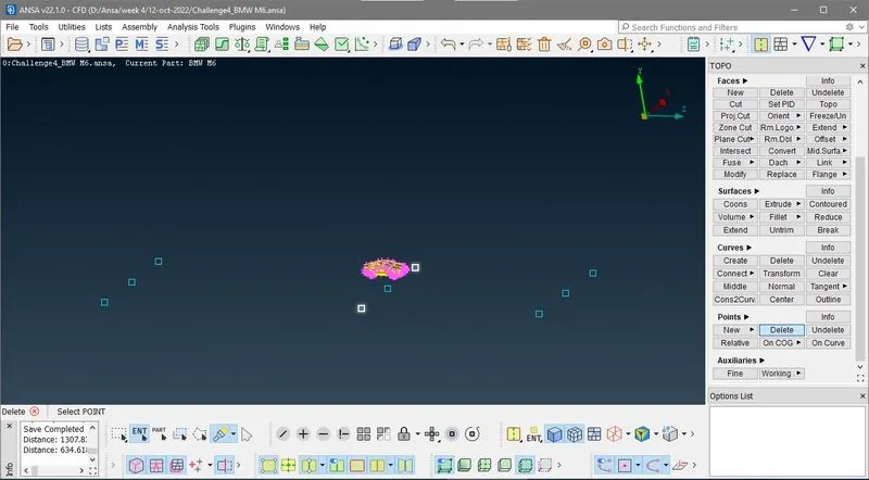
Now create curve (line for straight line)
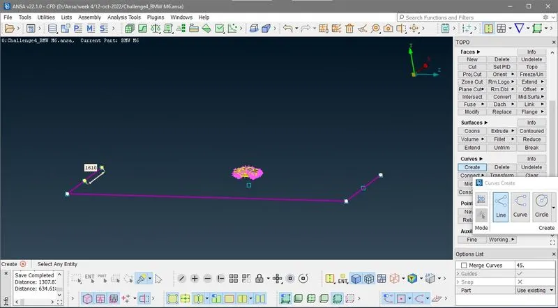
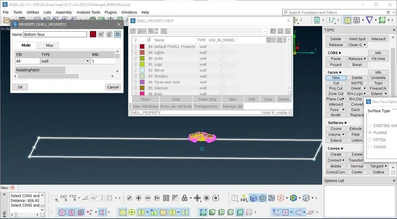
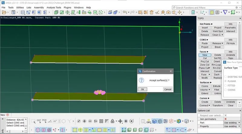
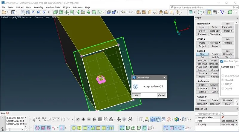
Now create a new planer face with these currves
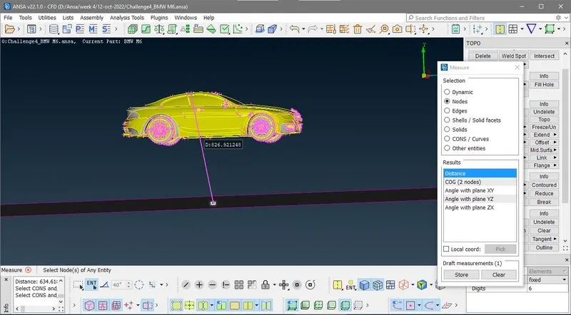
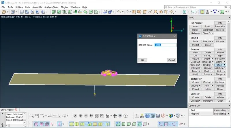
After that mesure point on top of car and bottom face
it is 830+3*1310=4760 aproximatey i conside 5000 because my selection in measure in good
First i delet curves and points
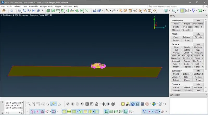
here my direction is opposite to arrow shown in below image so i give -ve value
Now are going to mesh wind tunnel
first mesh Bottom face with target length 20mm
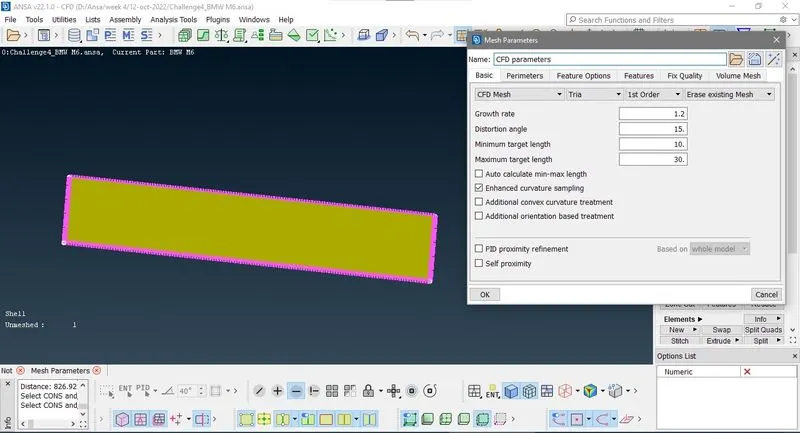
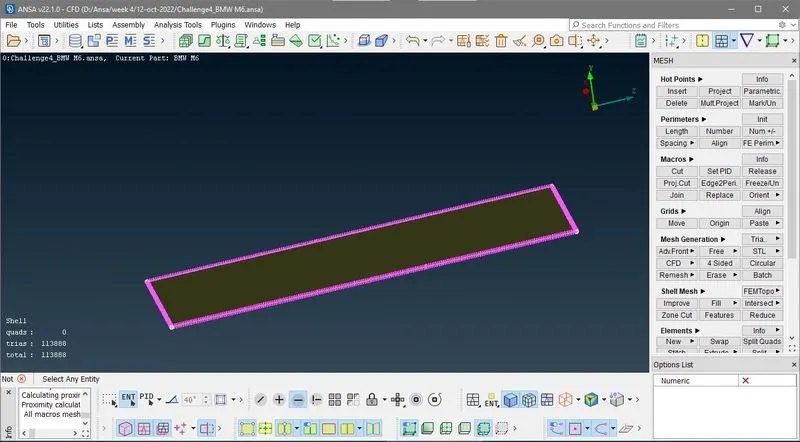
Now we mesh top face with target length 100mm
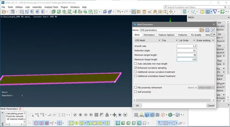
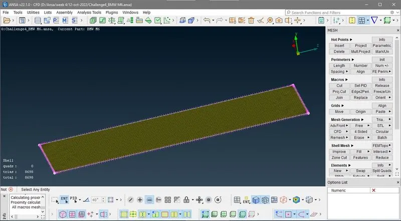
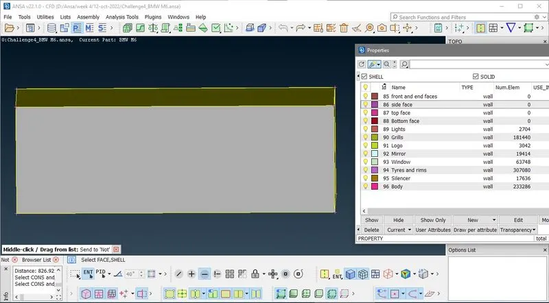
Now go to property tool bar and show only those PID of wind tunel
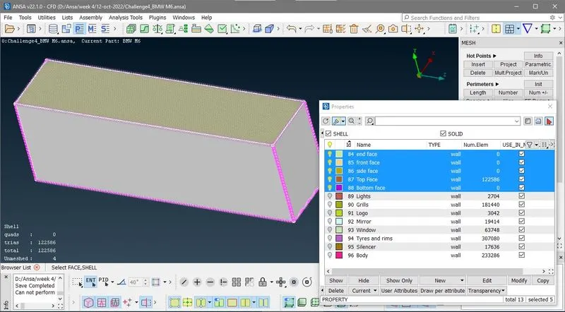
then going to spacing > manual
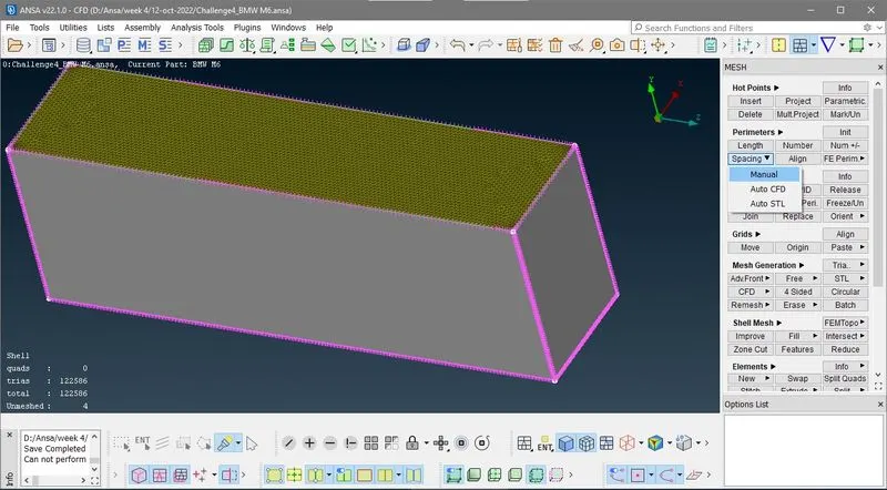
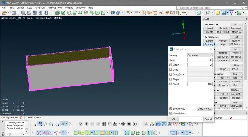
Now we give manual direction of groth of mesh size from 2o mm to 1oo mm as shown in below image
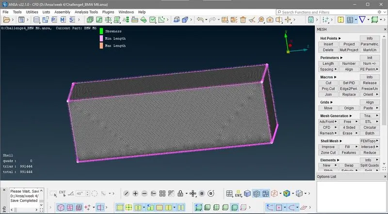
After CFD MESHING
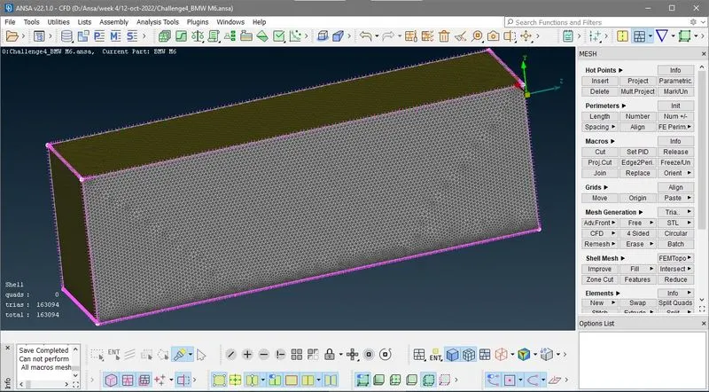
Show all then
Conclusion:-
- In this challange we learn various topological optimizer tool like planer cut, project cut,paste, undeleted , cons2corv and extend ect.
- In challange how sharp edges ingeometry produce skewness error.
- In this challange we also lear about quality check like skewness, max and min length ect.
- In this challange how to improve and reconstruct off element Automaticaly and manualy.
- In this challange we learn how to creates wind tunnel and how to mesh it.
Dwonload model at this google link
https://drive.google.com/file/d/1RhcfrW3qfucDml32dbFIVibrPZN3JYqz/view?usp=sharing