Week 4 Challenge : CFD Meshing for BMW car
Aim
Perform meshing with the given Target length and element Quality criteria. After meshing the half model, Do symmetry to the other side.
- Target lengths for the different parts of a model are as follow:
- Body - 3 mm
- Lights - 4 mm
- Grills - 1 mm
- Rims and Tyres - 2 mm
- Optical Rear view mirror - 2 mm
- Window - 2 mm
- Silencer - 3 mm
- Logo - 1 mm
Procedure
- After importing model delete half model and ‘topo’ is applied on it to join the single cons into double and triple con.
- Con resolution can be improved by giving whole model a perimeter and macros length as 1mm in mesh deck that will smooth he con.
- Single cons and triple cons are identified and Topo-cleanup is done to patch the open surface and delete unwanted surface.
- Topo cleanup for grills is done by deleting unnecessary surfaces from grills to remove triple cons, delete un-wanted hot points, and single cons are removed by patching the surfaces using New-Coons/Fitted options
- Topo cleanup tyre’s and side mirror and head and tail light, includes removing triple cons by deleting the unwanted surfaces.
- For a logo the overlapped surfaces were identified and separated by projecting those surfaces on hood and are deleted followed by removing small edges which may cause error during meshing.
- Lower car body need to corrected by removing unwanted protruding parts and the part of lower body intersecting with tyres need to be deleted to make tyres as a free volume. For keeping track of different parts in lower body ‘cons2curve’ is used to have blueprint of deleted surfaces with help of which new surfaces are created.
- Geometric checks are performed to have no single cons present in the model and possible triple cons are removed by deleting it using universal delete option.
- PID’s are assigned using the PID manager for all parts in the body.
- Before creating surface mesh the cons and small edges that have length less than minimum mesh length are identified by measuring the distance between cons and solved using ‘cut’ option in order to avoid mesh failing the mesh criteria at this small surfaces. The final Topocleanup model is shown in fig.1.
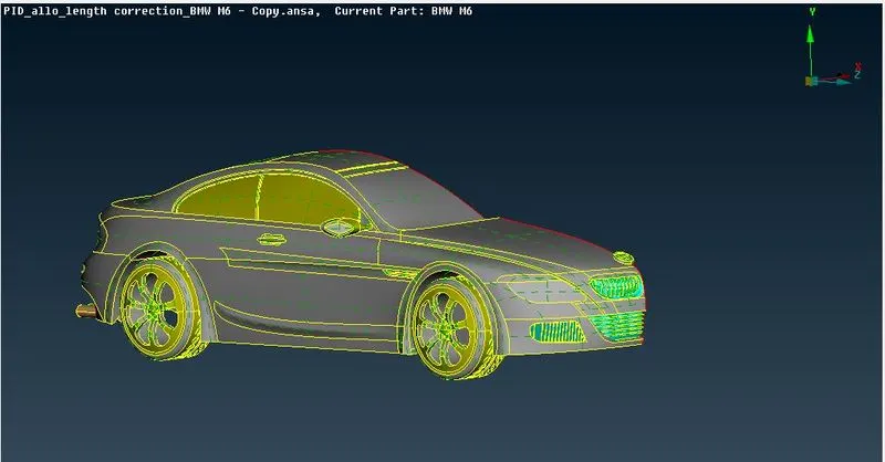
Figure 1
Surface Mesh
Target lengths for the different parts of a model are as follow:
- Body - 3 mm (min: 1mm , max: 5mm)
- Lights - 4 mm (min: 3mm , max: 5mm)
- Grills - 1 mm (min: 0.4mm , max: 2mm)
- Rims and Tyres - 2 mm (min: 1mm , max: 3mm)
- Optical Rear view mirror - 2 mm (min: 1mm , max: 3mm)
- Window - 2 mm (min: 1mm , max: 3mm)
- Silencer - 3 mm (min: 1mm , max: 4mm)
- Logo - 1 mm (min: 0.5mm , max: 2mm)
- Individual elements are meshed with respective mesh length with minimum and maximum length.
- Surface meshing for Grills: Grills are isolated and given a mesh length of 1mm with minimum and maximum length of 0.5mm and 2mm with triangular elements. Other mesh criteria’s are as shown in figure 2.
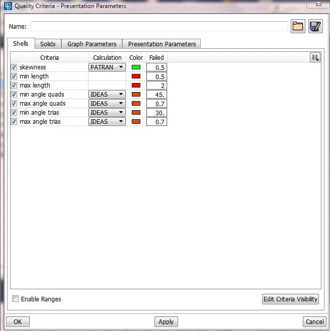
Figure 2
- The mesh is seen in Hidden Mode and ENT wise, which will show off elements which are violating the criteria as shown in figure
- The mesh improvement can be done by using options like Reconstruct, Split, Smooth, Move the grid.
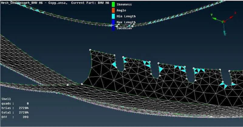
Figure 3
- Once the off element’s number boils down to 0 then meshing is done successfully, and Similar method is used for other PID’s. The Final Mesh on the half part of car is shown in the figure.
- Symmetry need to be performed on the other half of car in which the all the components with mesh are copied directly to the other side using Transform option from the top side option list. The full mesh model of a car is as shown in fig 4.
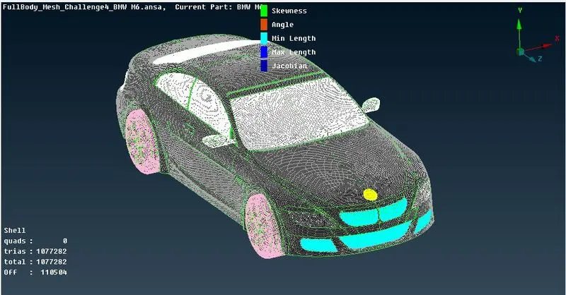
Figure 4
Wind Tunnel
- The wind tunnel dimensions are , if x is the length of car then
Front of wind tunnel is 4X from the car
Rear of wind tunnel is 6X from the car
Top of wind tunnel is 3X from the car
Side walls of wind tunnel are at X from the side portion of car
Bottom of wind tunnel is in close proximity of wheels
- Points are created by using ‘Relative option’ in points of Topo Deck.
- Topo Deck- points- relative –points- select points. After the points are created join these points from bottom plane by ‘create curves’
- Once the curves are created for top and bottom then create a surface with help of ‘New’ option in ‘faces’
- Topo – Faces- New-Fitted-will open PID manager window- create new PID-double click on it to create surface on it.
- As the analysis of what happens over the surfaces of car is of importance so the bottom of wind tunnel should have good resolution as compared to top portion as it relatively at larger distance than bottom. So mesh length of 20 is taken at bottom and 100 for top portion.
- As the front and rear of car are connected with the top and bottom surfaces then the mesh length for this surfaces should vary from 20 to 100 from bottom to top portion. This gradual variation can be achieved using Spacing option from the perimeters section of Mesh deck.
Perimeters-Spacing –Geometric – factor of 1.1 and d-min of 20 successful application of this will be indicated by upward pointing arrows.
- Mesh is generated by applying Spot mesh for individual surfaces. The final surface mesh for wind tunnel is shown in fig 5.
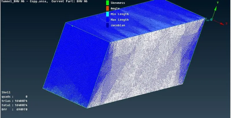
Figure 5
Conclusion
1. All parts were surface meshed including wind tunnel surface.
2. Here the off elements are occurred at the intersection of Body with other PID’s where two different mesh lengths are coming in contact with each other. Here in this portion mesh length will try to adjust so it will be transition in the form of off elements at the location where PID’s meet each other. These errors are of minimum length error so this error is not considered as an error but an obvious behavior of mesh lengths in transition.
In order to avoid this, we should keep the body with minimum length less than the minimum length of Grills and Logo because the intersection at this PID’s with Body are causing off elements in the case when body is meshed at the end.
3. For meshing Body PID, without risk of erasing the mesh on PID’s which are in direct contact with body:
All (bring whole car)- Hide body PID- Macros-Freeze-box select rest parts- middle click- Hide rests-now mesh body – after that hide body- unfreeze the frozen parts by box selecting (shift + right click) parts – middle click – Now all – and there will be no erasing of mesh at intersection.
Link
Wind Tunnel : https://drive.google.com/file/d/1Xh-q5YarpcbF3Q0KDyAqh2je1gUBLAf2/view?usp=sharing
Full Meshed Car : https://drive.google.com/file/d/1Y3zeXlaAbvPKpx0FrgW8uzIUG_TC-Sc3/view?usp=sharing